EP0254776A2 - Filtre pour lubrifiants de moteurs à combustion interne contenant une réserve d'additifs - Google Patents
Filtre pour lubrifiants de moteurs à combustion interne contenant une réserve d'additifs Download PDFInfo
- Publication number
- EP0254776A2 EP0254776A2 EP86201950A EP86201950A EP0254776A2 EP 0254776 A2 EP0254776 A2 EP 0254776A2 EP 86201950 A EP86201950 A EP 86201950A EP 86201950 A EP86201950 A EP 86201950A EP 0254776 A2 EP0254776 A2 EP 0254776A2
- Authority
- EP
- European Patent Office
- Prior art keywords
- filter
- bowl
- lubricant
- additives
- reservoir
- Prior art date
- Legal status (The legal status is an assumption and is not a legal conclusion. Google has not performed a legal analysis and makes no representation as to the accuracy of the status listed.)
- Granted
Links
Images


Classifications
-
- B—PERFORMING OPERATIONS; TRANSPORTING
- B01—PHYSICAL OR CHEMICAL PROCESSES OR APPARATUS IN GENERAL
- B01D—SEPARATION
- B01D37/00—Processes of filtration
- B01D37/02—Precoating the filter medium; Addition of filter aids to the liquid being filtered
- B01D37/025—Precoating the filter medium; Addition of filter aids to the liquid being filtered additives incorporated in the filter
-
- B—PERFORMING OPERATIONS; TRANSPORTING
- B01—PHYSICAL OR CHEMICAL PROCESSES OR APPARATUS IN GENERAL
- B01D—SEPARATION
- B01D27/00—Cartridge filters of the throw-away type
- B01D27/08—Construction of the casing
-
- B—PERFORMING OPERATIONS; TRANSPORTING
- B01—PHYSICAL OR CHEMICAL PROCESSES OR APPARATUS IN GENERAL
- B01D—SEPARATION
- B01D27/00—Cartridge filters of the throw-away type
- B01D27/10—Safety devices, e.g. by-passes
- B01D27/103—Bypass or safety valves
-
- B—PERFORMING OPERATIONS; TRANSPORTING
- B01—PHYSICAL OR CHEMICAL PROCESSES OR APPARATUS IN GENERAL
- B01D—SEPARATION
- B01D27/00—Cartridge filters of the throw-away type
- B01D27/10—Safety devices, e.g. by-passes
- B01D27/106—Anti-leakage or anti-return valves
-
- B—PERFORMING OPERATIONS; TRANSPORTING
- B01—PHYSICAL OR CHEMICAL PROCESSES OR APPARATUS IN GENERAL
- B01D—SEPARATION
- B01D27/00—Cartridge filters of the throw-away type
- B01D27/14—Cartridge filters of the throw-away type having more than one filtering element
- B01D27/142—Cartridge filters of the throw-away type having more than one filtering element connected in parallel
- B01D27/144—Cartridge filters of the throw-away type having more than one filtering element connected in parallel arranged concentrically or coaxially
-
- F—MECHANICAL ENGINEERING; LIGHTING; HEATING; WEAPONS; BLASTING
- F01—MACHINES OR ENGINES IN GENERAL; ENGINE PLANTS IN GENERAL; STEAM ENGINES
- F01M—LUBRICATING OF MACHINES OR ENGINES IN GENERAL; LUBRICATING INTERNAL COMBUSTION ENGINES; CRANKCASE VENTILATING
- F01M1/00—Pressure lubrication
- F01M1/10—Lubricating systems characterised by the provision therein of lubricant venting or purifying means, e.g. of filters
- F01M2001/105—Lubricating systems characterised by the provision therein of lubricant venting or purifying means, e.g. of filters characterised by the layout of the purification arrangements
- F01M2001/1071—Lubricating systems characterised by the provision therein of lubricant venting or purifying means, e.g. of filters characterised by the layout of the purification arrangements comprising oil tanks
-
- F—MECHANICAL ENGINEERING; LIGHTING; HEATING; WEAPONS; BLASTING
- F01—MACHINES OR ENGINES IN GENERAL; ENGINE PLANTS IN GENERAL; STEAM ENGINES
- F01M—LUBRICATING OF MACHINES OR ENGINES IN GENERAL; LUBRICATING INTERNAL COMBUSTION ENGINES; CRANKCASE VENTILATING
- F01M1/00—Pressure lubrication
- F01M1/10—Lubricating systems characterised by the provision therein of lubricant venting or purifying means, e.g. of filters
- F01M2001/105—Lubricating systems characterised by the provision therein of lubricant venting or purifying means, e.g. of filters characterised by the layout of the purification arrangements
- F01M2001/1092—Lubricating systems characterised by the provision therein of lubricant venting or purifying means, e.g. of filters characterised by the layout of the purification arrangements comprising valves bypassing the filter
-
- F—MECHANICAL ENGINEERING; LIGHTING; HEATING; WEAPONS; BLASTING
- F01—MACHINES OR ENGINES IN GENERAL; ENGINE PLANTS IN GENERAL; STEAM ENGINES
- F01M—LUBRICATING OF MACHINES OR ENGINES IN GENERAL; LUBRICATING INTERNAL COMBUSTION ENGINES; CRANKCASE VENTILATING
- F01M9/00—Lubrication means having pertinent characteristics not provided for in, or of interest apart from, groups F01M1/00 - F01M7/00
- F01M9/02—Lubrication means having pertinent characteristics not provided for in, or of interest apart from, groups F01M1/00 - F01M7/00 having means for introducing additives to lubricant
Definitions
- the present invention relates to a filter for lubricants of internal combustion engines, particularly for motor vehicles, provided with a reserve of additives.
- the invention relates to a filter of the screwed-on type, in which the additives of the reserve can be introduced into the flow of the lubricant when desired.
- filters for lubricants of internal combustion engines which contain mixtures of additives designed to integrate or replace the additives which are originally present in the lubricant and which after a certain period of operation are normally consumed or degraded.
- a filter designed by the Applicant himself and described in U.S.A. Patent No. 4,265,748 on the other hand, is based on a different principle of introduction of additives, namely on the complete and sudden introduction of the additives into the flow of the lubricant only after a certain period of operation when the original additives are supposed to be completely consumed or degraded. This is obtained by placing the additives in a container inside the filter, provided with at least one wall that is slowly soluble in the lubricant so as to produce - when the wall has been completely dissolved - the complete and immediate introduction of the additives into the lubricant. The moment of introduction is determined in advance as a function of the life of the lubricant on the basis of the chemical nature and the physical structure of the soluble wall of the container.
- the filters of the type with slow introduction of the additives are not considered satisfactory for optimum duration and quality of modern lubricants as these lubricants - when they are brought into commerce - already contain additives in such an amount as to ensure a good performance over a long period of time so that it is neither nor correct to increase the level of introduction of additives from the very beginning even if only in a gradual manner.
- the filter of the U.S.A. Patent No. 4,265,748 mentioned above although it is based on a more correct principle of introduction of additives, does not permit to determine exactly the moment of introduction of the additives into the flow of lubricant as this moment, in addition to the characteristics of the soluble wall of the container, also depends on the operating conditions, on the state of the engine and on other factors which cannot be exactly ascertained or determined in advance.
- a filter for lubricants of internal combustion engines comprising a bowl containing at least one filter cartridge, a cover with a plurality of eccentric inlet apertures for the lubricant to be filtered and two outlet apertures for the filtered lubricant, an axial one and another intermediate one, a sleeve which extends axially from said cover in the direction towards the bottom of the bowl, sealing means between the outer surface of said sleeve and said filter cartridge for separating the flow of filtered lubricant and feeding it to said outlet apertures, characterized in that incorporated in said bowl is a reservoir for lubricant additives, communicating with the rest of the filter by means of a feed hole normally closed by a check valve, and by means of a conduit normally closed by an on-off valve actuatable, if desired, to mix the additives contained in said reservoir with the lubricant flowing in the filter.
- the filter according to the invention is of the bypass type with double filtering and comprises a bowl 1 of deep-drawn sheet metal with a conical bottom and closed upwardly by a cover 2 - made substantially as described in the U.S.A. Patent No. 4,265,748 of the same Applicant - and two axially superimposed filter cartridges 3, 4, the first one adapted to effect rough filtering on the major portion of the flow of lubricant and the second one adapted to effect a fine, i.e. more intense filtering on only a portion of the flow of lubricant.
- the entry of the lubricant into the filter takes place in the direction of the arrows A through a series of eccentric holes 5 from which the lubricant is admitted to the outer zone 9 of the filter cartridges to then traverse them radially towards the interior.
- An axial sleeve 10 firmly secured to the cover extend from the latter up to the height of the rough filter cartridge 3.
- the upper and lower bases of both the filter cartridges are closed so that the lubricant can traverse the filter elements only in the radial direction.
- An annular gasket 12 is accommodated between the sleeve 10, the lower base of the upper cartridge 4 and the upper base of the lower cartridge 3 to separate the flow of the lubricant filtered in the two cartridges.
- the lubricant subjected to rough filtering is conducted into the interior of the sleeve 10 and then to the axial outlet hole 6 whereas the lubricant subjected to fine filtering rises in the gap 15 - defined between the sleeve 10, the cartridge 4, the gasket 12 and an upper gasket 13 placed between the lower base of the cartridge 4 and a shoulder 8 of the sleeve 10 - and leaves the filter through the intermediate outlet hole 7.
- the axial hole 6, which is threaded to permit the filter to be mounted by screwing on (filter of the spin-on type), is in communication with the engine whereas the intermediate hole 7 leads to the oil sump, not shown.
- Accommodated in appropriate seats above the cover 1 are two circular gaskets 16, 17 for sealing to the engine block and for separating the lubricant leaving the filter from the lubricant entering it.
- a circular wall 20 which separates the lower portion of the bowl 1 from the upper portion where the filtering takes place, so as to form a reservoir 8 for a reserve of additives to the lubricant.
- the wall 20 is mounted by means of a rubber ring 11 inserted in a central hole thereof, on an axial conduit 21 formed integrally with the sleeve 10 into which it penetrates to a certain length and to which it is connected by an elbow 22 opening into the gap 15.
- a circular gasket 23 seals the outer edge of the wall 20 against the inner surface of the bowl, but nevertheless permits the wall to make small axial movements due to the oil pressure existing thereabove.
- a hole 24 is provided in the wall 20, this hole being normally closed by a one-way check valve 25 which can be opened by a difference in pressure, as will be explained hereinafter.
- a spiral spring 28 adapted to keep in position both the filter cartridges in the interior of the bowl.
- the spring is upwardly received in a recess 14 of the filter cartridge 3 in the centre of which there is provided a hole in which a second rubber ring 11 ⁇ is arranged for sealing against the conduit 21.
- an aperture 29 which is closed by a relief valve 30, as is known in the art, to ensure the flow of the lubricant even in case of clogging of the filter.
- the lower end of the conduit 21 is normally closed by an on-off piston valve 32 comprising a body 33 of larger diameter, which extends up to the bottom of the bowl where it is received in a seat 34 the lower portion 34 ⁇ of which is threaded and engages to cylindrical lower portion 33 ⁇ of the body 33 which is likewise threaded.
- the lower portion 33 ⁇ of the body 33 is formed integrally with a knob 35 located outside the bowl and adapted to translate axially to unscrew the entire body 33. In this manner the small piston 32 can be removed from the conduit 21 and thus the reverse of additives can be brought into communication with the portion of the filter where filtering takes place, and vice versa.
- Appropriate gaskets 36, 36 ⁇ ensure sealing of the small piston 32 in the conduit 21 and of the body 33 in the seat 34, respectively.
- a ring 37 abutting the seat 34 limits the path of the body 33 during unscrewing and prevents the small piston 32 from being drawn out of the conduit 21.
- a perforated cup 38 is fitted, by means of an axial hole made in the bottom 38 ⁇ , on the piston 32 and engages the abutment 39 defined between the piston 32 and the body 33 of larger diameter. This cup serves to limit the axial movement of the wall 20 produced by the pressure of the lubricating circuit acting above the wall.
- the pressure of the lubricant even if it is small, opens the valve 25, so that the lubricant, which normally is confined above the wall 20, can pass through the hole 24 and invade the reservoir of the additives, mixing therewith, to then flow out through the conduit 21 and the elbow 22 up to the gap 15.
- the lubricant having a high concentration of fresh additives mixes with the lubricant subjected to fine filtering and leaves the filter through the intermediate hole 7 leading to the oil sump where the additives mix with a larger quantity of lubricant until they rapidly reach the optimum concentration.
- the operation of reintegration only takes a few seconds and after that the user screws up the knob 35 again.
- the lubricant contained therein is excluded from the lubricating circuit the volume of which will, however, remain unchanged by the addition of the additives. It is, however, to be taken into consideration that the volume of the reservoir is negligible in comparison with the overall volume of the lubricating circuit.
- Fig. 2 shows in a part sectional view a modification of the embodiment. of Fig. 1.
- the wall 20 is secured to the bowl 1 by means of a deep-drawn double step 40 made therein.
- a deep-drawn double step 40 made therein.
- any gasket on the edge of the wall which is bent upwardly in the manner of a rib 41 forced against the deep-drawn step.
- the presence of the stop cup 38 on the small piston 32 is no longer required.
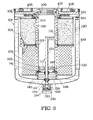
- this filter has a structure and operation identical to the embodiment described in Fig. 1; therefore, the various parts have been given numbers corresponding to those of Fig. 1 with the addition of 100.
- the filter of Fig. 3 likewise comprises substantially a bowl 101 closed upwardly by a cover 102 and containing a rough filter cartridge 103 and a fine filter cartridge 104, the two cartridges being superimposed.
- cover there are provided inlet holes 105 for the lubricant to be filtered, an outlet hole 106 for the lubricant filtered by the cartridge 103, and an intermediate hole 107 for the lubricant filtered by the cartridge 104.
- An axial sleeve 110 secured upwardly between the cover and an annular gasket 113 feeds the lubricant coming from the cartridge 103 to the hole 106 and separates it by means of an annular gasket 112 inserted between the sleeve and the two cartridges 103, 104 from the lubricant coming from the cartridge 104, which is fed to the intermediate hole 107 and further to the oil sump.
- the bowl 120 there is a second bowl 120 between the bowl 101 and the filter cartridges, with the walls of this second bowl extending parallel to those of the bowl 101 and connected and secured thereto adjacent the cover 102.
- the bowl 120 extends coaxially to the bowl 101, but is separated therefrom so that between the two a reservoir 108 is formed for stocking the reverse of additives.
- a lower spring 128 keeps the filter cartridges in position and a rilief valve generally indicated by 130 ensures passage of the lubricant even in case of clogging of the filter cartridges.
- the valve indicated by 130 is substantially constituted by a rubber ring 140 which normally closes holes 129 provided in the bottom of the cartridge 103.
- the ring 140 is kept in position by a disk 141 biassed by a helical spring 142 reacting against an appropriate seat 143 provided on the base of the sleeve 110.
- An outflow conduit 121 brings the reservoir 108 into communication with the gap 115 defined between the sleeve 110 and the fine filter cartridge 104.
- a piston valve 132 closes the lower end of the conduit 121 and is received in a seat 134 and engages with its lower threaded portion 133 the corresponding threaded portion 134 ⁇ of the seat 134.
- An outer knob 135 formed integrally with the body of the piston permits the end of the conduit 121 to be opened by unscrewing, and vice versa.
- Two elastic sealing rings 111 and 111 ⁇ are fitted on the conduit 121 and more precisely on an axial hole provided in the bottom of the inner bowl 120 and in the bottom of the lower cartridge 102, respectively.
- a hole 124 is provided which is closed by a one-way check valve 125 having the purpose of permitting the lubricant to enter the reservoir 108 when the conduit 121 is opened by the on-off piston valve 132.
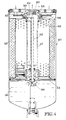
- Fig. 4 illustrates a different embodiment of the filter according to the invention, in the case of continuous total (full-flow) filtering.
- the structure of the filter is substantially analogous to that of the filter of Fig. 1 and comprises a bowl 50 with a cover 52 completely identical to the cover 2 of Fig. 1, so that we may refrain from describing it.
- Accommodated in the bowl is a single filter cartridge 53 through which the lubricant entering the filter is continuously filtered.
- a wall 55 which in the portion below defines a reservoir 58 for a reserve of additives, as in the case of the filter of Fig. 1.
- Arranged in the interior of the cartridge 53 is an axial sleeve 57 secured upwardly to the cover of the bowl and provided with a shoulder 58 ⁇ adapted to retain an annular sealing gasket 56 against the upper base of the cartridge 53.
- the sleeve 57 is formed integrally with a conduit 59 located therein and provided with an elbow 60 opening adjacent the upper portion of the cartridge 53 above an annular gasket 62 which prevents the filtered lubricant from entering the annular chamber 64 communicating with the intermediate outlet hole 65 leading to the oil sump.
- the conduit 59 sealingly passes through the wall 55 and is closed by an on-off piston valve 66 completely identical to that of Fig. 1, so that we may refrain from describing it or its actuation or operation.
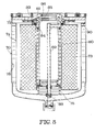
- Fig. 5 illustrates a further embodiment of the filter according to the invention, again relating to a filter with continuous total (full-flow) filtering.
- This embodiment is analogous to the one of the filter of Fig. 3 and substantially comprises an outer bowl 70 closed by a cover 72, as described previously, and a second bowl 74 located inwardly of and coaxially to the first one and defining a gap 78 serving as a reservoir for the additives.
- a single filter cartridge 73 kept in position by a helical spring 75 reacting against the bottom of the inner bowl 74.
- an axial sleeve 80 which upwardly is firmly secured to the cover of the bowl and is provided with a shoulder 81 adapted to retain an annular gasket 83 against the upper base of the bowl 74.
- a second annular gasket 84 is arranged between the sleeve and the inner wall of the cartridge 73 in the vicinity of the cover so as to define an annular chamber 85 closed to the flow of the filtered lubricant which leaves the filter by passing through the interior of the sleeve 80 and through the central hole 86.
- an axial conduit 89 brings the chamber 85 into communication with the reservoir 78 of the additives.
Landscapes
- Chemical & Material Sciences (AREA)
- Chemical Kinetics & Catalysis (AREA)
- Lubricants (AREA)
- Lubrication Details And Ventilation Of Internal Combustion Engines (AREA)
- Filtering Materials (AREA)
- Filtration Of Liquid (AREA)
- Lubrication Of Internal Combustion Engines (AREA)
Priority Applications (1)
| Application Number | Priority Date | Filing Date | Title |
|---|---|---|---|
| AT86201950T ATE61247T1 (de) | 1986-06-27 | 1986-11-10 | Filter fuer schmiermittel mit additivreserve fuer brennkraftmaschinen mit innerer verbrennung. |
Applications Claiming Priority (2)
| Application Number | Priority Date | Filing Date | Title |
|---|---|---|---|
| IT6751586 | 1986-06-27 | ||
| IT67515/86A IT1192015B (it) | 1986-06-27 | 1986-06-27 | Filtro per lubrificanti di motori a combustione interna con riserva di additivi |
Publications (3)
| Publication Number | Publication Date |
|---|---|
| EP0254776A2 true EP0254776A2 (fr) | 1988-02-03 |
| EP0254776A3 EP0254776A3 (en) | 1989-01-25 |
| EP0254776B1 EP0254776B1 (fr) | 1991-03-06 |
Family
ID=11303071
Family Applications (1)
| Application Number | Title | Priority Date | Filing Date |
|---|---|---|---|
| EP86201950A Expired - Lifetime EP0254776B1 (fr) | 1986-06-27 | 1986-11-10 | Filtre pour lubrifiants de moteurs à combustion interne contenant une réserve d'additifs |
Country Status (7)
| Country | Link |
|---|---|
| US (1) | US4755289A (fr) |
| EP (1) | EP0254776B1 (fr) |
| AT (1) | ATE61247T1 (fr) |
| DE (1) | DE3677979D1 (fr) |
| ES (1) | ES2022117B3 (fr) |
| GR (1) | GR3002046T3 (fr) |
| IT (1) | IT1192015B (fr) |
Cited By (11)
| Publication number | Priority date | Publication date | Assignee | Title |
|---|---|---|---|---|
| EP0341349A3 (en) * | 1988-05-10 | 1990-06-20 | Universal Filter Italiana S.P.A. | Disposable oil filter unit with triple filtration |
| DE4439815A1 (de) * | 1994-11-08 | 1996-05-09 | Mann & Hummel Filter | Filter, insbesondere Flüssigkeitsfilter |
| US5770054A (en) * | 1995-03-16 | 1998-06-23 | Firma Ing. Walter Hengst Gmbh & Co. Kg | Fluid filter with filter bypass valve and sealing surface on filter element side |
| US6589504B1 (en) | 2000-09-22 | 2003-07-08 | Pharmacia & Upjohn Company | Compounds and methods for diagnosing and treating amyloid-related conditions |
| WO2005070528A1 (fr) * | 2004-01-09 | 2005-08-04 | The Lubrizol Corporation | Systemes de delivrance d'additif liquide |
| DE202004008252U1 (de) * | 2004-05-19 | 2005-09-29 | Hengst Gmbh & Co.Kg | Filter, insbesondere Kühlwasserfilter einer Brennkraftmaschine |
| DE102004041290A1 (de) * | 2004-08-25 | 2006-03-02 | Volkswagen Ag | Filteranordnung mit Rückschlagventil |
| WO2007148047A1 (fr) * | 2006-06-21 | 2007-12-27 | Castrol Limited | Appareil et procédé pour ajouter un ou plusieurs additifs à un lubrifiant moteur |
| US7771596B2 (en) | 2007-01-24 | 2010-08-10 | Wix Filtration Corp Llc | Filter Container, assembly and method for manufacturing the same |
| US8293119B2 (en) | 2007-10-19 | 2012-10-23 | The Lubrizol Corporation | Filter cap additive delivery system |
| US8440078B2 (en) | 2007-06-14 | 2013-05-14 | Donaldson Company, Inc. | Liquid filter arrangements and methods |
Families Citing this family (53)
| Publication number | Priority date | Publication date | Assignee | Title |
|---|---|---|---|---|
| US5037539A (en) * | 1989-05-08 | 1991-08-06 | Allied-Signal Inc. | Liquid filter with bypass passage |
| US5507942A (en) * | 1994-02-22 | 1996-04-16 | Davco Manufacturing L.L.C. | Fuel filter assembly |
| WO1996016713A1 (fr) * | 1994-12-02 | 1996-06-06 | E.R. Squibb And Sons, Inc. | Systeme centrifuge d'administration de reactifs |
| DE19605425C2 (de) | 1995-03-16 | 1998-07-23 | Hengst Walter Gmbh & Co Kg | Flüssigkeitsfilter mit Filterumgehungsventil und filterelementseitiger Dichtfläche |
| EP1284801A2 (fr) * | 2000-05-08 | 2003-02-26 | Honeywell International Inc. | Filtre a huile etage contenant un conditionneur basique en granules |
| US7018531B2 (en) | 2001-05-30 | 2006-03-28 | Honeywell International Inc. | Additive dispensing cartridge for an oil filter, and oil filter incorporating same |
| US7182863B2 (en) * | 2000-05-08 | 2007-02-27 | Honeywell International, Inc. | Additive dispersing filter and method of making |
| US7291264B2 (en) * | 2000-05-08 | 2007-11-06 | Honeywell International, Inc. | Staged oil filter incorporating additive-releasing particles |
| US6585887B2 (en) * | 2001-03-28 | 2003-07-01 | Champion Laboratories, Inc. | End cap relief valve mechanism for a filter |
| US6505597B2 (en) | 2001-05-30 | 2003-01-14 | Honeywell International Inc. | Cleansing oil filter containing quick-release liquid antioxidant/additive solution, and method of using same to convert an engine from petroleum-based oil to botanically-based oil |
| EP1415071A1 (fr) * | 2001-08-01 | 2004-05-06 | Hans Joachim Burmester | Procede et dispositif permettant de ne pas renouveler du tout ou de renouveler partiellement l'huile de moteurs a combustion interne |
| WO2003018163A1 (fr) | 2001-08-24 | 2003-03-06 | Dober Chemical Corporation | Distribution controlee d'adjuvants dans des circuits de fluides |
| US6592047B1 (en) | 2002-02-26 | 2003-07-15 | General Motors Corporation | Delayed action oil filter bypass valve |
| US6843916B2 (en) | 2002-07-16 | 2005-01-18 | The Lubrizol Corporation | Slow release lubricant additives gel |
| US7384896B2 (en) | 2002-07-16 | 2008-06-10 | The Lubrizol Corporation | Controlled release of additive gel(s) for functional fluids |
| US7534747B2 (en) | 2003-06-25 | 2009-05-19 | The Lubrizol Corporation | Gels that reduce soot and/or emissions from engines |
| JP2007527785A (ja) * | 2004-03-05 | 2007-10-04 | ドナルドソン カンパニー,インコーポレイティド | 処理剤と共に使用するための液体フィルターアセンブリおよびそれを用いる方法 |
| BRPI0508483A (pt) * | 2004-03-05 | 2007-07-31 | Donaldson Co Inc | conjunto de filtro de lìquido de carga superior para uso com agente de tratamento e métodos |
| WO2005123222A1 (fr) | 2004-06-14 | 2005-12-29 | Donaldson Company, Inc. | Dispositif, ensemble et procedes de filtrage de l'air |
| JP5032989B2 (ja) | 2004-08-06 | 2012-09-26 | ドナルドソン カンパニー,インコーポレイティド | エア・フィルタの構造、組立て、および方法 |
| ATE548102T1 (de) | 2005-01-13 | 2012-03-15 | Donaldson Co Inc | Luftfilteranordnung |
| EP1850943B1 (fr) | 2005-01-13 | 2013-06-05 | Donaldson Company, Inc. | Cartouche et assemblage de filtre a air |
| DE102005053653A1 (de) * | 2005-08-09 | 2007-02-15 | Daimlerchrysler Ag | Ölmodul |
| US7897046B2 (en) * | 2006-01-25 | 2011-03-01 | Baldwin Filters, Inc. | Fluid filter |
| US7625419B2 (en) | 2006-05-10 | 2009-12-01 | Donaldson Company, Inc. | Air filter arrangement; assembly; and, methods |
| US20080116127A1 (en) * | 2006-11-21 | 2008-05-22 | Cummins Filtration Ip, Inc. | Sump and filter assembly |
| US7563368B2 (en) | 2006-12-12 | 2009-07-21 | Cummins Filtration Ip Inc. | Filtration device with releasable additive |
| US8022021B2 (en) | 2007-02-05 | 2011-09-20 | The Lubrizol Corporation | Low ash controlled release gels |
| US8728193B2 (en) | 2007-09-07 | 2014-05-20 | Donaldson Company, Inc. | Air filter assembly; components thereof and methods |
| US7931817B2 (en) * | 2008-02-15 | 2011-04-26 | Honeywell International Inc. | Additive dispensing device and a thermally activated additive dispensing filter having the additive dispensing device |
| US8468982B2 (en) * | 2009-03-09 | 2013-06-25 | GM Global Technology Operations LLC | Systems and methods for dispensing oil and fuel additives |
| US8061530B2 (en) | 2009-04-09 | 2011-11-22 | Cummins Filtration Ip, Inc. | Filtration sealing system |
| US8783214B2 (en) * | 2009-08-21 | 2014-07-22 | GM Global Technology Operations LLC | Oil make-up and replenishment oil filter and method of use |
| BR112013034074B1 (pt) | 2011-06-30 | 2021-02-23 | Donaldson Company, Inc | cartucho de filtro e montagem de filtro de ventilação de cárter |
| CA2891489A1 (fr) | 2012-11-19 | 2014-05-22 | Castrol Limited | Contenant, procede et systeme de commande |
| US9623350B2 (en) | 2013-03-01 | 2017-04-18 | Fram Group Ip Llc | Extended-life oil management system and method of using same |
| DE112014003011T5 (de) | 2013-06-28 | 2016-03-10 | Donaldson Company, Inc. | Filtereinsätze, Luftreinigeranordnungen, Gehäuse, Merkmale, Komponenten und Verfahren |
| FR3014702B1 (fr) * | 2013-12-12 | 2017-04-14 | Filtrauto | Filtre a carburant et cartouche pour un tel filtre avec reservoir d'additif embarque. |
| FR3014703B1 (fr) * | 2013-12-12 | 2016-07-01 | Filtrauto | Filtre a carburant avec dispositif de liberation d'additif. |
| GB201409082D0 (en) | 2014-05-21 | 2014-07-02 | Castrol Ltd | Fluid container |
| EP3194048B1 (fr) | 2014-09-15 | 2020-07-08 | Donaldson Company, Inc. | Cartouche de filtre et ensemble purificateur d'air |
| JP6687623B2 (ja) | 2014-12-27 | 2020-04-22 | ドナルドソン カンパニー,インコーポレイティド | エアクリーナアセンブリ、及びフィルタカートリッジ |
| CN108367214B (zh) | 2015-12-11 | 2021-04-16 | 康明斯过滤Ip公司 | 具有可变横截面轴向密封的过滤器 |
| CN114288725B (zh) | 2016-03-18 | 2023-06-13 | 康明斯过滤Ip公司 | 互锁稳定的过滤器组件 |
| US11141687B2 (en) | 2016-05-02 | 2021-10-12 | Cummins Filtration Ip, Inc. | Filter with interlocking housing interface |
| CN106014533A (zh) * | 2016-06-06 | 2016-10-12 | 蚌埠市黑马滤清器有限公司 | 一种带有密封盖板的机油滤清器 |
| DE112018000527T5 (de) | 2017-01-25 | 2019-10-10 | Cummins Filtration Ip, Inc. | Erweiterbarer gewindeadapter für gewindelosen mantel |
| US11724220B2 (en) | 2017-02-21 | 2023-08-15 | Cummins Filtration Ip, Inc. | Undulated interlocking housing-endplate interface geometry |
| US11235275B2 (en) | 2017-03-16 | 2022-02-01 | Cummins Filtration Ip, Inc. | Filtration sealing system |
| US11198082B2 (en) | 2017-08-31 | 2021-12-14 | Donaldson Company, Inc. | Filter cartridges; air cleaner assemblies; housings; features; components; and methods |
| WO2020021418A1 (fr) | 2018-07-23 | 2020-01-30 | Cummins Filtration Sarl | Joint radial pour filtre amovible |
| CN115103714A (zh) | 2020-02-11 | 2022-09-23 | 康明斯滤清系统公司 | 具有互锁筒式密封设计的先进燃料过滤系统 |
| CN119008183B (zh) * | 2024-10-23 | 2025-03-04 | 长垣市云明新能源科技有限公司 | 变压器油除铜过滤装置及其过滤方法 |
Family Cites Families (5)
| Publication number | Priority date | Publication date | Assignee | Title |
|---|---|---|---|---|
| US2898902A (en) * | 1954-08-17 | 1959-08-11 | Ralph A Vogel | Apparatus for supplying additives to lubricating system |
| US4061572A (en) * | 1974-03-11 | 1977-12-06 | E. I. Du Pont De Nemours And Company | Oil filter |
| US4075097A (en) * | 1975-04-01 | 1978-02-21 | Monroe Auto Equipment Company | Oil filter with oil improving dissolving body |
| US4144169A (en) * | 1977-06-06 | 1979-03-13 | Monroe Auto Equipment Company | Filter unit |
| IT1165502B (it) * | 1980-01-11 | 1987-04-22 | Tecnocar Spa | Filtro per lubrificanti di motori a combustione interna particolarmente per autoveicoli |
-
1986
- 1986-06-27 IT IT67515/86A patent/IT1192015B/it active
- 1986-11-10 EP EP86201950A patent/EP0254776B1/fr not_active Expired - Lifetime
- 1986-11-10 DE DE8686201950T patent/DE3677979D1/de not_active Expired - Fee Related
- 1986-11-10 ES ES86201950T patent/ES2022117B3/es not_active Expired - Lifetime
- 1986-11-10 AT AT86201950T patent/ATE61247T1/de not_active IP Right Cessation
- 1986-11-13 US US06/930,709 patent/US4755289A/en not_active Expired - Fee Related
-
1991
- 1991-06-04 GR GR91400507T patent/GR3002046T3/el unknown
Cited By (20)
| Publication number | Priority date | Publication date | Assignee | Title |
|---|---|---|---|---|
| EP0341349A3 (en) * | 1988-05-10 | 1990-06-20 | Universal Filter Italiana S.P.A. | Disposable oil filter unit with triple filtration |
| DE4439815A1 (de) * | 1994-11-08 | 1996-05-09 | Mann & Hummel Filter | Filter, insbesondere Flüssigkeitsfilter |
| DE4439815C2 (de) * | 1994-11-08 | 2001-06-07 | Mann & Hummel Filter | Filter, insbesondere Flüssigkeitsfilter |
| US5770054A (en) * | 1995-03-16 | 1998-06-23 | Firma Ing. Walter Hengst Gmbh & Co. Kg | Fluid filter with filter bypass valve and sealing surface on filter element side |
| US6589504B1 (en) | 2000-09-22 | 2003-07-08 | Pharmacia & Upjohn Company | Compounds and methods for diagnosing and treating amyloid-related conditions |
| JP4787175B2 (ja) * | 2004-01-09 | 2011-10-05 | ザ ルブリゾル コーポレイション | 流体添加剤送達システム |
| AU2005206088B2 (en) * | 2004-01-09 | 2010-01-28 | The Lubrizol Corporation | Fluid additive delivery systems |
| US7000655B2 (en) | 2004-01-09 | 2006-02-21 | The Lubrizol Corporation | Fluid additive delivery systems |
| WO2005070528A1 (fr) * | 2004-01-09 | 2005-08-04 | The Lubrizol Corporation | Systemes de delivrance d'additif liquide |
| JP2007526111A (ja) * | 2004-01-09 | 2007-09-13 | ザ ルブリゾル コーポレイション | 流体添加剤送達システム |
| DE202004008252U1 (de) * | 2004-05-19 | 2005-09-29 | Hengst Gmbh & Co.Kg | Filter, insbesondere Kühlwasserfilter einer Brennkraftmaschine |
| DE102004041290A1 (de) * | 2004-08-25 | 2006-03-02 | Volkswagen Ag | Filteranordnung mit Rückschlagventil |
| DE102004041290B4 (de) * | 2004-08-25 | 2016-06-02 | Volkswagen Ag | Filteranordnung mit Rückschlagventil |
| WO2007148047A1 (fr) * | 2006-06-21 | 2007-12-27 | Castrol Limited | Appareil et procédé pour ajouter un ou plusieurs additifs à un lubrifiant moteur |
| EP1880751A1 (fr) * | 2006-06-21 | 2008-01-23 | Castrol Limited | Procédé et dipositif pour ajouter des additivies a l'huile d'un moteur |
| CN101472655B (zh) * | 2006-06-21 | 2011-04-13 | 卡斯特罗尔有限公司 | 将一种或多种添加剂添加到发动机润滑剂的设备和方法 |
| US8327818B2 (en) | 2006-06-21 | 2012-12-11 | Castrol Limited | Apparatus and method for adding one or more additives to an engine lubricant |
| US7771596B2 (en) | 2007-01-24 | 2010-08-10 | Wix Filtration Corp Llc | Filter Container, assembly and method for manufacturing the same |
| US8440078B2 (en) | 2007-06-14 | 2013-05-14 | Donaldson Company, Inc. | Liquid filter arrangements and methods |
| US8293119B2 (en) | 2007-10-19 | 2012-10-23 | The Lubrizol Corporation | Filter cap additive delivery system |
Also Published As
| Publication number | Publication date |
|---|---|
| IT8667515A1 (it) | 1987-12-27 |
| US4755289A (en) | 1988-07-05 |
| EP0254776B1 (fr) | 1991-03-06 |
| GR3002046T3 (en) | 1992-12-30 |
| IT8667515A0 (it) | 1986-06-27 |
| ATE61247T1 (de) | 1991-03-15 |
| EP0254776A3 (en) | 1989-01-25 |
| IT1192015B (it) | 1988-03-31 |
| DE3677979D1 (de) | 1991-04-11 |
| ES2022117B3 (es) | 1991-12-01 |
Similar Documents
| Publication | Publication Date | Title |
|---|---|---|
| EP0254776B1 (fr) | Filtre pour lubrifiants de moteurs à combustion interne contenant une réserve d'additifs | |
| US7682508B2 (en) | Base for internal combustion engine filter cartridge | |
| US4619764A (en) | Repelling-action filter unit and assembly | |
| CA2001050C (fr) | Filtre d'huile | |
| US7160451B2 (en) | Liquid filter assembly for use with treatment agent and methods | |
| US2743018A (en) | Oil filters | |
| US3370708A (en) | Dual element, dual valve, twist-on type filter assembly | |
| US4265748A (en) | Lubricant filter for internal combustion engines | |
| US6068763A (en) | Spin-on oil filter with replaceable element | |
| US4935128A (en) | Motorcycle engine lubricating oil filter apparatus | |
| US20040140254A1 (en) | Acid neutralizing filter canister | |
| EP0341349A2 (fr) | Filtre à jeter à triple filtration | |
| EP0575196A1 (fr) | Filtre pour carburant pourvu d'un système de dégazage integré | |
| EP0164548A2 (fr) | Soupape de pompe pour séparateur de liquides | |
| JP2003507611A (ja) | 急速放出弁アクチュエータ付きオイルフィルタユニット | |
| US4976854A (en) | Oil filter II | |
| US5037539A (en) | Liquid filter with bypass passage | |
| EP0681094A1 (fr) | Filtre pour fluides | |
| US5915926A (en) | Lift pump for filter module | |
| US3187896A (en) | Oil filter | |
| US4358372A (en) | Filler tube fuel strainer | |
| US3221880A (en) | Oil filter with relief valve | |
| US20070235378A1 (en) | Top Load Liquid Filter Assembly for Use with Treatment Agent; and, Methods | |
| US20090095665A1 (en) | Anti-Drainback Valve For An Oil Filter | |
| US3346120A (en) | Oil cleaner |
Legal Events
| Date | Code | Title | Description |
|---|---|---|---|
| PUAI | Public reference made under article 153(3) epc to a published international application that has entered the european phase |
Free format text: ORIGINAL CODE: 0009012 |
|
| AK | Designated contracting states |
Kind code of ref document: A2 Designated state(s): AT BE CH DE ES FR GB GR LI LU NL SE |
|
| PUAL | Search report despatched |
Free format text: ORIGINAL CODE: 0009013 |
|
| AK | Designated contracting states |
Kind code of ref document: A3 Designated state(s): AT BE CH DE ES FR GB GR LI LU NL SE |
|
| 17P | Request for examination filed |
Effective date: 19890228 |
|
| 17Q | First examination report despatched |
Effective date: 19900702 |
|
| GRAA | (expected) grant |
Free format text: ORIGINAL CODE: 0009210 |
|
| AK | Designated contracting states |
Kind code of ref document: B1 Designated state(s): AT BE CH DE ES FR GB GR LI LU NL SE |
|
| REF | Corresponds to: |
Ref document number: 61247 Country of ref document: AT Date of ref document: 19910315 Kind code of ref document: T |
|
| REF | Corresponds to: |
Ref document number: 3677979 Country of ref document: DE Date of ref document: 19910411 |
|
| RAP2 | Party data changed (patent owner data changed or rights of a patent transferred) |
Owner name: GILARDINI S.P.A. |
|
| ET | Fr: translation filed | ||
| REG | Reference to a national code |
Ref country code: CH Ref legal event code: PUE Owner name: GILARDINI S.P.A. |
|
| BECN | Be: change of holder's name |
Effective date: 19910306 |
|
| PLBE | No opposition filed within time limit |
Free format text: ORIGINAL CODE: 0009261 |
|
| STAA | Information on the status of an ep patent application or granted ep patent |
Free format text: STATUS: NO OPPOSITION FILED WITHIN TIME LIMIT |
|
| 26N | No opposition filed | ||
| REG | Reference to a national code |
Ref country code: GR Ref legal event code: FG4A Free format text: 3002046 |
|
| EPTA | Lu: last paid annual fee | ||
| EAL | Se: european patent in force in sweden |
Ref document number: 86201950.2 |
|
| PGFP | Annual fee paid to national office [announced via postgrant information from national office to epo] |
Ref country code: GR Payment date: 19950928 Year of fee payment: 10 Ref country code: BE Payment date: 19950928 Year of fee payment: 10 |
|
| PGFP | Annual fee paid to national office [announced via postgrant information from national office to epo] |
Ref country code: FR Payment date: 19950929 Year of fee payment: 10 |
|
| PGFP | Annual fee paid to national office [announced via postgrant information from national office to epo] |
Ref country code: LU Payment date: 19951001 Year of fee payment: 10 |
|
| PGFP | Annual fee paid to national office [announced via postgrant information from national office to epo] |
Ref country code: CH Payment date: 19951025 Year of fee payment: 10 |
|
| PGFP | Annual fee paid to national office [announced via postgrant information from national office to epo] |
Ref country code: DE Payment date: 19951027 Year of fee payment: 10 |
|
| PGFP | Annual fee paid to national office [announced via postgrant information from national office to epo] |
Ref country code: GB Payment date: 19951101 Year of fee payment: 10 |
|
| PGFP | Annual fee paid to national office [announced via postgrant information from national office to epo] |
Ref country code: ES Payment date: 19951114 Year of fee payment: 10 Ref country code: AT Payment date: 19951114 Year of fee payment: 10 |
|
| PGFP | Annual fee paid to national office [announced via postgrant information from national office to epo] |
Ref country code: NL Payment date: 19951122 Year of fee payment: 10 |
|
| PGFP | Annual fee paid to national office [announced via postgrant information from national office to epo] |
Ref country code: SE Payment date: 19951129 Year of fee payment: 10 |
|
| PG25 | Lapsed in a contracting state [announced via postgrant information from national office to epo] |
Ref country code: LU Free format text: LAPSE BECAUSE OF NON-PAYMENT OF DUE FEES Effective date: 19961110 Ref country code: GB Effective date: 19961110 Ref country code: AT Effective date: 19961110 |
|
| PG25 | Lapsed in a contracting state [announced via postgrant information from national office to epo] |
Ref country code: SE Effective date: 19961111 Ref country code: ES Free format text: LAPSE BECAUSE OF THE APPLICANT RENOUNCES Effective date: 19961111 |
|
| PG25 | Lapsed in a contracting state [announced via postgrant information from national office to epo] |
Ref country code: LI Effective date: 19961130 Ref country code: CH Effective date: 19961130 Ref country code: BE Effective date: 19961130 |
|
| BERE | Be: lapsed |
Owner name: GILARDINI S.P.A. Effective date: 19961130 |
|
| PG25 | Lapsed in a contracting state [announced via postgrant information from national office to epo] |
Ref country code: GR Free format text: THE PATENT HAS BEEN ANNULLED BY A DECISION OF A NATIONAL AUTHORITY Effective date: 19970531 |
|
| PG25 | Lapsed in a contracting state [announced via postgrant information from national office to epo] |
Ref country code: NL Effective date: 19970601 |
|
| REG | Reference to a national code |
Ref country code: GR Ref legal event code: MM2A Free format text: 3002046 |
|
| GBPC | Gb: european patent ceased through non-payment of renewal fee |
Effective date: 19961110 |
|
| REG | Reference to a national code |
Ref country code: CH Ref legal event code: PL |
|
| PG25 | Lapsed in a contracting state [announced via postgrant information from national office to epo] |
Ref country code: FR Effective date: 19970731 |
|
| NLV4 | Nl: lapsed or anulled due to non-payment of the annual fee |
Effective date: 19970601 |
|
| PG25 | Lapsed in a contracting state [announced via postgrant information from national office to epo] |
Ref country code: DE Effective date: 19970801 |
|
| EUG | Se: european patent has lapsed |
Ref document number: 86201950.2 |
|
| REG | Reference to a national code |
Ref country code: FR Ref legal event code: ST |
|
| REG | Reference to a national code |
Ref country code: ES Ref legal event code: FD2A Effective date: 20010402 |