EP0254835B2 - Procédé pour la fabrication d'un revêtement de tunnel en béton de revêtement et dispositif pour sa mise en oeuvre - Google Patents
Procédé pour la fabrication d'un revêtement de tunnel en béton de revêtement et dispositif pour sa mise en oeuvre Download PDFInfo
- Publication number
- EP0254835B2 EP0254835B2 EP19870107717 EP87107717A EP0254835B2 EP 0254835 B2 EP0254835 B2 EP 0254835B2 EP 19870107717 EP19870107717 EP 19870107717 EP 87107717 A EP87107717 A EP 87107717A EP 0254835 B2 EP0254835 B2 EP 0254835B2
- Authority
- EP
- European Patent Office
- Prior art keywords
- tunnel
- concrete
- lining
- lining concrete
- formwork
- Prior art date
- Legal status (The legal status is an assumption and is not a legal conclusion. Google has not performed a legal analysis and makes no representation as to the accuracy of the status listed.)
- Expired - Lifetime
Links
- 238000000034 method Methods 0.000 title claims description 10
- 238000010438 heat treatment Methods 0.000 claims description 7
- 230000000750 progressive effect Effects 0.000 claims description 3
- 238000009416 shuttering Methods 0.000 claims 3
- 238000009415 formwork Methods 0.000 description 27
- 230000005641 tunneling Effects 0.000 description 6
- 230000005855 radiation Effects 0.000 description 3
- 230000036571 hydration Effects 0.000 description 2
- 238000006703 hydration reaction Methods 0.000 description 2
- 230000001939 inductive effect Effects 0.000 description 2
- 238000004519 manufacturing process Methods 0.000 description 2
- 230000007704 transition Effects 0.000 description 2
- 229910000831 Steel Inorganic materials 0.000 description 1
- 230000005540 biological transmission Effects 0.000 description 1
- 230000015572 biosynthetic process Effects 0.000 description 1
- 239000004568 cement Substances 0.000 description 1
- 238000006243 chemical reaction Methods 0.000 description 1
- 238000005516 engineering process Methods 0.000 description 1
- 239000000835 fiber Substances 0.000 description 1
- 239000000945 filler Substances 0.000 description 1
- 230000009969 flowable effect Effects 0.000 description 1
- 210000001061 forehead Anatomy 0.000 description 1
- 239000000203 mixture Substances 0.000 description 1
- 239000012811 non-conductive material Substances 0.000 description 1
- 239000004014 plasticizer Substances 0.000 description 1
- 238000005086 pumping Methods 0.000 description 1
- 230000001105 regulatory effect Effects 0.000 description 1
- 239000004576 sand Substances 0.000 description 1
- 230000035939 shock Effects 0.000 description 1
- 239000010959 steel Substances 0.000 description 1
Images


Classifications
-
- E—FIXED CONSTRUCTIONS
- E21—EARTH OR ROCK DRILLING; MINING
- E21D—SHAFTS; TUNNELS; GALLERIES; LARGE UNDERGROUND CHAMBERS
- E21D11/00—Lining tunnels, galleries or other underground cavities, e.g. large underground chambers; Linings therefor; Making such linings in situ, e.g. by assembling
- E21D11/04—Lining with building materials
- E21D11/10—Lining with building materials with concrete cast in situ; Shuttering also lost shutterings, e.g. made of blocks, of metal plates or other equipment adapted therefor
- E21D11/105—Transport or application of concrete specially adapted for the lining of tunnels or galleries ; Backfilling the space between main building element and the surrounding rock, e.g. with concrete
-
- E—FIXED CONSTRUCTIONS
- E04—BUILDING
- E04G—SCAFFOLDING; FORMS; SHUTTERING; BUILDING IMPLEMENTS OR AIDS, OR THEIR USE; HANDLING BUILDING MATERIALS ON THE SITE; REPAIRING, BREAKING-UP OR OTHER WORK ON EXISTING BUILDINGS
- E04G21/00—Preparing, conveying, or working-up building materials or building elements in situ; Other devices or measures for constructional work
- E04G21/02—Conveying or working-up concrete or similar masses able to be heaped or cast
- E04G21/06—Solidifying concrete, e.g. by application of vacuum before hardening
-
- E—FIXED CONSTRUCTIONS
- E21—EARTH OR ROCK DRILLING; MINING
- E21D—SHAFTS; TUNNELS; GALLERIES; LARGE UNDERGROUND CHAMBERS
- E21D11/00—Lining tunnels, galleries or other underground cavities, e.g. large underground chambers; Linings therefor; Making such linings in situ, e.g. by assembling
- E21D11/04—Lining with building materials
- E21D11/10—Lining with building materials with concrete cast in situ; Shuttering also lost shutterings, e.g. made of blocks, of metal plates or other equipment adapted therefor
-
- H—ELECTRICITY
- H05—ELECTRIC TECHNIQUES NOT OTHERWISE PROVIDED FOR
- H05B—ELECTRIC HEATING; ELECTRIC LIGHT SOURCES NOT OTHERWISE PROVIDED FOR; CIRCUIT ARRANGEMENTS FOR ELECTRIC LIGHT SOURCES, IN GENERAL
- H05B3/00—Ohmic-resistance heating
- H05B3/60—Heating arrangements wherein the heating current flows through granular powdered or fluid material, e.g. for salt-bath furnace, electrolytic heating
Definitions
- the invention relates generically to a method for producing a tunnel lining from lining concrete in the course of tunneling with a tunnel boring machine, for. B. shield tunneling machine, with the help of a tunnel formwork a tunnel lining ring space is set up, which is closed on the driving machine side by a front formwork and is completed at the rear end of the tunnel formwork by already hardened concrete, with at least one concrete delivery line opening into the tunnel lining ring space and through the concrete delivery line of the lining concrete into the Liner annulus is pumped in, the tunnel formwork is also implemented after sufficient hardening of the heated lining concrete for this purpose, following the progressive tunneling.
- the tunnel formwork can be one that is composed of individual elements that can be dismantled and implemented. However, it can also be a sliding formwork, which is gradually and more or less continuously retraced as the tunnel progresses and implemented in this sense.
- electromagnetic waves are introduced into the lining concrete pumped into the tunnel lining ring space from the tunnel formwork during a predetermined exposure time. In this way, the lining concrete experiences, as it were, dielectric heating.
- inductive transmission antennas for electromagnetic waves in the form of radiation coils or capacitive radiation elements are installed in formwork elements of the tunnel formwork.
- the known measures have proven themselves. The time span until the lining concrete introduced has a sufficient strength can be reduced considerably. The tunnel formwork can therefore be implemented very early, following the progressive tunneling. In other words, the length of the tunnel formwork can be reduced considerably.
- the expenditure on equipment is considerable, however, because the tunnel formwork must be equipped with special formwork elements set up in the manner described.
- the invention has for its object to perform the generic method so that tunnel formwork with formwork elements that have inductive transmit antennas or capacitive radiation elements is no longer necessary.
- a lining concrete is preferably used which, after heating to a temperature of approximately 50 ° C., can no longer be processed after approximately 15 minutes. It is easy to work with a lining concrete that contains steel fibers in addition to the usual components (such as cement, sand, gravel and concrete admixtures such as plasticizers and retarders). In addition, fillers can always be mixed with a lining concrete.
- the electrical energy is expediently introduced in the immediate vicinity of the face formwork. However, a distance of a few meters can also be achieved. In this respect, the introduction of electrical energy in the area of the forehead formwork can depend on the operating conditions.
- the invention is based on the knowledge that a concrete, which is set as indicated, surprisingly hardens in the tunnel lining ring space to such an extent in a short time that the formwork can be implemented, although electrical energy is no longer introduced into the tunnel formwork ring space, so no further heating more is done. It is understood that the heat of hydration caused by the reaction is released after a certain time. The sensible heat of the lining concrete entering the tunnel lining ring space together with the heat of hydration is sufficient for the accelerated stiffening and hardening. On the other hand, there are no problems if the normal operation of tunneling is disturbed for some reason and the tunneling is stuck for a period of about two hours or less.
- the lining concrete remains sufficiently flowable in the concrete delivery line to be conveyed further by pumping in further lining concrete when operation is resumed. It is understood that the introduction of electrical energy is immediately interrupted in the event of such a fault. Then there is also no disturbing hardening of the lining concrete in the area of this discharge point.
- the tunnel formwork can be implemented very early and consequently it is possible to work with a relatively short tunnel formwork. The fact that very simple devices can be used to carry out the method is particularly advantageous.
- a device has at least one Pipe shot in the concrete delivery line, which is set up as a device for the introduction of electrical energy into the lining concrete.
- the pipe section consists of an electrically non-conductive material, the inside of the pipe, for. B. opposite, electrodes with external connection devices for electrical cables, which in turn are connected via a transformer to the network or to a generator. It can be a standard alternating current. It is understood that customary adjustments and adjustments must be carried out within the scope of the invention.
- the electrical energy that is introduced into the lining concrete per unit of time must be matched to the volume flow.
- the device for introducing the electrical energy into the lining concrete has a control and / or regulating device which controls the supply of electrical energy in accordance with the volume flow and the starting temperature and the predetermined end temperature. Accordingly, pipe sections of different lengths can also be used.
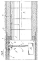
- FIG. 1 shows the end 1 of a tunnel boring machine (not shown) on the left and, to the right, a front formwork 2 with the subsequent tunnel formwork consisting of a plurality of tunnel formwork elements 3. It can also be a sliding formwork.
- the tunnel tube 5 can also be seen in the surrounding mountains 4. For reasons of clarity, only the longitudinal sections have been shown in FIG. 1, but not the projections of the named components and units on the drawing plane.
- Lining concrete is pumped into the tunnel lining ring space 6 between the tunnel formwork elements 3 and mountains 4.
- the feed line 7 shown in FIG. 1 is used for this purpose.
- a special feed line section 8 can be seen in the feed line 7. It is a special pipe section which is set up in such a way that in its area the lining concrete in the feed line 7 by supplying electrical Energy can be heated. For this purpose, heat is generated in the volume elements of the concrete and the lining concrete is thereby thoroughly heated before entering the tunnel lining ring space 6, to a temperature of 40 to 70 ° C., preferably 50 to 60 ° C.
- the feed line section 8, in which the heating takes place, is practically immediately before the entry of the lining concrete in the tunnel lining ring space 6. It goes without saying that fittings and measuring devices can be arranged in the feed line 7, 8 and between 8 and the front formwork 2.
- an electrolytic heating device 9 can be seen with a non-conductive tube section 8 as the feed line section of the feed line 7 and electrodes 11, 12 installed therein, which bear against the phases of a technical alternating current and bear against the inner wall section 10 of the tube section connected to the corresponding phases 13, 14 of a power-adjustable transformer 15, which was shown in FIG. 1.
- the electrodes 11, 12 lie opposite one another in the tube section.
- three electrodes would be provided and offset from one another by 120 °.
- a concrete cone is allowed to flow apart on a shock table.
- the diameter of the poured concrete is the spread.
- the concrete with which, according to the invention, is used as a lining concrete has the specified special features in the "workability” and "hardening” areas. So far the concrete be adjusted according to the prevailing teaching of concrete technology. This setting surprisingly has the consequence that in the first minutes up to the time period of about 10 to 30 minutes, a disruptive stiffening does not occur even after the introduction of the electrical energy until the preset temperature has been set. At a temperature of 20 ° C, the curve, which is provided in FIG.
Landscapes
- Engineering & Computer Science (AREA)
- Architecture (AREA)
- Structural Engineering (AREA)
- Mining & Mineral Resources (AREA)
- Civil Engineering (AREA)
- Life Sciences & Earth Sciences (AREA)
- General Life Sciences & Earth Sciences (AREA)
- Geochemistry & Mineralogy (AREA)
- Geology (AREA)
- Mechanical Engineering (AREA)
- Lining And Supports For Tunnels (AREA)
Claims (2)
- Procédé pour fabriquer un revêtement de tunnel en béton de revêtement au cours du creusement du tunnel avec une machine à creuser des tunnels, par exemple une taupe à bouclier, selon lequel un espace annulaire (6) pour le revêtement du tunnel, fermé du côté de la taupe par un coffrage frontal (2) est agencé à l'aide d'un coffrage de tunnel (3) qui, après un durcissement suffisant du béton de revêtement, est déplacé en fonction de l'agencement du tunnel, au moins une conduite d'amenée de béton (7), dans laquelle le béton de revêtement est chauffé dans la zone du coffrage frontal (2) entre des électrodes, par introduction directe d'une énergie électrique dans le béton de revêtement, débouche dans l'espace annulaire (6) pour le revêtement du tunnel, un béton de revêtement, qui peut être mis en oeuvre pendant plus de deux heures à une température d'environ 20°C et qui ne peut plus être mis en oeuvre après réchauffement à une température de l'ordre de 40 à 70°C, au bout de 10 à 30 minutes, est introduit dans l'espace annulaire (6) pour le revêtement du tunnel, et le béton coulant situé dans la conduite d'amenée de béton (7,8) est chauffé à une température située dans la gamme indiquée, au moyen de l'introduction de l'énergie électrique.
- Procédé selon la revendication 1, selon lequel on met en oeuvre un béton de revêtement qui, après échauffement à une température d'environ 50°C, ne peut plus être mis en oeuvre au bout d'environ 15 minutes.
Applications Claiming Priority (4)
| Application Number | Priority Date | Filing Date | Title |
|---|---|---|---|
| DE19863622203 DE3622203A1 (de) | 1986-03-26 | 1986-07-02 | Verfahren zur herstellung einer tunnelauskleidung und vorrichtung zur durchfuehrung des verfahrens |
| DE3622203 | 1986-07-02 | ||
| DE3644532 | 1986-12-24 | ||
| DE19863644532 DE3644532A1 (de) | 1986-03-10 | 1986-12-24 | Verfahren zur herstellung einer tunnelauskleidung aus auskleidungsbeton und vorrichtung fuer die durchfuehrung des verfahrens |
Publications (3)
| Publication Number | Publication Date |
|---|---|
| EP0254835A1 EP0254835A1 (fr) | 1988-02-03 |
| EP0254835B1 EP0254835B1 (fr) | 1990-10-03 |
| EP0254835B2 true EP0254835B2 (fr) | 1996-05-01 |
Family
ID=25845172
Family Applications (1)
| Application Number | Title | Priority Date | Filing Date |
|---|---|---|---|
| EP19870107717 Expired - Lifetime EP0254835B2 (fr) | 1986-07-02 | 1987-05-27 | Procédé pour la fabrication d'un revêtement de tunnel en béton de revêtement et dispositif pour sa mise en oeuvre |
Country Status (3)
| Country | Link |
|---|---|
| EP (1) | EP0254835B2 (fr) |
| JP (1) | JPS6367398A (fr) |
| DE (1) | DE3765341D1 (fr) |
Families Citing this family (3)
| Publication number | Priority date | Publication date | Assignee | Title |
|---|---|---|---|---|
| GB2291099B (en) * | 1994-07-02 | 1997-12-17 | George Henry Slade | Tunnel lining |
| JP4750568B2 (ja) * | 2006-01-30 | 2011-08-17 | 佐藤工業株式会社 | トンネル合流部の構築方法およびトンネル合流部構造 |
| CN109339817B (zh) * | 2018-08-30 | 2020-07-03 | 上海隧道工程有限公司 | 用于机械法联络通道曲面管片的切削控制方法 |
Family Cites Families (6)
| Publication number | Priority date | Publication date | Assignee | Title |
|---|---|---|---|---|
| JPS5213652A (en) * | 1975-07-23 | 1977-02-02 | Hitachi Ltd | Thickkfilm capacitor |
| DE2636530A1 (de) * | 1976-07-15 | 1978-05-03 | Fisher | Erwaermung von halbleitern |
| DE2813462A1 (de) * | 1978-03-29 | 1979-10-11 | Bonnkirch Ray J | Vorrichtung zum vorwaermen von beton vor dem vergiessen |
| FR2461425A1 (fr) * | 1979-07-06 | 1981-01-30 | Electricite De France | Dispositif de chauffage electrique, en continu, d'un produit liquide ou pateux electriquement conducteur, notamment du beton |
| FR2485860A2 (fr) * | 1980-06-25 | 1981-12-31 | Electricite De France | Dispositif de chauffage electrique, en continu, d'un produit liquide ou pateux electriquement conducteur, notamment du beton |
| DE3508966A1 (de) * | 1985-03-13 | 1986-09-25 | Hochtief Ag Vorm. Gebr. Helfmann, 4300 Essen | Verfahren und vorrichtung zur herstellung einer tunnelauskleidung aus beton im zuge des tunnelvortriebs mit einer tunnelvortriebsmaschine |
-
1987
- 1987-05-27 DE DE8787107717T patent/DE3765341D1/de not_active Expired - Fee Related
- 1987-05-27 EP EP19870107717 patent/EP0254835B2/fr not_active Expired - Lifetime
- 1987-07-01 JP JP62162537A patent/JPS6367398A/ja active Granted
Also Published As
| Publication number | Publication date |
|---|---|
| JPH0562200B2 (fr) | 1993-09-07 |
| EP0254835B1 (fr) | 1990-10-03 |
| EP0254835A1 (fr) | 1988-02-03 |
| DE3765341D1 (de) | 1990-11-08 |
| JPS6367398A (ja) | 1988-03-26 |
Similar Documents
| Publication | Publication Date | Title |
|---|---|---|
| EP0789006B1 (fr) | Mélange sec pour une suspension de ciment, procédé pour sa fabrication et dispositif pour la mise en oeuvre du procédé | |
| DE3415782A1 (de) | Verfahren und vorrichtung zum erzeugen von lufthaltigen zementartigen verbindungen | |
| DE4118537C1 (fr) | ||
| AT406704B (de) | Verfahren und vorrichtung zum verlegen einer unterirdischen rohrleitung aus kunststoff | |
| EP0254835B2 (fr) | Procédé pour la fabrication d'un revêtement de tunnel en béton de revêtement et dispositif pour sa mise en oeuvre | |
| EP0584573A1 (fr) | Dispositif pour la fabrication de mortier apte à être pompé sur le chantier | |
| DE3508966A1 (de) | Verfahren und vorrichtung zur herstellung einer tunnelauskleidung aus beton im zuge des tunnelvortriebs mit einer tunnelvortriebsmaschine | |
| DE3644532C2 (fr) | ||
| DE4427661C2 (de) | Zementbeimischung, Zementzusammensetzung und Verwendung der Zementzusammensetzung | |
| DE3622203C2 (fr) | ||
| DE102010024975A1 (de) | Verfahren und Vorrichtung zur Herstellung von Baustoffmischungen und Baustoffmischungen für MgO-Beton sowie Verfahren zum Aufbringen von Baustoffmischungen auf zu verschließenden Hohlräumen und Grubenbauen im Salzgestein | |
| EP0154208A1 (fr) | Procédé de percement par bouclier avec pose d'un tubage en béton coulé et dispositif pour sa réalisation | |
| DE3136737C2 (de) | Verfahren zur Herstellung kunststoffhaltiger Spritzbetone | |
| DE3340810C2 (de) | Verfahren zum Herstellen von prismatischen Bauteilen aus Stahlbeton, insbesondere Stahlbetonstützen sowie Vorrichtung zum Durchführen des Verfahrens | |
| EP0931909A1 (fr) | Dispositif pour comprimer une chambre annulaire avec mortier, entre l'élément de cuvelage et le terrain | |
| AT409773B (de) | Verfahren zur herstellung von pfählen und solchermassen hergestellte pfähle | |
| DE2758475A1 (de) | Verfahren und vorrichtung zum herstellen von rohrfoermigen gegenstaenden aus spritzbeton mit einer gleichmaessig verteilten bewehrung und nach diesem verfahren hergestelltes produkt | |
| CH669784A5 (fr) | ||
| DE10154201A1 (de) | Verfahren zur Bewehrung von Bauteilen aus dem Tiefbau durch Fasern, hierfür geeignete Vorrichtung und derart hergestellte Bauteile | |
| AT397244B (de) | Hydraulisches bindemittel für beton oder mörtel | |
| AT522502B1 (de) | Verfahren zur Betoneinbringung bei einer horizontalen Gleitbauweise in Ortbetonbauweise, Vorrichtung zur Herstellung eines horizontalen Betonelements | |
| EP1243752B1 (fr) | Elément de cuvelage de revêtement de tunnels, notamment à haute performance | |
| DE2648477C3 (de) | Verbundausbau für Bergbauschächte | |
| EP2570397A2 (fr) | Béton projeté | |
| DE3328898A1 (de) | Trockenmischung fuer einen estrich, sowie verfahren und vorrichtung zu seiner herstellung |
Legal Events
| Date | Code | Title | Description |
|---|---|---|---|
| PUAI | Public reference made under article 153(3) epc to a published international application that has entered the european phase |
Free format text: ORIGINAL CODE: 0009012 |
|
| 17P | Request for examination filed |
Effective date: 19870623 |
|
| AK | Designated contracting states |
Kind code of ref document: A1 Designated state(s): AT BE CH DE ES FR GB GR IT LI LU NL SE |
|
| RBV | Designated contracting states (corrected) |
Designated state(s): BE DE FR GB NL |
|
| TCNL | Nl: translation of patent claims filed | ||
| GBC | Gb: translation of claims filed (gb section 78(7)/1977) | ||
| EL | Fr: translation of claims filed | ||
| 17Q | First examination report despatched |
Effective date: 19881028 |
|
| GRAA | (expected) grant |
Free format text: ORIGINAL CODE: 0009210 |
|
| AK | Designated contracting states |
Kind code of ref document: B1 Designated state(s): BE DE FR GB NL |
|
| REF | Corresponds to: |
Ref document number: 3765341 Country of ref document: DE Date of ref document: 19901108 |
|
| GBT | Gb: translation of ep patent filed (gb section 77(6)(a)/1977) | ||
| ET | Fr: translation filed | ||
| PGFP | Annual fee paid to national office [announced via postgrant information from national office to epo] |
Ref country code: NL Payment date: 19910531 Year of fee payment: 5 |
|
| PLBI | Opposition filed |
Free format text: ORIGINAL CODE: 0009260 |
|
| 26 | Opposition filed |
Opponent name: DYCKERHOFF & WIDMANN AG Effective date: 19910702 |
|
| NLR1 | Nl: opposition has been filed with the epo |
Opponent name: DYCKERHOFF & WIDMANN AG. |
|
| PG25 | Lapsed in a contracting state [announced via postgrant information from national office to epo] |
Ref country code: NL Effective date: 19921201 |
|
| NLV4 | Nl: lapsed or anulled due to non-payment of the annual fee | ||
| PGFP | Annual fee paid to national office [announced via postgrant information from national office to epo] |
Ref country code: GB Payment date: 19960227 Year of fee payment: 10 |
|
| PUAH | Patent maintained in amended form |
Free format text: ORIGINAL CODE: 0009272 |
|
| STAA | Information on the status of an ep patent application or granted ep patent |
Free format text: STATUS: PATENT MAINTAINED AS AMENDED |
|
| PGFP | Annual fee paid to national office [announced via postgrant information from national office to epo] |
Ref country code: BE Payment date: 19960322 Year of fee payment: 10 |
|
| 27A | Patent maintained in amended form |
Effective date: 19960501 |
|
| AK | Designated contracting states |
Kind code of ref document: B2 Designated state(s): BE DE FR GB NL |
|
| PGFP | Annual fee paid to national office [announced via postgrant information from national office to epo] |
Ref country code: FR Payment date: 19960515 Year of fee payment: 10 |
|
| GBTA | Gb: translation of amended ep patent filed (gb section 77(6)(b)/1977) |
Effective date: 19960501 |
|
| ET3 | Fr: translation filed ** decision concerning opposition | ||
| PGFP | Annual fee paid to national office [announced via postgrant information from national office to epo] |
Ref country code: DE Payment date: 19970429 Year of fee payment: 11 |
|
| PG25 | Lapsed in a contracting state [announced via postgrant information from national office to epo] |
Ref country code: GB Effective date: 19970527 |
|
| PG25 | Lapsed in a contracting state [announced via postgrant information from national office to epo] |
Ref country code: BE Effective date: 19970531 |
|
| BERE | Be: lapsed |
Owner name: HOCHTIEF A.G. VORM. GEBR. HELFMANN Effective date: 19970531 |
|
| GBPC | Gb: european patent ceased through non-payment of renewal fee |
Effective date: 19970527 |
|
| PG25 | Lapsed in a contracting state [announced via postgrant information from national office to epo] |
Ref country code: FR Free format text: LAPSE BECAUSE OF NON-PAYMENT OF DUE FEES Effective date: 19980130 |
|
| REG | Reference to a national code |
Ref country code: FR Ref legal event code: ST |
|
| PG25 | Lapsed in a contracting state [announced via postgrant information from national office to epo] |
Ref country code: DE Free format text: LAPSE BECAUSE OF NON-PAYMENT OF DUE FEES Effective date: 19990302 |
|
| APAH | Appeal reference modified |
Free format text: ORIGINAL CODE: EPIDOSCREFNO |