EP0255129A2 - Gerät zum Abschälen eines Films - Google Patents
Gerät zum Abschälen eines Films Download PDFInfo
- Publication number
- EP0255129A2 EP0255129A2 EP87111013A EP87111013A EP0255129A2 EP 0255129 A2 EP0255129 A2 EP 0255129A2 EP 87111013 A EP87111013 A EP 87111013A EP 87111013 A EP87111013 A EP 87111013A EP 0255129 A2 EP0255129 A2 EP 0255129A2
- Authority
- EP
- European Patent Office
- Prior art keywords
- film
- translucent resin
- detecting member
- detecting
- resin film
- Prior art date
- Legal status (The legal status is an assumption and is not a legal conclusion. Google has not performed a legal analysis and makes no representation as to the accuracy of the status listed.)
- Withdrawn
Links
Images



Classifications
-
- G—PHYSICS
- G03—PHOTOGRAPHY; CINEMATOGRAPHY; ANALOGOUS TECHNIQUES USING WAVES OTHER THAN OPTICAL WAVES; ELECTROGRAPHY; HOLOGRAPHY
- G03F—PHOTOMECHANICAL PRODUCTION OF TEXTURED OR PATTERNED SURFACES, e.g. FOR PRINTING, FOR PROCESSING OF SEMICONDUCTOR DEVICES; MATERIALS THEREFOR; ORIGINALS THEREFOR; APPARATUS SPECIALLY ADAPTED THEREFOR
- G03F7/00—Photomechanical, e.g. photolithographic, production of textured or patterned surfaces, e.g. printing surfaces; Materials therefor, e.g. comprising photoresists; Apparatus specially adapted therefor
- G03F7/16—Coating processes; Apparatus therefor
- G03F7/161—Coating processes; Apparatus therefor using a previously coated surface, e.g. by stamping or by transfer lamination
-
- B—PERFORMING OPERATIONS; TRANSPORTING
- B29—WORKING OF PLASTICS; WORKING OF SUBSTANCES IN A PLASTIC STATE IN GENERAL
- B29C—SHAPING OR JOINING OF PLASTICS; SHAPING OF MATERIAL IN A PLASTIC STATE, NOT OTHERWISE PROVIDED FOR; AFTER-TREATMENT OF THE SHAPED PRODUCTS, e.g. REPAIRING
- B29C63/00—Lining or sheathing, i.e. applying preformed layers or sheathings of plastics; Apparatus therefor
- B29C63/0004—Component parts, details or accessories; Auxiliary operations
- B29C63/0013—Removing old coatings
-
- B—PERFORMING OPERATIONS; TRANSPORTING
- B65—CONVEYING; PACKING; STORING; HANDLING THIN OR FILAMENTARY MATERIAL
- B65C—LABELLING OR TAGGING MACHINES, APPARATUS, OR PROCESSES
- B65C9/00—Details of labelling machines or apparatus
- B65C9/0006—Removing backing sheets
-
- B—PERFORMING OPERATIONS; TRANSPORTING
- B65—CONVEYING; PACKING; STORING; HANDLING THIN OR FILAMENTARY MATERIAL
- B65H—HANDLING THIN OR FILAMENTARY MATERIAL, e.g. SHEETS, WEBS, CABLES
- B65H41/00—Machines for separating superposed webs
-
- Y—GENERAL TAGGING OF NEW TECHNOLOGICAL DEVELOPMENTS; GENERAL TAGGING OF CROSS-SECTIONAL TECHNOLOGIES SPANNING OVER SEVERAL SECTIONS OF THE IPC; TECHNICAL SUBJECTS COVERED BY FORMER USPC CROSS-REFERENCE ART COLLECTIONS [XRACs] AND DIGESTS
- Y10—TECHNICAL SUBJECTS COVERED BY FORMER USPC
- Y10T—TECHNICAL SUBJECTS COVERED BY FORMER US CLASSIFICATION
- Y10T156/00—Adhesive bonding and miscellaneous chemical manufacture
- Y10T156/11—Methods of delaminating, per se; i.e., separating at bonding face
- Y10T156/1105—Delaminating process responsive to feed or shape at delamination
-
- Y—GENERAL TAGGING OF NEW TECHNOLOGICAL DEVELOPMENTS; GENERAL TAGGING OF CROSS-SECTIONAL TECHNOLOGIES SPANNING OVER SEVERAL SECTIONS OF THE IPC; TECHNICAL SUBJECTS COVERED BY FORMER USPC CROSS-REFERENCE ART COLLECTIONS [XRACs] AND DIGESTS
- Y10—TECHNICAL SUBJECTS COVERED BY FORMER USPC
- Y10T—TECHNICAL SUBJECTS COVERED BY FORMER US CLASSIFICATION
- Y10T156/00—Adhesive bonding and miscellaneous chemical manufacture
- Y10T156/19—Delaminating means
- Y10T156/1906—Delaminating means responsive to feed or shape at delamination
Definitions
- This invention relates to a film peeling technique, and more particularly to a technique which can be employed effectively to peel off a protective film stuck to the surface of a substrate or panel.
- a wiring having a prscribed pattern is formed from copper on one or both sides of an insulating board.
- An object of the present invention is to obtain a film peeling apparatus which can certainly and instantly peel the thin film from a panel.
- a film peeling apparatus is intended for the purpose of peeling off a film stuck onto a base by raising one end thereof.
- the film peeling apparatus comprises a projection formed detecting member for detecting the end of the film stuck onto the base and an oscillating device for oscillating the projection-formed detecting member upon detection of the end of the film by the detecting member to thereby raise the end of the film.
- the film peeling apparatus includes a fluid injection device for peeling the film off the base by sending a jet of fluid to the end of the film thus raised by the oscillating device.
- the end of a film is searched out by the projected-form detecting member and the oscillating device operating on receiving a detection signal generated from the detection member is used to oscillate the projected detecting member located at the end of the film, so that the end of the film is raised certainly.
- a jet of fluid is supplied by the fluid injection device to the end of the thus surely raised film to ensure that the film is peeled off instantly.
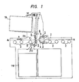
- Fig. l is a schematic side view showing a construction of an apparatus for peeling off a protective film from a board for a printed circuit board, according to the present invention.
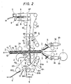
- Fig. 2 is an enlarged side view of the principal portion of Fig. l.
- the mechanism for conveying a board in the film peeling apparatus mainly comprises conveyance driving rollers 2 for conveying a board l, as shown in Figs. l and 2.
- a film raising mechanism 3 a fluid injection mechanism 4, a peel angle setting plate (auxiliary peeling plate) 5 and a film delivery mechanism (film conveyance apparatus) 6 are arranged along the conveyance path A-A.
- a conductive layer lB of copper or the like is formed on one or both sides of an insulated substrate lA, as shown in Fig. 2.
- a laminate consisting of a photosensitive resin layer lC and a translucent resin film (or a protective film) lD is thermally formed on the conductive layer lB of the board l under pressure.
- the photosensitive resin layer lC has been exposed to light in a predetermined circuit pattern.
- the film raising device 3 and the fluid injection device 4 are constructed as shown in Fig. 3 where the construction of them are concretely shown.
- the film raising device 3 mainly comprises a project projection-formed detecting member 3A and an oscillating device 3B.
- the capacitive detecting device when the end of the laminate is detected by the detecting member 3A, the capacitive detecting device, for instance, outputs a detection signal. With receiving the signal, the oscillating device 3B actuates the electromagnet 3Bd and oscillates the projected detecting member 3A.
- the film raising device 3 is supported to a moving member 3D via a rotary shaft 3C which is fitted to the oscillating device 3B rotatably in directions of arrows D and D ⁇ .
- the film raising device 3 is made rotatable, by a driving source such as an air cylinder, a hydraulic cylinder and a solenoid (not shown), in direction of arrow D with respect to the moving member 3D.
- the moving member 3D supporting the film raising device 3 is made movable, by a linear head 3E, in directions of arrow E and E ⁇ which are the same with and opposite to the base conveying direction, respectively, of the apparatus body.
- the moving member 3D may be driven by an air cylinder, hydraulic cylinder or solenoid, in place of the linear head.
- one or a plurality of film raising devices 3 are arranged in a direction across the base conveying direction (in the widthwise direction of the board l), on both surface sides of the board l.
- the film raising device 3 should preferably be placed in at least three places in the direction across the base conveying direction.
- one or a plurality of film raising devices 3 may be installed respectively on each surface side of the board l in such a manner that they are arranged in the same direction as the base conveying direction or at the corners of the board l.
- the fluid injection device 4 comprises, as shown in Figs. 3 and 5, a fluid injection nozzle 4A and a fluid supply member 4B which are integrated with the film raising device 3.
- the fluid injection nozzle 4A having the projection-formed detecting member 3A therein is capable of accurately guiding the fluid injection outlet to the end of the laminate thus raised and setting the injection outlet considerably close thereto, to ensure that the fluid F is sent to the end of the raised laminate.
- the fluid injection nozzle 4A is made of insulating material such as hard plastic so that the detecting member 3A is prevented from malfunctioning in detecting the position of the end of the laminate even if the detecting member 3A comes into contact with the injection nozzle 4A. Moreover, the fluid injection nozzle 4A may be formed such that its portion which is apt to contact the detecting member 3A is formed of insulating material.
- the fluid injection device 4 thus constructed moves as the film raising device 3 moves when the rotary shaft 3C and linear head 3E are operated.
- the moving member 3D is moved by the linear head in direction of arrow E (which is the same direction as the base conveying direction) while the projected-form detecting member 3A is kept contacting the surface of the translucent resin film lD.
- the detecting member 3A is separated from the surface of the translucent resin film lD and reaches the surface of the conductive layer lB, i.e., when the detecting member 3A is positioned at the end of the laminate, the capacitance detected by a capacitive detecting device (not shown) is changed, so that the position of the end of the laminate is detected by the capacitive detecting device.
- the capacitive detecting device outputs a detection signal, and with the signal, the operation of the linear head 3E is stopped.
- the end of the laminate is detected when the capacitance of the board l changes.
- the oscillating device 3B starts oscillating the detecting member 3A in direction of arrow C, on receiving the detection signal from the capacitive detecting device.
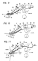
- part of the translucent resin film lD is, as shown in Fig. 9, raised from the photosensitive resin layer lC at the end of the laminate.
- a jet of pressurized fluid F is sent from the fluid injection nozzle 4A to the portion of the end of the laminate thus raised, i.e., to the gap between the photosensitive resin layer lC and the translucent resin film lD and, as shown in fig. l0, the operation of peeling the translucent resin film lD off is started.
- the rotary shaft thus turned in direction of arrow D ⁇ moves and makes the tip of the projection-formed detecting member 3A separate from the photosensitive resin layer lC, whereas the fluid F is continuously sent to the peel position to peel off the translucent resin film lD (ld) continuously.
- the injection of a jet of fluid F to the peel position is continuously conducted with moving the moving member 3D in direction of arrow E ⁇ using the linear head 3E, or with carrying the board l in a direction of arrow A using the conveyance driving rollers 2 Or the injection of the fluid is conducted, with moving both the moving member 3D and the board l.
- the projected form detecting member 3A operates both as a contact element for detecting the end of the laminate and as a projection member for raising the end of the laminate whereby the space required for the film raising device 3 to surely raise the end of the laminate can be reduced, to make the film peeling apparatus compact.
- the projected-form detecting member 3A arranged to be oscillated in the fluid injection nozzle 4A by the oscillating device 3B makes it possible to accurately guide the outlet of the fluid injection nozzle 4A to the position sufficiently close to the end of the laminate raised by the detecting member 3A. Consequently, the peel effect is improved to assure that the translucent resin films lD are efficiently peeled off from the photosensitive resin layers lC.
- the outlets of the fluid injection nozzles 4A can be guided accurately substantially close to the end of the laminates, irrespective of the thickness of the board l.
- the end of the laminate can be raised by the projected-form detecting member 3A which is simple in construction.
- the projected-form detecting members 3A are provided in the board carrying passage, it makes possible to perform the operation of automatically peeling off the ends of the laminates.
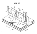
- the front end ld of the translucent resin film in the conveyance direction thereof peeled off by the fluid injection mechanism 4 is stuck to the peel angle setting plate (auxiliary peeling plate) 5 by the fluid pressure, and the peel position and the peel angle ⁇ for peel direction is set.
- the translucent resin film ld is shown by one-dot-and-dash line of Figs. 2 and 12.
- a peel angle ⁇ is formed between the translucent resin film lD stuck onto the board l and the direction in which the translucent resin film ld thus raised up from the board l is discharged.
- a peel angle setting plate 5 is arranged substantially perpendicular to the board l.
- the peel angle at the peel position should be preferably set obtuse with respect to the carrying direction of the board l, i.e. the direction of arrow A.
- the peel angle setting plate 5 having the peel angle ⁇ of about a right angle the peel angle of the peeling direction of the translucent resin film ld is about 90 degrees.
- the carrying speed of the board l is made slightly higher than the discharge speed of the translucent resin film ld, so that the peel angle at the peel position is made substantially obtuse.
- the peel angle setting plate 5 is installed such that the front end of the peel angle setting plate 5 on the peeling side at the peel position is apart from the translucent resin film lD stuck to the board l and such that the setting plate may not brush with the resin film lD to prevent the photosensitive resin layer lC from being damaged or broken down. Furthermore, the peel angle setting plate 5 is movably arranged so that the front end of the peel angle setting plate 5 sticks tightly to the translucent resin film lD during the time the fluid is being injected, for preventing reduction of the peel effect. Since the peel angle setting plate 5 is movable, an accurate peeling position can ensurely obtained in corresponding to a thickness of the board l, even if the boards l different in its thickness from one another are conveyed.
- the peel angle setting plate 5 may be moved or transferred by an air or hydraulic cylinder. Moreover, the front end of the peel angle setting plate 5 is in a circular arc form with its curvature radius being small, that is, its curvature radius being less than 3 mm.
- the peel angle setting plate 5 has its front end located closer to the board l conveyed than the thin film delivery mechanism 6.
- the peel angle setting plate 5 extends in the peel direction (film delivery direction) with a predetermined length.
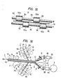
- the peel angle setting plate 5 extends in a crosswise direction of the peeled film crossing the film peeling direction with its length being enough to cover the width of the conveyance path of the board l or the fluid injection width.
- the peel angle setting plate 5, as the direction of the fluid flown is shown by an arrow K in Fig. 12, is capable of increasing the peeling effects, by preventing the fluid from being blown to the rear side of the peel angle setting plate 5 and is capable of increasing the adhesion of the peeled translucent resin film ld to the peel angle setting plate 5.
- the peel angle setting plate 5 is able to stabilize the peel position and apply uniform peeling force to the translucent resin film lD. Accordingly, the peel angle setting plate 5 prevents the peel position from shifting when the translucent resin film lD is being peeled off and prevents peel stress from distorting and the photosensitive resin layer lC from being damaged or broken.
- the peeling angle setting plate 5 is provided with a through-hole 5B at the position to which the translucent resin film ld peeled is stuck.
- the through-hole 5B is used for detecting the film peeled.
- the through-hole 5B is arranged so that the detection light for an optical sensor 5C can pass through the hole 5B.
- the base is discharged from the conveyance passage, after the peeling is performed.
- the translucent resin film ld stuck to the peel angle setting plate 5 by the fluid injection mechanism 4 is, as shown in Figs. l, 2 and 13, carried out by the film carrying out mechanism (thin film conveyance mechanism) 6 while the thin film is being peeled off.
- the thin film conveyance mechanism 6 comprises an upper conveyor belt mechanism and a lower conveyor belt mechanism installed on both sides of the board l, respectively.
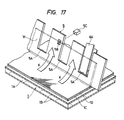
- the upper conveyor belt mechanism consists of, as shown in Fig. 13 in detail, fixed conveyor belts 6A, 6C, 6D, 6E, 6F and a moving conveyor belts 6B.
- the fixed conveyor belt 6A consists of a roller 6Aa supported by a driven shaft I, a roller 6Ab supported by a driving shaft II and a belt 6a wound on the rollers 6Aa and 6Ab.
- the moving conveyor belt 6B consists of a roller 6Ba supported by a driven shaft III, a roller 6Bb supported by a driving shaft IV and a belt 6b wound on the rollers 6Ba and 6Bb.
- the moving conveyor belt 6B is rotated on the driving shaft IV in the direction of an arrow L as shown in Fig. 2.
- the moving conveyor belt 6B facilitates the adhesion of the peeled translucent resin film ld to the peel angle setting plate 5 and is capable of carrying the translucent resin film ld by sandwiching it between the moving conveyor belt 6B and the fixed conveyor belt 6A.
- the operation of sandwiching the translucent resin film ld between the fixed and moving conveyor belts 6A and 6B is conducted through a cut 5A provided in the peel angle setting plate 5, as shown in Fig. 12.
- the fixed conveyor belt 6C consists of a roller 6Ca supported by the driving shaft II, a roller 6Cb supported by a driven shaft V and a belt 6c wound on rollers 6Ca, 6Cb.
- the fixed conveyor belt 6D consists of a roller 6Da supported by the driven shaft IV, a roller 6Db supported by the driven shaft VI, a roller 6Dc supported by a driven shaft VII, a roller 6Dd supported by a driven shaft VIII, a roller 6De supported by the driven shaft V and a belt 6d wound on rollers 6Da to 6De.
- the fluid spray mechanism 8 comprises a pipe with outlets from which the fluid is jetted out, the outlets being provided between the respective two conveyor belts 6E and 6E (6F and 6F, 6G and 6G and 6H and 6H) disposed adjacent to each other in the crosswise direction of the film ld being carried crossing the conveyance direction.
- gas such as pressurized air or inert gas or the like and liquid such as water or the like may be used.
- a static eliminator (not shown) for reducing electrification of the translucent resin film ld is installed close to the fluid sprayer 8.
- static eliminators 10 and ion dispersion devices ll are installed close to the fixed conveyor belt 6A and the moving conveyor belt 6H, respectively.
- the static eliminator 10 is used to discharge ions in order that the static electrification of the translucent resin film ld to be occurred while the film ld is peeled off or carried can be reduced.
- the ion dispersion device ll disperses the ions discharged by the static eliminator 10, in order to efficiently reduce the static electrification of the film ld.
- the device ll disperses ions, using pressurized fluid such as air, for example.
- the film peeling apparatus of the present invention may be constructed such that the angle ⁇ of the peeling direction of the peel angle setting plate 5 is obtuse.
- the peel angle setting plate 5 thus arranged can be set in such a manner that the peel angle at the peel position is obtuse even when the speed of discharging the translucent resin film ld is substantially equal to that of carrying the board l.
- the peel angle setting plate 5 prevents the deflection of the peel position and peel stress of the translucent resin film lD and further prevents the photosensitive resin layer lC from being damaged or broken.
- the projection-form detecting member 3A of the film raising mechanism 3 may be wedge-shaped or plate-shaped instead of projection-shape according to the above embodiment.
- the present invention is also applicable to a film peeling apparatus for peeling off the end of the laminate raised by the projection-formed detecting member 3A of the film raising device 3, by means of an adhesive tape in place of the fluid injection device 4.
- the peel angle setting plate 5 may be constructed such that its peel angle in the peel direction is variable within the range of right to obtuse angle.
- an air cylinder, a hydraulic cylinder or the like is used to make the angle variable.
- the present invention is further applicable to a peeling apparatus for peeling off a protective film stuck to a decorative laminated building material.
- the film peeling apparatus for peeling off the film stuck onto the base by raising one end thereof comprises the projection-form detecting member for detecting the end of the film stuck onto the base and the oscillating device for raising the end of the film by oscillating the projected-form detecting member upon the detection of the detecting member, to ensure that the end of the film is raised instantly by making the projected-form detecting member detect the end of the film and causing the oscillating device operating on the detection signal to oscillate the projected-form detecting member located at the end of the film.
- the fluid injection device for peeling the film off the base by injecting a jet of fluid to the end of the film thus raised by the projected-form detecting member to assure that the jet of fluid is sent to the end of the thus certainly raised film and that the film is peeled off efficiently.
Landscapes
- Physics & Mathematics (AREA)
- General Physics & Mathematics (AREA)
- Engineering & Computer Science (AREA)
- Manufacturing & Machinery (AREA)
- Manufacturing Of Printed Circuit Boards (AREA)
- Photosensitive Polymer And Photoresist Processing (AREA)
- Lining Or Joining Of Plastics Or The Like (AREA)
- Folding Of Thin Sheet-Like Materials, Special Discharging Devices, And Others (AREA)
Applications Claiming Priority (2)
| Application Number | Priority Date | Filing Date | Title |
|---|---|---|---|
| JP181126/86 | 1986-07-31 | ||
| JP61181126A JPS6337352A (ja) | 1986-07-31 | 1986-07-31 | 薄膜剥離装置 |
Publications (2)
| Publication Number | Publication Date |
|---|---|
| EP0255129A2 true EP0255129A2 (de) | 1988-02-03 |
| EP0255129A3 EP0255129A3 (de) | 1989-10-11 |
Family
ID=16095318
Family Applications (1)
| Application Number | Title | Priority Date | Filing Date |
|---|---|---|---|
| EP87111013A Withdrawn EP0255129A3 (de) | 1986-07-31 | 1987-07-29 | Gerät zum Abschälen eines Films |
Country Status (3)
| Country | Link |
|---|---|
| US (1) | US4770737A (de) |
| EP (1) | EP0255129A3 (de) |
| JP (1) | JPS6337352A (de) |
Cited By (6)
| Publication number | Priority date | Publication date | Assignee | Title |
|---|---|---|---|---|
| DE3807952A1 (de) * | 1988-03-10 | 1989-09-21 | Schmid Gmbh & Co Geb | Verfahren und vorrichtung zum abloesen einer abdeckfolie |
| EP0320868A3 (de) * | 1987-12-14 | 1990-11-22 | Somar Corporation | Vorrichtung zur Entfernung einer dünnen Folie |
| EP0452552A3 (en) * | 1990-04-06 | 1992-09-02 | Somar Corporation | Film peeling method and apparatus for practicing same |
| EP0553787A1 (de) * | 1992-01-27 | 1993-08-04 | The Japan Steel Works, Ltd. | Verfahren zur Wiederverwendung von Kunststoffteilen mit Beschichtungen |
| DE4221703A1 (de) * | 1992-07-02 | 1994-01-05 | Anger Electronic Gmbh | Verfahren und Vorrichtung zum ein- oder beidseitigem Abziehen von Schutzfolien |
| CN109941802A (zh) * | 2019-05-06 | 2019-06-28 | 常州纳捷机电科技有限公司 | 一种弹性布料振动上料机构及方法 |
Families Citing this family (15)
| Publication number | Priority date | Publication date | Assignee | Title |
|---|---|---|---|---|
| DE3650181T2 (de) * | 1985-08-16 | 1995-08-24 | Somar Corp | Verfahren und Vorrichtung zum Abziehen eines Films. |
| JPH088292B2 (ja) * | 1987-08-31 | 1996-01-29 | 住友電気工業株式会社 | チップ実装装置 |
| JPH0691153B2 (ja) * | 1987-11-28 | 1994-11-14 | 日東電工株式会社 | 保護フイルムの剥離方法 |
| JPH01292890A (ja) * | 1988-05-20 | 1989-11-27 | Mitsubishi Gas Chem Co Inc | 薄銅張回路基板の製造法 |
| US5240545A (en) * | 1990-10-17 | 1993-08-31 | Somar Corporation | Base plate conveyor |
| US5658416A (en) * | 1994-06-17 | 1997-08-19 | Polaroid Corporation | Method and apparatus for peeling a laminate |
| SG73538A1 (en) * | 1997-08-04 | 2000-06-20 | Matsushita Electric Industrial Co Ltd | Method of heat treating object and apparatus for the same |
| US6500298B1 (en) | 2000-01-14 | 2002-12-31 | Kevin P. Wright | Stripping machine and method |
| JP2002050670A (ja) * | 2000-08-04 | 2002-02-15 | Toshiba Corp | ピックアップ装置及びピックアップ方法 |
| US6752896B2 (en) * | 2001-07-10 | 2004-06-22 | Asm Technology Singapore Pte Ltd | Method of detaching a film of material from a substrate |
| JP4668847B2 (ja) * | 2006-06-07 | 2011-04-13 | 昭和電工パッケージング株式会社 | 帯電防止性に優れたラミネートフィルムの製造方法及び帯電防止性に優れた袋体の製造方法 |
| CN105575833B (zh) * | 2015-12-28 | 2017-11-10 | 华中科技大学 | 一种适用于芯片转移的倒装键合控制方法 |
| TWI650241B (zh) * | 2017-11-30 | 2019-02-11 | 景碩科技股份有限公司 | 撕膜機構 |
| TWI833152B (zh) * | 2022-01-19 | 2024-02-21 | 志聖工業股份有限公司 | 撕膜機及其刮刀機構 |
| CN116495307A (zh) * | 2022-01-19 | 2023-07-28 | 志圣科技(广州)有限公司 | 撕膜机及其刮刀机构 |
Family Cites Families (9)
| Publication number | Priority date | Publication date | Assignee | Title |
|---|---|---|---|---|
| FR2458977A1 (fr) * | 1979-06-13 | 1981-01-02 | Cii Honeywell Bull | Dispositif de demontage non destructif d'un composant electronique modulaire soude par une pluralite de cosses de raccordement sur un substrat |
| JPS5891782A (ja) * | 1981-11-27 | 1983-05-31 | Kansai Seikou Kk | 被着片の接着剤層保護紙を剥離する方法 |
| US4421608A (en) * | 1982-03-01 | 1983-12-20 | International Business Machines Corporation | Method for stripping peel apart conductive structures |
| BE902962A (fr) * | 1984-07-25 | 1985-11-18 | Nitto Electric Ind Co | Procede et appareil de developpement du type a decollement |
| US4685982A (en) * | 1985-04-02 | 1987-08-11 | Label-Aire Inc. | Method and apparatus for sensing sheet-like elements |
| DE3532553C1 (de) * | 1985-09-12 | 1987-03-12 | Loehr & Herrmann Gmbh | Verfahren und Vorrichtung zum Abziehen der Schutzfolie von einer mit belichtetem Fotoresist beschichteten Leiterplatte |
| US4724032A (en) * | 1985-10-02 | 1988-02-09 | Thomas Kay | Sheet separating machine and method |
| EP0223198B1 (de) * | 1985-11-12 | 1992-07-29 | Somar Corporation | Vorrichtung zur Entfernung von auf Platinen aufgeklebten Folien |
| JP2534658B2 (ja) * | 1986-02-24 | 1996-09-18 | ソマ−ル株式会社 | 流体吹付装置を有する薄膜剥離装置 |
-
1986
- 1986-07-31 JP JP61181126A patent/JPS6337352A/ja active Pending
-
1987
- 1987-07-29 EP EP87111013A patent/EP0255129A3/de not_active Withdrawn
- 1987-07-31 US US07/080,356 patent/US4770737A/en not_active Expired - Fee Related
Cited By (9)
| Publication number | Priority date | Publication date | Assignee | Title |
|---|---|---|---|---|
| EP0320868A3 (de) * | 1987-12-14 | 1990-11-22 | Somar Corporation | Vorrichtung zur Entfernung einer dünnen Folie |
| DE3807952A1 (de) * | 1988-03-10 | 1989-09-21 | Schmid Gmbh & Co Geb | Verfahren und vorrichtung zum abloesen einer abdeckfolie |
| EP0452552A3 (en) * | 1990-04-06 | 1992-09-02 | Somar Corporation | Film peeling method and apparatus for practicing same |
| US5312505A (en) * | 1990-04-06 | 1994-05-17 | Somar Corporation | Film peeling method and apparatus for practicing same |
| EP0553787A1 (de) * | 1992-01-27 | 1993-08-04 | The Japan Steel Works, Ltd. | Verfahren zur Wiederverwendung von Kunststoffteilen mit Beschichtungen |
| US5475036A (en) * | 1992-01-27 | 1995-12-12 | The Japan Steel Works, Ltd. | Process for reusing plastic articles with coatings |
| DE4221703A1 (de) * | 1992-07-02 | 1994-01-05 | Anger Electronic Gmbh | Verfahren und Vorrichtung zum ein- oder beidseitigem Abziehen von Schutzfolien |
| CN109941802A (zh) * | 2019-05-06 | 2019-06-28 | 常州纳捷机电科技有限公司 | 一种弹性布料振动上料机构及方法 |
| CN109941802B (zh) * | 2019-05-06 | 2024-01-30 | 常州纳捷机电科技有限公司 | 一种弹性布料振动上料机构及方法 |
Also Published As
| Publication number | Publication date |
|---|---|
| US4770737A (en) | 1988-09-13 |
| EP0255129A3 (de) | 1989-10-11 |
| JPS6337352A (ja) | 1988-02-18 |
Similar Documents
| Publication | Publication Date | Title |
|---|---|---|
| US4770737A (en) | Film peeling apparatus | |
| US4880488A (en) | Film peeling method and apparatus | |
| EP0218873A2 (de) | Vorrichtung zum Abschälen eines Films | |
| EP0237838B1 (de) | Vorrichtung zur Folienentfernung mit einer Flüssigkeitsinjektionseinrichtung | |
| US4798646A (en) | Film peeling apparatus having film end detector | |
| US4867837A (en) | Film peeler | |
| US4961817A (en) | Thin-film releasing apparatus | |
| EP0401702B1 (de) | Verfahren zum Abtrennen eines durch Bonden angehefteten Films von einer Leiterplatte | |
| EP0215397A2 (de) | Vorrichtung zum Abschälen eines Films | |
| US4888080A (en) | Projected press device for raising film | |
| US4908093A (en) | Film conveying apparatus | |
| EP0231938A2 (de) | Folientransportvorrichtung | |
| EP0217150B1 (de) | Vorrichtung zum Abschälen eines Films | |
| JP3963553B2 (ja) | フィルム剥離装置 | |
| JPH0717308B2 (ja) | 薄膜搬送装置 | |
| JP2539788B2 (ja) | 薄膜端部検出装置付薄膜剥離装置 | |
| EP0225505A2 (de) | Vorrichtung zur Folienentfernung | |
| JPH063550B2 (ja) | 薄膜の剥離装置 | |
| JPS6251555A (ja) | 薄膜の剥離装置 | |
| JPH0821766B2 (ja) | 薄膜剥離装置 | |
| JPS62180858A (ja) | 薄膜の剥離装置 | |
| JPH0653536B2 (ja) | 基板搬送装置 | |
| JPS63154582A (ja) | 薄膜の剥離装置 | |
| JPH0829874B2 (ja) | 薄膜剥離装置 | |
| JPS6251556A (ja) | 薄膜の剥離装置 |
Legal Events
| Date | Code | Title | Description |
|---|---|---|---|
| PUAI | Public reference made under article 153(3) epc to a published international application that has entered the european phase |
Free format text: ORIGINAL CODE: 0009012 |
|
| AK | Designated contracting states |
Kind code of ref document: A2 Designated state(s): AT BE CH DE FR GB IT LI NL SE |
|
| PUAL | Search report despatched |
Free format text: ORIGINAL CODE: 0009013 |
|
| AK | Designated contracting states |
Kind code of ref document: A3 Designated state(s): AT BE CH DE FR GB IT LI NL SE |
|
| 17P | Request for examination filed |
Effective date: 19891130 |
|
| 17Q | First examination report despatched |
Effective date: 19920331 |
|
| STAA | Information on the status of an ep patent application or granted ep patent |
Free format text: STATUS: THE APPLICATION HAS BEEN WITHDRAWN |
|
| 18W | Application withdrawn |
Withdrawal date: 19930419 |
|
| RIN1 | Information on inventor provided before grant (corrected) |
Inventor name: SEKI, MITSUHIRO |