EP0255674A2 - Procédé de fabrication d'une bande coulée en métal à structure amorphe et/ou microcristalline - Google Patents
Procédé de fabrication d'une bande coulée en métal à structure amorphe et/ou microcristalline Download PDFInfo
- Publication number
- EP0255674A2 EP0255674A2 EP87110817A EP87110817A EP0255674A2 EP 0255674 A2 EP0255674 A2 EP 0255674A2 EP 87110817 A EP87110817 A EP 87110817A EP 87110817 A EP87110817 A EP 87110817A EP 0255674 A2 EP0255674 A2 EP 0255674A2
- Authority
- EP
- European Patent Office
- Prior art keywords
- tape
- band
- guide channel
- reel
- belt
- Prior art date
- Legal status (The legal status is an assumption and is not a legal conclusion. Google has not performed a legal analysis and makes no representation as to the accuracy of the status listed.)
- Granted
Links
Images


Classifications
-
- B—PERFORMING OPERATIONS; TRANSPORTING
- B65—CONVEYING; PACKING; STORING; HANDLING THIN OR FILAMENTARY MATERIAL
- B65H—HANDLING THIN OR FILAMENTARY MATERIAL, e.g. SHEETS, WEBS, CABLES
- B65H19/00—Changing the web roll
- B65H19/22—Changing the web roll in winding mechanisms or in connection with winding operations
- B65H19/28—Attaching the leading end of the web to the replacement web-roll core or spindle
-
- B—PERFORMING OPERATIONS; TRANSPORTING
- B22—CASTING; POWDER METALLURGY
- B22D—CASTING OF METALS; CASTING OF OTHER SUBSTANCES BY THE SAME PROCESSES OR DEVICES
- B22D11/00—Continuous casting of metals, i.e. casting in indefinite lengths
- B22D11/06—Continuous casting of metals, i.e. casting in indefinite lengths into moulds with travelling walls, e.g. with rolls, plates, belts, caterpillars
- B22D11/0637—Accessories therefor
- B22D11/0694—Accessories therefor for peeling-off or removing the cast product
-
- B—PERFORMING OPERATIONS; TRANSPORTING
- B65—CONVEYING; PACKING; STORING; HANDLING THIN OR FILAMENTARY MATERIAL
- B65H—HANDLING THIN OR FILAMENTARY MATERIAL, e.g. SHEETS, WEBS, CABLES
- B65H2701/00—Handled material; Storage means
- B65H2701/10—Handled articles or webs
- B65H2701/17—Nature of material
- B65H2701/173—Metal
-
- Y—GENERAL TAGGING OF NEW TECHNOLOGICAL DEVELOPMENTS; GENERAL TAGGING OF CROSS-SECTIONAL TECHNOLOGIES SPANNING OVER SEVERAL SECTIONS OF THE IPC; TECHNICAL SUBJECTS COVERED BY FORMER USPC CROSS-REFERENCE ART COLLECTIONS [XRACs] AND DIGESTS
- Y10—TECHNICAL SUBJECTS COVERED BY FORMER USPC
- Y10S—TECHNICAL SUBJECTS COVERED BY FORMER USPC CROSS-REFERENCE ART COLLECTIONS [XRACs] AND DIGESTS
- Y10S242/00—Winding, tensioning, or guiding
- Y10S242/909—Heating or cooling
Definitions
- the invention relates to a device for producing a cast metal strip with an amorphous and / or finely crystalline structure, with a casting device in which molten metal can be applied to a moving heat sink via a casting nozzle, with a reel with winding aids and with between the casting device and the reel arranged guide and transport means, which form a band guide channel and have the band with a gaseous, in particular cooling medium blowing nozzles.
- the strip cast between two casting wheels is placed under tension by a casting wheel directly downstream of the driving rollers in such a way that it is pulled firmly against the cooled jacket of the casting wheel.
- This tension can only be Apply when the tape has sufficient tensile strength due to cooling.
- the belt is also exposed to a gaseous cooling medium on the free side in the area of the casting wheel.
- the belt is guided between the cooling wheel and the take-up reel in a floating manner between the blowing jets by blowing nozzles arranged on both sides of the belt. Blower nozzles are also arranged in the area of the take-up reel and blow a cooling gaseous medium onto the free side of the strip (EP 0 081 175 B1).
- the invention has for its object to provide a winding device of the type mentioned, which enables precise winding at high belt speeds.
- the strip is cooled quickly and without tensile stress, whereby the cooling in the area of the cooling wheel can be reinforced by the gaseous medium of the blowing nozzles arranged in this area.
- the band is pressed against the cooling wheel without tension by the gaseous medium of these blowing nozzles.
- Driver roles loading the tape are not required.
- Even in the area of the second section of the conveyor line, the belt does not have to be subjected to a comparable load to the tensile stress applied by driver rollers. Here it is because of his Own weight or possibly additionally promoted by the flow of the gaseous medium. Because of the narrowness of the guide channel and the preferably supporting flow of the gaseous medium, even very thin belt in the ⁇ range is easily conveyed.
- the tape transfer and tape separating device enables the tape aligned by the catching device to be connected to the take-up reel without interrupting the transport of the tape to the take-up reel.
- the device can be designed in an advantageous manner by a number of features.
- a component of the blowing direction of the blowing nozzles should point in the belt conveying direction.
- cooling wheels with concentrically arranged walls are provided on the first section of the belt guide channel, they should be arranged in the manner of S-roller pairs.
- a number of measures can be provided for detaching and transferring the strip from the casting wheel to the subsequent cooling wheel.
- a tape detaching element can be arranged in the gusset of the jacket of the casting wheel and the tape be. This can consist of a wedge, which is particularly equipped with blow nozzles.
- a pressure roller for the belt should be provided in front of the entrance of the channel formed by the first cooling wheel and its wall. This can be designed as a roller-shaped brush, which is driven by friction rollers running on the jacket of the cooling wheel.
- the flow through the belt guide channel in the conveying direction is preferably generated by a suction device connected to the end of the channel.
- a suction device connected to the end of the channel.
- blowing nozzles in the walls of the channel, the flow direction of which has a flow component pointing towards the end of the channel.
- the catching device preferably consists of a pair of pinch rollers, the rollers of which can be moved apart to catch the band.
- the pinch rollers should be driven to keep the tape taut when connecting to the reel and separator.
- the take-up reel equipped with a tacking agent is assigned a pressing and separating device for the tape on the side opposite the tape guide plane.
- An adhesive coating is suitable as a tack.
- the pressing and separating device which can be moved against the take-up reel preferably consists of a brush and a knife arranged downstream in the direction of travel of the tape, which should be foldable so as not to damage the tape to be wound up. In this configuration it is with the Rewinder possible to use a reversible reel with which the tape can be transferred from the full reel to the empty reel on the fly.
- a rolling device e.g. integrate a reduction or face roller set, preferably on a cooling wheel, in particular the second cooling wheel.
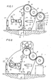
- the belt casting device consists of a container 1 filled with molten metal, a delivery or riser pipe 2 immersed therein, a pouring nozzle 3 and a moving heat sink in the form of a cooled casting wheel 4.
- Belt casting devices in this or a similar embodiment are known. So that due to the centrifugal force acting on the belt 6, the belt 6 does not detach too soon from the jacket of the casting wheel 4, a guide 5, which is equipped with blowing nozzles on the belt, extends over the casting wheel 4 and is arranged concentrically to the jacket of the casting wheel 4 6 blow and thereby press it against the jacket of the casting wheel 4.
- This special design of the casting device is of secondary importance for the invention.
- the invention can also be used in other casting plants, for example in casting devices with two casting wheels or casting devices with nozzles for multi-layer casting. (See German patent applications P 35 21 778.2 and P 36 02 594.1). It is only important that the strip 6 has solidified at the detachment point of the belt 6 from the casting wheel 4. Sufficient tensile strength to apply a tape tension is not yet necessary here.
- a wedge-shaped detaching member 7 is arranged in the gusset between the casing of the casting wheel 4 and the belt 6, which can be equipped with blowing nozzles to support the detachment.
- This detaching element 7 is followed by a brush roller 8 with friction rollers at its ends, which run on the jacket of a first cooling wheel 9.
- the brush roller 8 presses the belt 6 against the jacket of the cooling wheel 9, so that above all the beginning of the tape easily runs into the entrance of a guide channel which is formed by the jacket of the cooling wheel 9 and a guide wall 10 arranged concentrically therewith.
- the first cooling wheel 9 is followed by a second cooling wheel 11 with a correspondingly arranged guide wall 12.
- the belt 6 is guided in an S-shape over the casting wheel 4 and the two cooling wheels 9, 11.
- the guide walls 10, 12 on the cooling wheels 9, 11 are equipped with blowing nozzles, which blow a cooling medium against the belt 6, so that the belt 6 is pressed firmly against the shells of the cooling wheels 9, 11 for the purpose of intensive contact cooling.
- a cooled medium in particular air or an inert gas, is preferably used as the blowing medium. This applies especially to the blowing medium of the nozzles on the casting wheel 4.
- a brush roller 13 is arranged as an additional guide, which is driven by a friction wheel running on the jacket of the cooling wheel 11.
- a flat guide channel 14 adjoins the guide channel 11, 12.
- the width of this guide channel 14 perpendicular to the band plane is smaller than the band width.
- the guide channel 14 can consist of a U-profile, which can be closed by a side cover. By opening the cover and by lateral adjustment, it is possible to release the band 6 guided through the channel 14.
- the strip thickness can be measured with an uninterrupted conveying of the strip 6 with a measuring device 17 which is only indicated.
- a suction device 15 only indicated in the drawing, is connected, which allows a gas flow to flow through the channel from top to bottom.
- the belt 6 which is to be conveyed through the guide channel 14 and is already conveyed on account of its own weight is additionally conveyed.
- a pair of pinch rollers 16 is provided.
- the belt 6 is held by the pinch rollers 16 and in the direction of one Scrap container 18 promoted.
- the guide channel 14 is therefore no longer required, but can be opened and moved out of the guide area.
- a scanning device not shown, the position of the tape 6 can then be detected and used for the winding process to be described.
- each take-up reel 19, 20 is assigned a tape guide roller 22, 23 with lateral spacing, which guides the tape when changing the reel.
- the winding mandrel of each take-up reel 19, 20 has a tacking agent acting on the tape, e.g. an adhesive coating.
- a pressing and separating device 24 is arranged, which, as can be seen from FIGS. 9 and 10, consists of a movable brush-shaped pressing member 25 and a toothed knife 26 which can be folded away . With this pressing and separating device 24, the band 6 can be connected to the take-up reel 19 located in position.
- a respective pivotable pressure roller 27 is assigned to the take-up reel 19 or 20 which is in the change position.
- the guide wall 12 has an opening approximately in the apex of the cooling wheel 11 in which a work roll 29 of a rolling device is arranged.
- the work roll is on intermediate rolls 30, 31 Support roller 32, 33, 34 supported.
- cast metal strip with an armorphic and / or finely crystalline structure is produced in the following manner:
- the molten metal applied to the casting wheel 4 is introduced into the first section of a guide channel formed by cooling wheels 9, 11 and guide walls 10, 12 with the aid of the detaching member 7 and the brush roller 8.
- the belt 6 has a very low strength when leaving the casting wheel 4, but then receives such a strong cooling from the cooling wheels 9, 11 that it is sufficiently firm when leaving the first section of the guide channel to be guided freely. It then passes through the vertically arranged guide channel 14, from which it enters the scrap collecting container 18. This operating phase is shown in Figures 1 and 2.
- the position of the band is detected by means of the scanning device for the position of the band 6, not shown in the drawing.
- the tape 6 and the take-up reel 19 are aligned with one another, for example by moving the take-up reel 19 axially with the tape guide unchanged.
- the pair of pinch rollers 16 is then adjusted in the direction of the take-up reel 19 and the pressing and separating device 24 is moved against the tape 6 in order to attach the tape to the adhesive coating of the mandrel of the take-up reel 19.
- the brush 25 presses the running belt in one Wiping motion.
- the collapsible, spring-mounted knife 26 is folded away by the running belt 6 and therefore does not hinder the movement of the belt either.
- the operating phase of connecting the strip to the reel 19 is shown in FIG. 4.
- the turning reel 21 is pivoted so that the empty take-up reel 20 comes into the position of the full take-up reel 19.
- the conveying of the belt need not be interrupted during this turning process.
- the still wound on the take-up reel 19 is guided after the pivoting process over the guide roller 23, which ensures that the tape 6 is guided substantially vertically past the empty reel 20 for connection to the mandrel.
- the pressing and separating device 24 is actuated again. Before they are actuated, however, the pivotable pressure roller 27 is pressed onto the roll winder 28 so that the bundle 28 remains tightly wound after the band is separated. This operating phase is shown in FIG. 6.
Landscapes
- Engineering & Computer Science (AREA)
- Mechanical Engineering (AREA)
- Continuous Casting (AREA)
Applications Claiming Priority (2)
| Application Number | Priority Date | Filing Date | Title |
|---|---|---|---|
| DE3626638 | 1986-08-06 | ||
| DE19863626638 DE3626638A1 (de) | 1986-08-06 | 1986-08-06 | Vorrichtung zum herstellen eines gegossenen metallbandes mit amorph und/oder feinkristallinem gefuege |
Related Child Applications (1)
| Application Number | Title | Priority Date | Filing Date |
|---|---|---|---|
| EP89104898.5 Division-Into | 1989-03-18 |
Publications (3)
| Publication Number | Publication Date |
|---|---|
| EP0255674A2 true EP0255674A2 (fr) | 1988-02-10 |
| EP0255674A3 EP0255674A3 (en) | 1988-08-31 |
| EP0255674B1 EP0255674B1 (fr) | 1990-03-07 |
Family
ID=6306807
Family Applications (2)
| Application Number | Title | Priority Date | Filing Date |
|---|---|---|---|
| EP89104898A Expired - Lifetime EP0325306B1 (fr) | 1986-08-06 | 1987-07-25 | Dispositif pour couper et attacher une bande de métal à une bobine |
| EP87110817A Expired - Lifetime EP0255674B1 (fr) | 1986-08-06 | 1987-07-25 | Procédé de fabrication d'une bande coulée en métal à structure amorphe et/ou microcristalline |
Family Applications Before (1)
| Application Number | Title | Priority Date | Filing Date |
|---|---|---|---|
| EP89104898A Expired - Lifetime EP0325306B1 (fr) | 1986-08-06 | 1987-07-25 | Dispositif pour couper et attacher une bande de métal à une bobine |
Country Status (4)
| Country | Link |
|---|---|
| US (1) | US4770227A (fr) |
| EP (2) | EP0325306B1 (fr) |
| JP (2) | JPS6372451A (fr) |
| DE (3) | DE3626638A1 (fr) |
Cited By (6)
| Publication number | Priority date | Publication date | Assignee | Title |
|---|---|---|---|---|
| WO1990000100A1 (fr) * | 1988-06-30 | 1990-01-11 | Sundwiger Eisenhütte Maschinenfabrik Grah & Co. | Procede et installation de fabrication d'une bande metallique d'au maximum 10 mm d'epaisseur |
| EP0366005A1 (fr) * | 1988-10-21 | 1990-05-02 | Kawasaki Steel Corporation | Procédé et dispositif pour guider et transférer des bandes métalliques trempées |
| EP0566771A1 (fr) * | 1992-04-22 | 1993-10-27 | Kitamura Kiden Co., Ltd. | Appareil pour couper avec grande précision pour matériel en forme de bande |
| FR2697182A1 (fr) * | 1992-10-26 | 1994-04-29 | Clecim Sa | Dispositif pour le guidage d'une barre de coulée de la sortie de sa roue de coulée jusqu'à l'entrée d'un laminoir. |
| CN106111923A (zh) * | 2016-08-30 | 2016-11-16 | 烟台万隆真空冶金股份有限公司 | 一种基于附壁效应的平面流铸造用节能剥离气刀 |
| WO2017148922A1 (fr) | 2016-03-01 | 2017-09-08 | Sms Group Process Technologies Gmbh | Procédé de séparation du vanadium |
Families Citing this family (6)
| Publication number | Priority date | Publication date | Assignee | Title |
|---|---|---|---|---|
| DE4003067C1 (fr) * | 1990-02-02 | 1991-07-04 | Sundwiger Eisenhuette Maschinenfabrik Grah & Co, 5870 Hemer, De | |
| JP2564500B2 (ja) * | 1990-04-05 | 1996-12-18 | 日立金属株式会社 | アモルファスリボンの巻取方法及び装置 |
| US5040592A (en) * | 1990-06-22 | 1991-08-20 | Armco Inc. | Method and apparatus for separating continuous cast strip from a rotating substrate |
| GB9715358D0 (en) * | 1997-07-21 | 1997-09-24 | Kvaerner Clecim Cont Casting | Method of shearing and guiding metal strip and apparatus therefor |
| EP2298678B1 (fr) * | 2009-09-18 | 2012-02-22 | Reifenhäuser GmbH & Co. Maschinenfabrik | Dispositif d'enroulement |
| US9290348B2 (en) | 2010-12-17 | 2016-03-22 | 3M Innovative Properties Company | Open gap film roll core |
Family Cites Families (12)
| Publication number | Priority date | Publication date | Assignee | Title |
|---|---|---|---|---|
| DE748231C (de) * | 1939-02-25 | 1944-10-30 | Vorrichtung zum Ankleben einer ablaufenden Papierbahn an eine neue Papierrolle | |
| US2942796A (en) * | 1954-08-26 | 1960-06-28 | Monsanto Chemicals | Apparatus for winding thermoplastic film into rolls |
| US3853279A (en) * | 1971-12-23 | 1974-12-10 | D Gerstein | Method and apparatus for forming lightweight web material into a coreless roll |
| US3805652A (en) * | 1972-05-03 | 1974-04-23 | Ind Res & Eng Inc | Automatic tail cutter |
| US4077462A (en) * | 1976-06-30 | 1978-03-07 | Allied Chemical Corporation | Chill roll casting of continuous filament |
| JPS5739030A (en) * | 1980-08-21 | 1982-03-04 | Nippon Steel Corp | Rapid winding apparatus of thin metallic strip |
| JPS5779053A (en) * | 1980-10-31 | 1982-05-18 | Sumitomo Special Metals Co Ltd | Method and device for production of quick cooled material of melt |
| JPS5897468A (ja) * | 1981-12-04 | 1983-06-09 | Kawasaki Steel Corp | 金属薄帯製造方法およびその装置 |
| AT372880B (de) * | 1982-02-16 | 1983-11-25 | Voest Alpine Ag | Verfahren zur herstellung von warmband aus stahl und anlage zur durchfuehrung des verfahrens |
| EP0166884B1 (fr) * | 1982-08-09 | 1988-03-02 | Dai Nippon Insatsu Kabushiki Kaisha | Procédé et dispositif pour relier des rouleaux de bandes de papier se succédant |
| US4557423A (en) * | 1984-07-20 | 1985-12-10 | Electric Power Research Institute, Inc. | Combined clamping and cutting system for moving filament |
| JPS61130164A (ja) * | 1984-11-30 | 1986-06-18 | Mitsubishi Heavy Ind Ltd | フイルム等帯状物の自動切断巻取装置 |
-
1986
- 1986-08-06 DE DE19863626638 patent/DE3626638A1/de active Granted
-
1987
- 1987-07-25 EP EP89104898A patent/EP0325306B1/fr not_active Expired - Lifetime
- 1987-07-25 DE DE8989104898T patent/DE3769660D1/de not_active Expired - Lifetime
- 1987-07-25 DE DE8787110817T patent/DE3761800D1/de not_active Expired - Lifetime
- 1987-07-25 EP EP87110817A patent/EP0255674B1/fr not_active Expired - Lifetime
- 1987-08-05 JP JP62194554A patent/JPS6372451A/ja active Granted
- 1987-08-05 US US06/081,991 patent/US4770227A/en not_active Expired - Fee Related
-
1990
- 1990-05-16 JP JP2124301A patent/JPH038543A/ja active Pending
Cited By (9)
| Publication number | Priority date | Publication date | Assignee | Title |
|---|---|---|---|---|
| WO1990000100A1 (fr) * | 1988-06-30 | 1990-01-11 | Sundwiger Eisenhütte Maschinenfabrik Grah & Co. | Procede et installation de fabrication d'une bande metallique d'au maximum 10 mm d'epaisseur |
| EP0366005A1 (fr) * | 1988-10-21 | 1990-05-02 | Kawasaki Steel Corporation | Procédé et dispositif pour guider et transférer des bandes métalliques trempées |
| EP0566771A1 (fr) * | 1992-04-22 | 1993-10-27 | Kitamura Kiden Co., Ltd. | Appareil pour couper avec grande précision pour matériel en forme de bande |
| US5367931A (en) * | 1992-04-22 | 1994-11-29 | Kitamura Kiden Co., Ltd. | Cutting apparatus for cutting strip material by a plurality of slitter units to obtain a plurality of ribbon core materials in one operation with high precision |
| US5488887A (en) * | 1992-04-22 | 1996-02-06 | Kitamura Kiden Co., Ltd. | Cutting apparatus for cutting strip material and for processing unnecessary strip material cut therefrom |
| FR2697182A1 (fr) * | 1992-10-26 | 1994-04-29 | Clecim Sa | Dispositif pour le guidage d'une barre de coulée de la sortie de sa roue de coulée jusqu'à l'entrée d'un laminoir. |
| WO2017148922A1 (fr) | 2016-03-01 | 2017-09-08 | Sms Group Process Technologies Gmbh | Procédé de séparation du vanadium |
| CN106111923A (zh) * | 2016-08-30 | 2016-11-16 | 烟台万隆真空冶金股份有限公司 | 一种基于附壁效应的平面流铸造用节能剥离气刀 |
| CN106111923B (zh) * | 2016-08-30 | 2018-01-16 | 烟台万隆真空冶金股份有限公司 | 一种基于附壁效应的平面流铸造用节能剥离气刀 |
Also Published As
| Publication number | Publication date |
|---|---|
| JPH038543A (ja) | 1991-01-16 |
| DE3626638C2 (fr) | 1988-08-04 |
| EP0325306B1 (fr) | 1991-04-24 |
| EP0325306A3 (en) | 1989-08-30 |
| DE3769660D1 (de) | 1991-05-29 |
| JPS6372451A (ja) | 1988-04-02 |
| EP0255674B1 (fr) | 1990-03-07 |
| JPH0429457B2 (fr) | 1992-05-19 |
| EP0255674A3 (en) | 1988-08-31 |
| DE3761800D1 (de) | 1990-04-12 |
| EP0325306A2 (fr) | 1989-07-26 |
| US4770227A (en) | 1988-09-13 |
| DE3626638A1 (de) | 1988-02-18 |
Similar Documents
| Publication | Publication Date | Title |
|---|---|---|
| DE69814882T2 (de) | Kombination von 5-ht wiederaufnahme-inhibitoren und h5-ht 1b antagonisten oder partiellen agonisten | |
| EP2217394B1 (fr) | Procédé et dispositif destinés à la fabrication d'une bande de métal | |
| EP0255674B1 (fr) | Procédé de fabrication d'une bande coulée en métal à structure amorphe et/ou microcristalline | |
| CH682657A5 (de) | Verfahren und Einrichtung zur Herstellung eines Wickels. | |
| DE3315490A1 (de) | Verfahren und vorrichtung zum stapeln von druckbogen o.dgl. | |
| DE19608842B4 (de) | Vorrichtung und Verfahren für den Bahneinzug | |
| DE3315495C2 (de) | Vorrichtung zum Lagern von Papierbogen o.dgl. | |
| DE3314319C2 (de) | Vorrichtung zum Spleißen von Bändern | |
| EP0790084A2 (fr) | Bobinoir pour bandes | |
| CH619191A5 (fr) | ||
| DE3315496C2 (de) | Verfahren und Vorrichtung zum Lagern von Papierbogen | |
| DE3914776C2 (de) | Verfahren und Vorrichtung zum Aufwickeln und Querschneiden einer laufenden Warenbahn | |
| DE69504244T2 (de) | Verfahren zum gegenseitigen Repositionieren von Produkten, zum Beispiel zum Einstellen von der gegenseitigen Position von graphischen Produkten in einer Verpackungsvorrichtung, und eine Zufuhrvorrichtung zum Ausführen des Verfahren | |
| DE112008001508T5 (de) | Verfahren zur Verwendung einer Rollenschneidmaschine und Vorrichtung zur Aufbringung von Klebemittel | |
| DE2830333C2 (de) | Vorrichtung zum lagerichtigen Transport von Bandanfängen längsgeteilter Metallbänder | |
| DE60009212T2 (de) | Warmwalzwerk für dünne Bänder, mit der Möglichkeit die Bänder einzeln mit hoher Geschwindigkeit aufzuwickeln | |
| DE3644950A1 (de) | Andrueck- und trennvorrichtung fuer ein auf eine aufwickelhaspel aufzuwickelndes metallband | |
| DE60118964T2 (de) | Vorrichtung und verfahren zum wickeln von bahnen | |
| DE60119745T2 (de) | Anlage und verfahren zur behandlung einer formmaterialbahn | |
| DE60109323T2 (de) | Vorrichtung und verfahren zum wickeln von bahnen | |
| DE2702134C2 (de) | Abzieheinrichtung mit nachgeschalteter Haspelvorrichtung für einen Gußstrang in einer horizontalen Stranggießanlage | |
| DE4241191C2 (de) | Bandeinrollmaschine | |
| EP0909596A2 (fr) | Dispositif de déroulage de bandes | |
| DE10100105C2 (de) | Rollenschneid- und Wickelmaschine | |
| DE2607938A1 (de) | Vorrichtung zur zufuehrung eines von einem wickel abgezogenen bandes aus metall zu einer bearbeitungsmaschine |
Legal Events
| Date | Code | Title | Description |
|---|---|---|---|
| PUAI | Public reference made under article 153(3) epc to a published international application that has entered the european phase |
Free format text: ORIGINAL CODE: 0009012 |
|
| AK | Designated contracting states |
Kind code of ref document: A2 Designated state(s): CH DE FR GB LI |
|
| PUAL | Search report despatched |
Free format text: ORIGINAL CODE: 0009013 |
|
| AK | Designated contracting states |
Kind code of ref document: A3 Designated state(s): CH DE FR GB LI |
|
| 17P | Request for examination filed |
Effective date: 19881119 |
|
| 17Q | First examination report despatched |
Effective date: 19890517 |
|
| GRAA | (expected) grant |
Free format text: ORIGINAL CODE: 0009210 |
|
| AK | Designated contracting states |
Kind code of ref document: B1 Designated state(s): CH DE FR GB LI |
|
| XX | Miscellaneous (additional remarks) |
Free format text: TEILANMELDUNG 89104898.5 EINGEREICHT AM 25/07/87. |
|
| ET | Fr: translation filed | ||
| GBT | Gb: translation of ep patent filed (gb section 77(6)(a)/1977) | ||
| REF | Corresponds to: |
Ref document number: 3761800 Country of ref document: DE Date of ref document: 19900412 |
|
| PLBE | No opposition filed within time limit |
Free format text: ORIGINAL CODE: 0009261 |
|
| STAA | Information on the status of an ep patent application or granted ep patent |
Free format text: STATUS: NO OPPOSITION FILED WITHIN TIME LIMIT |
|
| 26N | No opposition filed | ||
| PGFP | Annual fee paid to national office [announced via postgrant information from national office to epo] |
Ref country code: FR Payment date: 19920702 Year of fee payment: 6 |
|
| PGFP | Annual fee paid to national office [announced via postgrant information from national office to epo] |
Ref country code: CH Payment date: 19920706 Year of fee payment: 6 |
|
| PGFP | Annual fee paid to national office [announced via postgrant information from national office to epo] |
Ref country code: GB Payment date: 19920709 Year of fee payment: 6 |
|
| PGFP | Annual fee paid to national office [announced via postgrant information from national office to epo] |
Ref country code: DE Payment date: 19920827 Year of fee payment: 6 |
|
| PG25 | Lapsed in a contracting state [announced via postgrant information from national office to epo] |
Ref country code: GB Effective date: 19930725 |
|
| PG25 | Lapsed in a contracting state [announced via postgrant information from national office to epo] |
Ref country code: LI Effective date: 19930731 Ref country code: CH Effective date: 19930731 |
|
| GBPC | Gb: european patent ceased through non-payment of renewal fee |
Effective date: 19930725 |
|
| PG25 | Lapsed in a contracting state [announced via postgrant information from national office to epo] |
Ref country code: FR Effective date: 19940331 |
|
| REG | Reference to a national code |
Ref country code: CH Ref legal event code: PL |
|
| PG25 | Lapsed in a contracting state [announced via postgrant information from national office to epo] |
Ref country code: DE Effective date: 19940401 |
|
| REG | Reference to a national code |
Ref country code: FR Ref legal event code: ST |