EP0255847A2 - Mandrin de perçage, en particulier mandrin de perçage à percussion - Google Patents
Mandrin de perçage, en particulier mandrin de perçage à percussion Download PDFInfo
- Publication number
- EP0255847A2 EP0255847A2 EP86117773A EP86117773A EP0255847A2 EP 0255847 A2 EP0255847 A2 EP 0255847A2 EP 86117773 A EP86117773 A EP 86117773A EP 86117773 A EP86117773 A EP 86117773A EP 0255847 A2 EP0255847 A2 EP 0255847A2
- Authority
- EP
- European Patent Office
- Prior art keywords
- lever
- adjusting sleeve
- jaw actuator
- chuck
- drill chuck
- Prior art date
- Legal status (The legal status is an assumption and is not a legal conclusion. Google has not performed a legal analysis and makes no representation as to the accuracy of the status listed.)
- Granted
Links
- 238000009527 percussion Methods 0.000 title 1
- 238000005553 drilling Methods 0.000 claims description 22
- 230000009471 action Effects 0.000 claims description 3
- 238000005452 bending Methods 0.000 claims description 3
- 230000008878 coupling Effects 0.000 description 8
- 238000010168 coupling process Methods 0.000 description 8
- 238000005859 coupling reaction Methods 0.000 description 8
- 230000006378 damage Effects 0.000 description 4
- 238000006073 displacement reaction Methods 0.000 description 3
- 238000004519 manufacturing process Methods 0.000 description 3
- 230000008901 benefit Effects 0.000 description 2
- 230000005540 biological transmission Effects 0.000 description 1
- 230000000903 blocking effect Effects 0.000 description 1
- 230000003993 interaction Effects 0.000 description 1
- 238000000034 method Methods 0.000 description 1
- 230000008569 process Effects 0.000 description 1
- 230000009467 reduction Effects 0.000 description 1
- 230000000717 retained effect Effects 0.000 description 1
Images


Classifications
-
- B—PERFORMING OPERATIONS; TRANSPORTING
- B23—MACHINE TOOLS; METAL-WORKING NOT OTHERWISE PROVIDED FOR
- B23B—TURNING; BORING
- B23B31/00—Chucks; Expansion mandrels; Adaptations thereof for remote control
- B23B31/02—Chucks
- B23B31/10—Chucks characterised by the retaining or gripping devices or their immediate operating means
- B23B31/12—Chucks with simultaneously-acting jaws, whether or not also individually adjustable
- B23B31/16—Chucks with simultaneously-acting jaws, whether or not also individually adjustable moving radially
- B23B31/16004—Jaws movement actuated by one or more spiral grooves
- B23B31/16041—Jaws movement actuated by one or more spiral grooves with locking arrangements
Definitions
- the invention relates to a drill chuck, in particular hammer drill chuck, with a chuck body which forms a tool holder for a drilling tool, with chuck jaws which are adjustable centrally to the chuck axis and hold the drilling tool in the tool holder, and also with a jaw actuator which actuates the chuck jaws and which is coaxial with the chuck body is rotatably and axially immovable, and with an adjusting sleeve which is adjustable in a coaxial guide on the chuck body in two operating positions, of which the jaw actuator is freely rotatable and secured against undesired twisting in the other.
- Such drill chucks are known for example from DE-PS 34 38 145.
- securing the jaw actuator against undesired twisting serves to prevent the chuck jaws from loosening or tightening automatically during drilling operation, the latter especially when the shaft of the drilling tool is only loosely guided axially between the chuck jaws so that the drilling tool is inserted has axial displacement play in the drill chuck and the impacts of the drive machine on which the drill chuck is used can fully affect the drilling tool.
- the adjusting sleeve is axially displaceable and rotatably guided on the chuck body.
- a drill chuck is known in which, unlike drill chucks of the type mentioned at the outset, the adjusting sleeve is not used to block or release the jaw actuator, but rather a striker which, in the released operating state, strikes the drive machine onto the shaft of the drilling tool transmits, while in the case of blocked anvil a purely rotating drilling is possible.
- the adjusting sleeve can be rotated between its operating position that releases the anvil and the operating position that blocks it.
- due to the lack of axial displaceability of the adjusting sleeve it is also not possible to secure the jaw actuator with the aid of the adjusting sleeve, as is the case with drill chucks of the type mentioned at the beginning.
- the adjusting sleeve also serves to release a key receptacle provided in the chuck body for attaching a clamping key which actuates the jaw actuator only in the operating position of the adjusting sleeve in which the use of the clamping key makes operational sense and / or cannot cause any damage.
- this corresponds to the case that the adjusting sleeve is disengaged from the jaw actuator, in the drill chuck according to DE-OS 34 09 494 the case of the blocker being blocked.
- the invention is therefore based on the object of designing a drill chuck of the type mentioned in such a way that no axial adjustability of the adjusting sleeve is required to secure the jaw actuator against rotation.
- a securing lever is provided for securing the jaw actuator, which is rotatably mounted on the chuck body about a pivot axis approximately radial to the chuck axis, and in that between its two operating positions rotatable adjusting sleeve for each direction of rotation has at least one stop, which comes into contact with the locking lever in the direction of rotation assigned to it, whereby the adjusting sleeve pivots when rotating the locking lever and holds it in its operating positions either without connection or in positive and / or non-positive engagement with the jaw actuator.
- a specially provided securing element namely the securing lever, and the adjusting sleeve only serve to secure the jaw actuator, and only to actuate and adjust it, and to hold the securing lever in its position relative to the jaw actuator.
- the rotary movement of the adjusting sleeve can be implemented depending on the design and arrangement of the locking lever and the attacks on it in the most suitable lever movement and can also be equipped with a force transmission, so that low actuating forces on the adjusting sleeve are sufficient to actuate the locking lever and in the position securing the jaw actuator. Irrespective of this, the fact that an axial displacement path for the adjusting sleeve is unnecessary enables an axially short overall length for the chuck as a whole.
- a preferred embodiment of the invention is characterized in that the locking lever as a min is designed two-armed lever and comes with only one lever arm on the jaw actuator to attack.
- the other lever arm (s) are then used solely for lever adjustment by abutment against the stops of the adjusting sleeve assigned to the lever arms.
- these run-up curves can initially run in the circumferential direction of the adjusting sleeve and inclined to the chuck axis and then end in curve sections which are essentially perpendicular to the chuck axis and against which the lever arms axially rest in the two operating positions of the adjusting sleeve.
- a suitable embodiment is characterized in that the lever arm acting on the jaw actuator has a clamping surface which is eccentric to the pivot axis of the securing lever for non-positive contact with the jaw actuator.
- a positive connection between the jaw actuator and the safety lever is better because it is more reliable.
- the preferred embodiment of the invention is characterized in that the lever arm acting on the jaw actuator is provided with at least one locking tooth and thus positively engages in the gaps of a toothed ring provided on the jaw actuator.
- the lever arm acting on the jaw actuator is designed as a pawl acting in one or the other direction of rotation of the ring gear and for this purpose the tooth is seated in the relevant direction of rotation in front of the pivot axis of the securing lever; a rotation of the jaw actuator in this direction then results in a torque on the locking lever via the locking tooth engaging on the ring gear, which only presses the locking lever about its pivot axis with its locking tooth all the more firmly into the ring gear.
- the direction of rotation of the ring gear based on the chuck body, in which the locking lever automatically locks as a pawl after the engagement in the ring gear, can be chosen as desired and thus always adapted to the respective structural and operational conditions of the drill chuck.
- the locking lever can be equipped at a suitable location with elastic deformability in such a way that the positive and / or positive engagement loosens under deformation of the locking lever before damage can occur.
- a particularly expedient embodiment is characterized in that the lever arm acting on the jaw actuator is elastically bendable approximately counter to the direction of the engagement of its locking tooth in the ring gear, that is to say essentially transversely to the lever arm axis. Regardless of this, there is the possibility that the lever arm holding the securing lever on the stop of the adjusting sleeve in the form and / or non-positive connection with the jaw actuator can be elastically bent in the direction of the force exerted on it by the stop.
- such elastic deformability of the locking lever has the advantage of compensating for manufacturing-related tolerances and ensuring that the locking lever, which is on the one hand in positive and / or non-positive engagement with the jaw actuator, on the other hand bears against the associated stop on the adjusting sleeve without play.
- Such freedom from play can also be obtained without elastic deformability of the securing lever in that the securing lever is at least in the position corresponding to its positive and / or non-positive connection with the jaw actuator under the force of a spring member holding it in this position.
- the spring member can Actuate adjusting sleeve in the direction of rotation in which it pivots the safety lever into the position securing the jaw actuator via its stop.
- the spring element can also serve to generate an actuating force which allows the adjusting sleeve to snap into the operating position on the chuck body corresponding to the securing of the jaw actuator.
- the spring member is arranged directly between the locking lever and the adjusting sleeve.
- the spring member can be expediently designed as a spring arm acting in the direction of the chuck axis and subjected to bending in this direction.
- the arrangement is preferably made such that a recess in the form of a pocket and / or a window is provided in the wall of the adjusting sleeve receiving the locking lever, and that the stops for the locking lever are formed by the edge walls of the pocket or the window are.
- the adjusting sleeve can then at least partially cover the locking lever to the outside so that it cannot pinch the fingers when the adjusting sleeve is actuated by hand.
- the locking lever can come to rest directly on the stops with its edge contour or with projections provided on the locking lever, such as pins, cams or the like.
- the adjusting sleeve can also be used to perform other operating and adjusting functions, as is known per se and mentioned at the beginning.
- the measure is that a window is left in the wall of the adjusting sleeve that only releases the key holder in the operating position of the adjusting sleeve in which the locking lever is released without connection with the jaw actuator.
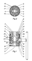
- the hammer drill chuck shown in FIGS. 1 and 2 has a tool holder 1 for the drilling tool (not shown) and a drilling spindle 2 Not shown drilling machine connected chuck body 3, which is axially broken through to the tool holder 1, so that during hammer drilling the impact of a striking member, not shown, located in the hollow drilling spindle can be transmitted directly to the end of the drilling tool held in the chuck via a striker, also not shown .
- drivers 4 which can be adjusted radially by rotating a coupling sleeve 6 such that they - as in the drawing - emerge radially from the tool holder 1 in pockets 7 of the coupling sleeve 6 or from the coupling sleeve 6 into the tool holder 1 are pushed in. In the latter case, they can engage in the longitudinal grooves provided in the shank of the drilling tool and thereby ensure its rotational driving even if the tool shank is only loosely axially displaceable between the chuck jaws 8.
- a jaw actuator 9 is rotatable on the chuck body 3 and is guided axially immovably by means of a spring ring indicated at 10.
- the jaw actuator 9 has radial bores which are open towards the tool holder 1 and which accommodate the chuck jaws 8 designed as cylindrical bolts.
- the chuck body 3 has on its front side facing the chuck jaws 8 a flat spiral thread 11 into which the chuck jaws 8 engage with corresponding flat spiral thread sections which are provided on the chuck jaw side facing the chuck body 3. In the drawing, the chuck jaws 8 are shown in their radially outermost position.
- the rotation of the jaw actuator 9 and thus the inward or outward radial adjustment of the clamping jaws 8 depending on the direction of rotation can be carried out with the aid of a chuck key 12 which can be attached to the chuck body 3 and which engages with a guide pin in a key receptacle 13 provided in the chuck body 3 and has a pinion 14, which engages with the chuck 13 attached to the drill chuck in the end teeth of a toothed ring 14 formed on the jaw actuator 9.
- an adjusting sleeve 21 is provided on the chuck body 3 in a coaxial guide seen that is in a fixed connection through a slot 15 in the chuck body 3 through a screw 16 with the coupling sleeve 6 and thus how this is adjustable between two operating positions.
- the jaw actuator 9 is freely rotatable and secured against rotation in the other, the securing case corresponding to the position of the coupling sleeve 6 in which the drivers 4 are adjusted radially into the tool holder 1.
- a locking lever 20 is provided, which is rotatably mounted on the chuck body 3 about a pivot axis 22 that is approximately radial to the chuck axis.
- the adjustment sleeve 21 which can be rotated between its two operating positions is provided with stops 23, 24, one of which comes into contact with the locking lever 20 in both directions of rotation and can thereby pivot the locking lever 20 when the adjustment sleeve 21 is turned.
- these stops 23, 24 hold the securing lever 20 in the two operating positions of the adjusting sleeve 21 either without connection or in positive and / or non-positive engagement with the jaw actuator 9.
- the safety lever 20 is designed as a two-armed (Fig. 1 to 5) or three-armed (Fig. 6 to 7) lever and comes with only a single lever arm 20.1 on the jaw actuator 9 to attack.
- This attack can result in a pure frictional connection with the jaw actuator 9, as in the embodiment according to FIG. 5, where the lever arm 20.1 acting on the jaw actuator 9 has a clamping surface 25 which is eccentric to the pivot axis 22 of the locking lever 20 for non-positive contact with the jaw actuator 9.
- the lever arm 20.1 acting on the jaw actuator 9 can also be provided with at least one locking tooth 26 and thus positively engage in the gaps of the ring gear 14 provided on the jaw actuator 9, as shown in FIGS. 1 to 4 and 6.1 to 7. Esp.
- the lever arm 20.1 acting on the jaw actuator 9 can be designed as a pawl which acts in one or the other direction of rotation of the ring gear 14, as shown in FIGS. 3 and 4 and 6.1 and 6.2.
- the tooth 20.1 is offset in the relevant direction of rotation with respect to the pivot axis 22 of the locking lever 20.
- the locking lever 20 leads to automatic locking if, when the locking lever 20 is engaged in the ring gear 14, the jaw actuator 9 with the ring gear 14 should be rotated in the direction of the arrow 27 shown in the figures relative to the chuck body 3.
- the lever arm 20.1 which acts on the jaw actuator 9 can act approximately counter to the direction of the engagement of its locking tooth 26 in the ring gear 14, that is essentially transversely to the lever arm axis, be elastically bendable, as is indicated in the example of FIG. 4 at 28 by a cross-sectional narrowing of the lever arm 20.1.
- the locking lever 20 on the stop 24 of the adjusting sleeve 21 in the form and / or non-positive connection with the jaw actuator 9 holding the lever arm 20.2 in the direction of the force exerted on it by the stop 24 is elastically bendable, as is particularly the case in the example of FIG.
- lever arm 20.2 is weakened again by a reduction in cross section at 29 and is therefore easier to bend transversely to its lever arm axis than the other two lever arms 20.1 and 20.3.
- an elastic resilience of the lever arms 20.1, 20.2 can serve to compensate for manufacturing-related tolerances and to ensure that the locking lever 20, which is on the one hand in positive and / or non-positive engagement on the jaw actuator 9, on the other hand, is actually assigned to it in the corresponding position of the adjusting sleeve 21 Stop 24 is present.
- the locking lever 20 is an essentially two-armed lever, then the locking lever 20 bears against the stops 23, 24 of the adjusting sleeve 21 essentially in one of its two directions of rotation, which are indicated in the figures by the arrows 30. So had in Fig. 3.1 the rotation of the adjusting sleeve 21 in the direction of arrow 30 relative to the chuck body 3, the locking lever 20 is moved via the stop 24 into the form-fit with the ring gear 14, and via this stop 24, the locking lever 20 is also in this position by the adjusting sleeve 21 held. Here, therefore, the adjusting sleeve 21 is in its operating position corresponding to the securing of the jaw actuator 9.
- FIG. 3.2 The other operating position of the adjusting sleeve, which releases the jaw actuator 9, is shown in FIG. 3.2.
- the rotation of the adjusting sleeve 21 relative to the chuck body 3 in the direction of arrow 30 has resulted in the locking lever 20 having been released from the positive fit on the ring gear 14 by abutment against the stop 23.
- the same relationships apply mutatis mutandis to the arrangements according to FIGS. 4 and 5. If, on the other hand, as in FIGS.
- this spring member is part of the locking device, namely the locking spring 18, which at the same time defines the operating positions of the adjusting sleeve 21 and the coupling sleeve 6 on the chuck body 3. Due to the locking process, the spring member 18 acts on the adjusting sleeve 21 in the direction of rotation in which it pivots the locking lever 20 into the position securing the jaw actuator 9 via its stop 24.
- the spring member can also be arranged directly between the securing lever 20 and the adjusting sleeve 21, as shown in FIG. 4.
- the spring member is designed as a spring arm 32 of the locking lever 20 which acts in the direction of the chuck axis and is subjected to bending in this direction, which exerts a torque on the locking lever 20 in the direction of the arrow 33 and thereby the locking lever 20 only more firmly in the positive fit on the ring gear 14 presses.
- the chuck key 12 can only be attached to the chuck body 3 when the adjusting sleeve 21 is not in its operating position which secures the jaw actuator 9 against rotation. Just then the adjusting sleeve 21 releases the key receptacle 13 through a window 36 in its wall. The chuck key 12 can therefore not be used to turn the jaw actuator 9 as long as it is locked against rotation by the locking lever 20.
Landscapes
- Engineering & Computer Science (AREA)
- Mechanical Engineering (AREA)
- Gripping On Spindles (AREA)
Applications Claiming Priority (2)
| Application Number | Priority Date | Filing Date | Title |
|---|---|---|---|
| DE3626474 | 1986-08-05 | ||
| DE19863626474 DE3626474A1 (de) | 1986-08-05 | 1986-08-05 | Bohrfutter, insbesondere hammerbohrfutter |
Publications (3)
| Publication Number | Publication Date |
|---|---|
| EP0255847A2 true EP0255847A2 (fr) | 1988-02-17 |
| EP0255847A3 EP0255847A3 (en) | 1989-04-26 |
| EP0255847B1 EP0255847B1 (fr) | 1991-05-08 |
Family
ID=6306722
Family Applications (1)
| Application Number | Title | Priority Date | Filing Date |
|---|---|---|---|
| EP86117773A Expired - Lifetime EP0255847B1 (fr) | 1986-08-05 | 1986-12-19 | Mandrin de perçage, en particulier mandrin de perçage à percussion |
Country Status (4)
| Country | Link |
|---|---|
| EP (1) | EP0255847B1 (fr) |
| JP (1) | JPH08323B2 (fr) |
| DE (2) | DE3626474A1 (fr) |
| ES (1) | ES2021587B3 (fr) |
Cited By (2)
| Publication number | Priority date | Publication date | Assignee | Title |
|---|---|---|---|---|
| EP0484379A4 (en) * | 1989-07-28 | 1993-09-01 | Gregory Fossella | Adjustable ratchet wrench |
| CN116213771A (zh) * | 2023-03-02 | 2023-06-06 | 中国铁建重工集团股份有限公司 | 一种柔性变径成型刀具 |
Families Citing this family (1)
| Publication number | Priority date | Publication date | Assignee | Title |
|---|---|---|---|---|
| DE4104131A1 (de) * | 1990-05-08 | 1991-11-14 | Bosch Gmbh Robert | Handbohrmaschine |
Family Cites Families (4)
| Publication number | Priority date | Publication date | Assignee | Title |
|---|---|---|---|---|
| DE3024996A1 (de) * | 1980-07-02 | 1982-01-28 | Günter Horst 7927 Sontheim Röhm | Bohrfutter |
| DE3338141A1 (de) * | 1983-10-20 | 1985-05-02 | Günter Horst 7927 Sontheim Röhm | Bohrfutter |
| DE3409494C2 (de) * | 1984-03-15 | 1987-03-05 | Licentia Patent-Verwaltungs-Gmbh, 6000 Frankfurt | Werkzeugaufnahme für eine elektropneumatisch arbeitende Hammerbohrmaschine |
| DE3438145C1 (de) * | 1984-10-18 | 1986-04-30 | Günter Horst 7927 Sontheim Röhm | Bohrfutter,insbesondere Schlagbohrfutter |
-
1986
- 1986-08-05 DE DE19863626474 patent/DE3626474A1/de not_active Withdrawn
- 1986-12-19 ES ES86117773T patent/ES2021587B3/es not_active Expired - Lifetime
- 1986-12-19 DE DE8686117773T patent/DE3679191D1/de not_active Expired - Lifetime
- 1986-12-19 EP EP86117773A patent/EP0255847B1/fr not_active Expired - Lifetime
-
1987
- 1987-05-21 JP JP62125657A patent/JPH08323B2/ja not_active Expired - Lifetime
Cited By (2)
| Publication number | Priority date | Publication date | Assignee | Title |
|---|---|---|---|---|
| EP0484379A4 (en) * | 1989-07-28 | 1993-09-01 | Gregory Fossella | Adjustable ratchet wrench |
| CN116213771A (zh) * | 2023-03-02 | 2023-06-06 | 中国铁建重工集团股份有限公司 | 一种柔性变径成型刀具 |
Also Published As
| Publication number | Publication date |
|---|---|
| EP0255847A3 (en) | 1989-04-26 |
| DE3679191D1 (de) | 1991-06-13 |
| DE3626474A1 (de) | 1988-02-11 |
| ES2021587B3 (es) | 1991-11-16 |
| EP0255847B1 (fr) | 1991-05-08 |
| JPH08323B2 (ja) | 1996-01-10 |
| JPS6339705A (ja) | 1988-02-20 |
Similar Documents
| Publication | Publication Date | Title |
|---|---|---|
| DE69526674T2 (de) | Eintreibewerkzeug-einsatz für befestigungsmittel | |
| EP0530431B1 (fr) | Mandrin de perçage | |
| DE4238464C1 (de) | Selbstspannendes Bohrfutter | |
| EP0622143B1 (fr) | Mandrin de perceuse | |
| DE4438991B4 (de) | Bohrfutter | |
| DE4445858B4 (de) | Bohrvorrichtung | |
| EP0680798A1 (fr) | Mandrin sans clef | |
| DE3405511C1 (de) | Spannfutter,insbes.Bohrfutter | |
| EP0017748A1 (fr) | Porte-forêt avec plateau-poussoir | |
| EP0302992A1 (fr) | Mandrin à reserrage | |
| EP0570675A1 (fr) | Pince pour la préhension et le maintien de tissus | |
| CH663918A5 (de) | Schlagbohreinrichtung. | |
| WO2014131522A1 (fr) | Poignée de commande | |
| DE102006048563B4 (de) | Schlagschraubergerät mit Stiftschlagwerk und Drehmomentbegrenzung | |
| EP0716896A1 (fr) | Dispositif de perçage | |
| EP0195193B1 (fr) | Mandrin pour forage rotatif ou rotatif avec percussion | |
| DE2916559C2 (de) | Lenkschloß | |
| EP1946892B1 (fr) | Clé à chocs | |
| EP0255847B1 (fr) | Mandrin de perçage, en particulier mandrin de perçage à percussion | |
| DE4238465C1 (de) | Bohrfutter | |
| EP0824996A1 (fr) | Pince à ouverture variable | |
| EP0180831B1 (fr) | Pince à tuyaux | |
| EP4532141B1 (fr) | Outil de vissage équipé d'un mécanisme de blocage de roue libre à sens réversible | |
| EP4505088A1 (fr) | Arrangement d'articulation de connexion | |
| DE102022114689A1 (de) | Schraubwerkzeug mit Drehmomentbegrenzungseinrichtung |
Legal Events
| Date | Code | Title | Description |
|---|---|---|---|
| PUAI | Public reference made under article 153(3) epc to a published international application that has entered the european phase |
Free format text: ORIGINAL CODE: 0009012 |
|
| AK | Designated contracting states |
Kind code of ref document: A2 Designated state(s): DE ES FR GB IT NL SE |
|
| PUAL | Search report despatched |
Free format text: ORIGINAL CODE: 0009013 |
|
| AK | Designated contracting states |
Kind code of ref document: A3 Designated state(s): DE ES FR GB IT NL SE |
|
| 17P | Request for examination filed |
Effective date: 19890317 |
|
| 17Q | First examination report despatched |
Effective date: 19900827 |
|
| GRAA | (expected) grant |
Free format text: ORIGINAL CODE: 0009210 |
|
| AK | Designated contracting states |
Kind code of ref document: B1 Designated state(s): DE ES FR GB IT NL SE |
|
| REF | Corresponds to: |
Ref document number: 3679191 Country of ref document: DE Date of ref document: 19910613 |
|
| ITF | It: translation for a ep patent filed | ||
| ET | Fr: translation filed | ||
| GBT | Gb: translation of ep patent filed (gb section 77(6)(a)/1977) | ||
| PLBE | No opposition filed within time limit |
Free format text: ORIGINAL CODE: 0009261 |
|
| STAA | Information on the status of an ep patent application or granted ep patent |
Free format text: STATUS: NO OPPOSITION FILED WITHIN TIME LIMIT |
|
| 26N | No opposition filed | ||
| PGFP | Annual fee paid to national office [announced via postgrant information from national office to epo] |
Ref country code: GB Payment date: 19921005 Year of fee payment: 7 |
|
| PGFP | Annual fee paid to national office [announced via postgrant information from national office to epo] |
Ref country code: FR Payment date: 19921007 Year of fee payment: 7 |
|
| PGFP | Annual fee paid to national office [announced via postgrant information from national office to epo] |
Ref country code: SE Payment date: 19921109 Year of fee payment: 7 |
|
| PGFP | Annual fee paid to national office [announced via postgrant information from national office to epo] |
Ref country code: ES Payment date: 19921203 Year of fee payment: 7 |
|
| PGFP | Annual fee paid to national office [announced via postgrant information from national office to epo] |
Ref country code: NL Payment date: 19921231 Year of fee payment: 7 |
|
| PG25 | Lapsed in a contracting state [announced via postgrant information from national office to epo] |
Ref country code: GB Effective date: 19931219 |
|
| PG25 | Lapsed in a contracting state [announced via postgrant information from national office to epo] |
Ref country code: SE Effective date: 19931220 Ref country code: ES Free format text: LAPSE BECAUSE OF EXPIRATION OF PROTECTION Effective date: 19931220 |
|
| PG25 | Lapsed in a contracting state [announced via postgrant information from national office to epo] |
Ref country code: NL Effective date: 19940701 |
|
| NLV4 | Nl: lapsed or anulled due to non-payment of the annual fee | ||
| GBPC | Gb: european patent ceased through non-payment of renewal fee |
Effective date: 19931219 |
|
| PG25 | Lapsed in a contracting state [announced via postgrant information from national office to epo] |
Ref country code: FR Effective date: 19940831 |
|
| REG | Reference to a national code |
Ref country code: FR Ref legal event code: ST |
|
| EUG | Se: european patent has lapsed |
Ref document number: 86117773.1 Effective date: 19940710 |
|
| PGFP | Annual fee paid to national office [announced via postgrant information from national office to epo] |
Ref country code: DE Payment date: 20000126 Year of fee payment: 14 |
|
| REG | Reference to a national code |
Ref country code: ES Ref legal event code: FD2A Effective date: 20010201 |
|
| PG25 | Lapsed in a contracting state [announced via postgrant information from national office to epo] |
Ref country code: DE Free format text: LAPSE BECAUSE OF NON-PAYMENT OF DUE FEES Effective date: 20011002 |
|
| PG25 | Lapsed in a contracting state [announced via postgrant information from national office to epo] |
Ref country code: IT Free format text: LAPSE BECAUSE OF NON-PAYMENT OF DUE FEES Effective date: 20051219 |