EP0255879A2 - Charnière de porte de véhicule avec un arrêt de porte - Google Patents
Charnière de porte de véhicule avec un arrêt de porte Download PDFInfo
- Publication number
- EP0255879A2 EP0255879A2 EP19870109979 EP87109979A EP0255879A2 EP 0255879 A2 EP0255879 A2 EP 0255879A2 EP 19870109979 EP19870109979 EP 19870109979 EP 87109979 A EP87109979 A EP 87109979A EP 0255879 A2 EP0255879 A2 EP 0255879A2
- Authority
- EP
- European Patent Office
- Prior art keywords
- door
- hinge
- eye
- profile
- hinge according
- Prior art date
- Legal status (The legal status is an assumption and is not a legal conclusion. Google has not performed a legal analysis and makes no representation as to the accuracy of the status listed.)
- Granted
Links
Images
Classifications
-
- E—FIXED CONSTRUCTIONS
- E05—LOCKS; KEYS; WINDOW OR DOOR FITTINGS; SAFES
- E05D—HINGES OR SUSPENSION DEVICES FOR DOORS, WINDOWS OR WINGS
- E05D11/00—Additional features or accessories of hinges
- E05D11/10—Devices for preventing movement between relatively-movable hinge parts
- E05D11/1028—Devices for preventing movement between relatively-movable hinge parts for maintaining the hinge in two or more positions, e.g. intermediate or fully open
- E05D11/105—Devices for preventing movement between relatively-movable hinge parts for maintaining the hinge in two or more positions, e.g. intermediate or fully open the maintaining means acting perpendicularly to the pivot axis
- E05D11/1057—Devices for preventing movement between relatively-movable hinge parts for maintaining the hinge in two or more positions, e.g. intermediate or fully open the maintaining means acting perpendicularly to the pivot axis specially adapted for vehicles
-
- E—FIXED CONSTRUCTIONS
- E05—LOCKS; KEYS; WINDOW OR DOOR FITTINGS; SAFES
- E05D—HINGES OR SUSPENSION DEVICES FOR DOORS, WINDOWS OR WINGS
- E05D11/00—Additional features or accessories of hinges
- E05D11/10—Devices for preventing movement between relatively-movable hinge parts
- E05D11/1028—Devices for preventing movement between relatively-movable hinge parts for maintaining the hinge in two or more positions, e.g. intermediate or fully open
- E05D2011/1035—Devices for preventing movement between relatively-movable hinge parts for maintaining the hinge in two or more positions, e.g. intermediate or fully open with circumferential and evenly distributed detents around the pivot-axis
-
- E—FIXED CONSTRUCTIONS
- E05—LOCKS; KEYS; WINDOW OR DOOR FITTINGS; SAFES
- E05Y—INDEXING SCHEME ASSOCIATED WITH SUBCLASSES E05D AND E05F, RELATING TO CONSTRUCTION ELEMENTS, ELECTRIC CONTROL, POWER SUPPLY, POWER SIGNAL OR TRANSMISSION, USER INTERFACES, MOUNTING OR COUPLING, DETAILS, ACCESSORIES, AUXILIARY OPERATIONS NOT OTHERWISE PROVIDED FOR, APPLICATION THEREOF
- E05Y2900/00—Application of doors, windows, wings or fittings thereof
- E05Y2900/50—Application of doors, windows, wings or fittings thereof for vehicles
- E05Y2900/53—Type of wing
- E05Y2900/531—Doors
Definitions
- the invention relates to a door hinge for a vehicle door, with a post part, a door part, a hinge pin pivotally connecting both parts, and with a door retainer for temporarily locking the door in at least one opening position, in which a profile and the other on the hinge part for locking the door Hinge part a locking element are attached, which move relative to each other with the hinge movement with elastic contact, and the hinge pin is anchored in at least one eye of one hinge part rotatably or pluggable and rotatably anchored and pivotally mounted in the eye of the other hinge part in at least one multi-layer bearing bush is.
- Door hinges of this type are used, in particular, on car doors, an intermediate locking device with an opening angle of approximately 45 ° and a final locking device with an opening angle of 80 ° to 85 ° being generally provided.
- a torsion spring bent like a clasp is used as the locking element and, with the help of small rolling elements, dips into corresponding recesses along the profiling in the locking positions.
- the clasp-like torsion spring takes up a relatively large amount of space, since a relatively long clasp must be used to bring about a suitable spring force.
- the required construction volume reaches such an extent that the torsion spring has to be accommodated inside the door body, since the limited space outside the door body as a rule is not sufficient up to the door jamb. Sealing the door interior is correspondingly difficult since a relatively large, irregular opening must be sealed against the ingress of water and moisture.
- the invention proposes that the hinge pin is provided with at least one elongated locking element parallel to its longitudinal axis, and that the eye bearing the bearing bush is provided with the profiling on the inner surface facing the hinge pin.
- the entire door lock is housed within the one eye, in which the relative movement when the hinge is pivoted, that is to say when the door is opened and closed ordered vehicle door takes place.
- the hinge according to the invention can hardly be distinguished from a conventional, simple hinge without a door lock; at most, the somewhat stronger hinge pin and the larger diameter of one eye of one hinge part catches the eye.
- the door arrester Due to the accommodation of the door arrester in a confined space, it can be accommodated in the space between the door and the jamb in almost all common vehicles, so that the previous type of hinge attachment can be retained and the hinge required until then can be omitted.
- the elastic contact of the latching elements on the profiling is brought about by an elastic deformation of the corresponding eye.
- the eye is relatively thin-walled, so that it can not only expand elastically in the form of a ring, but can also stretch between the individual locking elements in the areas of the highest stress, so that in addition to the expansion, an elastic deformation due to a temporary polygon shape is achievable.
- the resulting elastic deformation can be easily controlled.
- the door hinge according to the invention depends on a particularly firm fit of the hinge pin in the one hinge part in which the hinge pin is anchored anyway.
- the hinge pin is stepped, so that in the case of a hinge in which one hinge part encompasses the other on both sides, anchors can be provided in the two outer hinge eyes.
- a polygonal profile for example a square or a hexagon, can then be attached in particular to the thin section of the stepped hinge pin, which in any case brings about the desired solid, non-rotatable anchoring.
- Such a polygonal profile anchoring is also recommended in the case of an embodiment of a pluggable hinge, in which, after the adjustment, the hinge can be dismantled and re-attached as often as desired without losing the basic adjustment.
- Corresponding projections made of the base material can be formed on the bolts as locking elements; in deviation from this, steel needles can be partially embedded in the base material of the hinge pin, which are available as purchased parts from the area of the needle bearing industry. Finally, elastic or elastically supported strips can be accommodated in corresponding longitudinal grooves of the bolt, which then interact with a rigid eye that does not require a resilient widening, since the elasticity is obtained from the strips or from the support of the strips.
- the profiling is stamped into a profile sheet, and that an elastomer layer is arranged between the profile sheet and the inner surface of the eye, in particular is injected. In this way, all metal parts are not subject to deformation, apart from the slight bending deformation of the profile sheets. The required elasticity is provided by the elastomer layer, which can be adjusted in almost any hardness and wear resistance.
- the profile sheet In the area of the end stop, it is expedient to support the profile sheet directly on the inner surface of the associated eye, which can be brought about by separate feet or by a correspondingly bent edge region of the profile sheet. In this way, the effect of the elastomer layer is canceled at this point, that is, a particular hardening to form the end stop is achieved.
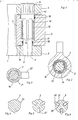
- the hinge shown is of a type in which the post part 1 is provided with outer eyes 4 and 5 which engage laterally around a middle eye 7 on the door part 2. Through the eyes 4, 5 and 7, a through hole 6 is present in the aligned position, but is stepped; the opening in the upper eye 4 is larger than that in the lower eye 5.
- the actual pivotable mounting between the two hinge parts 1 and 2 takes place between the middle eye 7 on the one hand and the hinge pin 3 on the other hand with the aid of two bearing sleeves 10 which are provided with a corresponding collar for the axial fixing.
- the hinge pin 3 has corrugations 11 at its outer ends, of which only those at the upper end are shown in FIG. 1. Since the hinge pin 3 is designed as a stepped pin, the rotationally fixed anchoring in both the upper eye 4 and in the lower eye 5 is particularly simple. Deviating from corrugation at the lower end, a polygonal profile can also be present at this point, for example a square or a hexagon, which plunges into a correspondingly shaped eye 5.
- the actual door lock is accommodated between the bearing bushes 10, but in the broader sense this also includes the rotationally fixed anchoring of the hinge pin 3 within the post part 1.
- the hinge pin 3 is equipped in this area with three steel needles 14, which serve as locking elements and are partially embedded in three longitudinal grooves evenly distributed around the circumference (FIG. 2). They interact with three profile sheets 15, each of which is supported on an inner surface 17 of the middle eye 7 via an elastomer layer 16. In the three profile sheets, the same profile is stamped in each case, which can be seen particularly well from FIG. 2.
- Each profile sheet 15 is folded on one side area so that the one free longitudinal edge stands on the inner surface 17 of the middle eye 7. At this point, the elasticity is virtually eliminated due to the supporting elastomer layer 16.
- the immediately adjacent indentation for receiving the corresponding latching element 14 is virtually unyielding on the corresponding side and forms the locking device that coincides with the end position locking of the door.
- the adjacent indentation within each profile sheet 15 causes an intermediate locking, for example at a door opening angle of 45 °.
- FIG. 2 shows the closed position, in which the latching effect is approximately neutral.
- the middle eye 21 has a substantially thinner wall and the profile is stamped directly into the inner surface.
- the profiles are less pronounced because less spring travel is available.
- the ring-shaped middle eye 21 is namely elastically deformed, so this deformation provides the required elasticity between the three steel needles 14 and the profiling.
- the middle eye 21 When a door carried by this type of hinge is opened and closed, the middle eye 21 widens elastically, which also leads to stretching in the areas between two steel needles 14. Roughly speaking, there is a triangular deformation in particular at very high profile points, which rotates with the steel needles 14.
- care is taken that the highest profile points of one of the three profile sections are placed in the area of the connecting plate 22, since in this area anyway the elastic deformation is lowest. In this way, a particularly uniform loading of the thin-walled middle eye 21 is achieved.
- latching elements are formed as latching projections 26 from the base material, which can be used together with the exemplary embodiments according to FIGS. 1 and 2 and according to FIG. 3.
- latching strips 27 made of an elastomer material are used in longitudinal grooves, so that the elastomer layer 16 in the embodiment according to FIGS. 1 and 2 or the elastic expansion in the embodiment according to FIG. 3 is not required. Rather, the locking strips 27 elastically dodge the profile tips of the profiling within the inner surface of the middle eye.
- metal caps which can optionally be pivotally held on the hinge pin 3 with lateral flags.
- strip-like protective caps can be vulcanized onto the elastomer strips 27.
- composite latching strips 31 available, which in turn carry steel needles 32 on their end face.
- the rigid locking tabs 31 are elastically supported in the hinge pin 3 via springs 33, wherein the springs 33 can be distributed over the entire length; For example, eight relatively hard small coil springs are used per assembled locking bar 31.
- the elastomer layer 16 in the exemplary embodiment according to FIGS. 1 and 2 is not only subjected to pressure in the radial direction, but is also very strongly subjected to shear, since the steel needles 14 attempt to turn the profile eyes 15 when the middle eye 7 rotates around the fixed hinge pin 3 to take with you. For this reason, it may be expedient to design the inner surface 17 of the middle eye 7 over a large area, that is to provide it with corrugation for better adhesion.
- the edges of the profiled sheets resting on the inner surface can be embedded in corresponding grooves (not shown), so that an anti-rotation device is already present at this point.
Landscapes
- Engineering & Computer Science (AREA)
- Mechanical Engineering (AREA)
- Hinge Accessories (AREA)
- Hinges (AREA)
- Body Structure For Vehicles (AREA)
Applications Claiming Priority (2)
| Application Number | Priority Date | Filing Date | Title |
|---|---|---|---|
| DE8621214U | 1986-08-07 | ||
| DE19868621214 DE8621214U1 (de) | 1986-08-07 | 1986-08-07 | Türscharnier für eine Fahrzeugtür mit einem Türfeststeller |
Publications (3)
| Publication Number | Publication Date |
|---|---|
| EP0255879A2 true EP0255879A2 (fr) | 1988-02-17 |
| EP0255879A3 EP0255879A3 (en) | 1988-05-04 |
| EP0255879B1 EP0255879B1 (fr) | 1991-09-04 |
Family
ID=6797243
Family Applications (1)
| Application Number | Title | Priority Date | Filing Date |
|---|---|---|---|
| EP87109979A Expired - Lifetime EP0255879B1 (fr) | 1986-08-07 | 1987-07-10 | Charnière de porte de véhicule avec un arrêt de porte |
Country Status (3)
| Country | Link |
|---|---|
| EP (1) | EP0255879B1 (fr) |
| DE (2) | DE8621214U1 (fr) |
| ES (1) | ES2026156T3 (fr) |
Cited By (16)
| Publication number | Priority date | Publication date | Assignee | Title |
|---|---|---|---|---|
| WO1990015728A1 (fr) * | 1989-06-21 | 1990-12-27 | Mgi Coutier (S.A.) | Dispositif d'arret de porte, notamment de porte de vehicule |
| FR2658556A1 (fr) * | 1990-02-20 | 1991-08-23 | Comaci | Charniere a arret de porte integre pour vehicules ou autres ouvrants. |
| EP0443919A1 (fr) * | 1990-02-20 | 1991-08-28 | COMACI Société Anonyme | Charnière à arrêt de porte intégré pour véhicules ou autres ouvrants |
| FR2660008A1 (fr) * | 1990-03-21 | 1991-09-27 | Pezin Jacques | Dispositif d'arret de porte integre a l'interieur d'une charniere. |
| EP0519141A1 (fr) * | 1991-06-21 | 1992-12-23 | COMACI Société Anonyme | Charnier à arrêt de porte intégré pour véhicules ou autres ouvrants |
| WO1993003248A1 (fr) * | 1991-08-09 | 1993-02-18 | Stefan Nazarewski | Systeme d'arret, notamment pour des charnieres de portieres de vehicules automobiles |
| DE4300134A1 (fr) * | 1992-01-13 | 1993-07-15 | Southco | |
| DE4406824A1 (de) * | 1994-03-02 | 1995-09-07 | Hans Kuehl | Scharnier mit Schwenkhemmung |
| GB2342120A (en) * | 1996-07-15 | 2000-04-05 | Southco | Door hinge with elastomer spring |
| FR2812700A1 (fr) * | 2000-08-04 | 2002-02-08 | Itw De France | Dispositif ralentisseur de rotation a prise directe |
| US6601268B2 (en) * | 2000-11-24 | 2003-08-05 | Hyundai Motor Company | Door hinge cum door checker of vehicles |
| US6629337B2 (en) * | 2001-11-28 | 2003-10-07 | Edscha Roof Systems Inc. | Double-pivot resistance hinge for motor vehicle door |
| EP2460965A3 (fr) * | 2010-12-02 | 2012-08-01 | Sedus Stoll AG | Palier freiné et mobilier, notamment table pliante |
| US8959717B2 (en) | 2012-03-12 | 2015-02-24 | Reell Precision Manufacturing Corporation | Circumferential strain rotary detent |
| WO2021052874A1 (fr) | 2019-09-20 | 2021-03-25 | Koninklijke Philips N.V. | Mécanisme d'amortissement, dispositif de bobine rf et appareil d'irm |
| EP3832334A1 (fr) * | 2019-12-02 | 2021-06-09 | Koninklijke Philips N.V. | Mécanisme d'amortissement, dispositif de bobine rf et appareil d'irm |
Families Citing this family (11)
| Publication number | Priority date | Publication date | Assignee | Title |
|---|---|---|---|---|
| JP2739164B2 (ja) * | 1994-12-27 | 1998-04-08 | トックベアリング株式会社 | 回転ダンパにおける自立機構 |
| DE29605809U1 (de) * | 1996-03-28 | 1997-07-24 | Mayer & Co., Salzburg | Scherenlager für Flügel |
| DE19625557A1 (de) * | 1996-06-26 | 1998-01-08 | Hans Dipl Ing Kuehl | Scharnier für Türen mit Schwenkhemmung |
| US5765263A (en) * | 1996-07-15 | 1998-06-16 | Southco, Inc. | Door positioning hinge |
| DE19755547A1 (de) * | 1997-12-13 | 1999-06-17 | Schaeffler Waelzlager Ohg | Lagerung für eine Fahrzeugtür mit integriertem Türfeststeller |
| JP2002511545A (ja) * | 1998-04-09 | 2002-04-16 | エー・デー・シャルベヒテル・ゲゼルシャフト・ミット・ベシュレンクテル・ハフツング | ドアヒンジと構造的に組合されるドアストップ |
| DE19907455A1 (de) * | 1999-02-22 | 2000-08-31 | Scharwaechter Ed Gmbh | Kraftwagentürbremse mit Haltefunktion |
| CA2277114C (fr) * | 1999-07-07 | 2004-06-01 | Multimatic Inc. | Charniere de controle de portiere integree pour automobiles |
| FR2835581B1 (fr) * | 2002-02-04 | 2005-07-01 | Itw Fastex France | Dispositif ralentisseur de rotation et utilisation de celui-ci |
| DE10343587B4 (de) | 2003-09-18 | 2005-09-01 | Ise Innomotive Systems Europe Gmbh | Türscharnier mit Feststeller für Kraftfahrzeugtüren |
| FR3012505B1 (fr) * | 2013-10-24 | 2017-01-13 | Pinet Ind | Charniere ou equivalent a cliquet |
Family Cites Families (7)
| Publication number | Priority date | Publication date | Assignee | Title |
|---|---|---|---|---|
| CH378186A (de) * | 1960-03-08 | 1964-05-31 | Otto Jordi Gottfried | Fischband mit Drehbremse |
| CH461984A (fr) * | 1968-03-06 | 1968-08-31 | Paulian Benoit | Gond |
| DE2016516B2 (de) * | 1970-04-07 | 1975-11-06 | Elster Ag Mess- Und Regeltechnik, 6500 Mainz | Feststellvorrichtung für Türen |
| GB1391095A (en) * | 1972-08-12 | 1975-04-16 | Ihw Eng Ltd | Door hinge |
| DE3401245A1 (de) * | 1984-01-16 | 1985-07-18 | Lunke & Sohn Gmbh, 5810 Witten | Tuerscharnier fuer ein kraftfahrzeug |
| DE8401062U1 (de) * | 1984-01-16 | 1987-03-26 | Lunke & Sohn Gmbh, 5810 Witten | Demontierbares Kfz-Türscharnier |
| DE3401252A1 (de) * | 1984-01-16 | 1985-07-18 | Lunke & Sohn Gmbh, 5810 Witten | Demontierbares kfz-tuerscharnier |
-
1986
- 1986-08-07 DE DE19868621214 patent/DE8621214U1/de not_active Expired
-
1987
- 1987-07-10 EP EP87109979A patent/EP0255879B1/fr not_active Expired - Lifetime
- 1987-07-10 DE DE8787109979T patent/DE3772663D1/de not_active Expired - Lifetime
- 1987-07-10 ES ES87109979T patent/ES2026156T3/es not_active Expired - Lifetime
Cited By (22)
| Publication number | Priority date | Publication date | Assignee | Title |
|---|---|---|---|---|
| WO1990015728A1 (fr) * | 1989-06-21 | 1990-12-27 | Mgi Coutier (S.A.) | Dispositif d'arret de porte, notamment de porte de vehicule |
| FR2648761A1 (fr) * | 1989-06-21 | 1990-12-28 | Coutier Moulage Gen Ind | Dispositif d'arret de porte, notamment de porte de vehicule |
| FR2658556A1 (fr) * | 1990-02-20 | 1991-08-23 | Comaci | Charniere a arret de porte integre pour vehicules ou autres ouvrants. |
| EP0443919A1 (fr) * | 1990-02-20 | 1991-08-28 | COMACI Société Anonyme | Charnière à arrêt de porte intégré pour véhicules ou autres ouvrants |
| FR2661940A2 (fr) * | 1990-02-20 | 1991-11-15 | Comaci | Charniere a arret de porte integre pour portes de vehicules ou autres ouvrants. |
| FR2660008A1 (fr) * | 1990-03-21 | 1991-09-27 | Pezin Jacques | Dispositif d'arret de porte integre a l'interieur d'une charniere. |
| EP0519141A1 (fr) * | 1991-06-21 | 1992-12-23 | COMACI Société Anonyme | Charnier à arrêt de porte intégré pour véhicules ou autres ouvrants |
| WO1993003248A1 (fr) * | 1991-08-09 | 1993-02-18 | Stefan Nazarewski | Systeme d'arret, notamment pour des charnieres de portieres de vehicules automobiles |
| DE4300134B4 (de) * | 1992-01-13 | 2007-05-03 | Southco, Inc. | Haltescharnier |
| DE4300134A1 (fr) * | 1992-01-13 | 1993-07-15 | Southco | |
| DE4406824A1 (de) * | 1994-03-02 | 1995-09-07 | Hans Kuehl | Scharnier mit Schwenkhemmung |
| GB2342120A (en) * | 1996-07-15 | 2000-04-05 | Southco | Door hinge with elastomer spring |
| GB2342120B (en) * | 1996-07-15 | 2001-02-28 | Southco | Door positioning hinge |
| FR2812700A1 (fr) * | 2000-08-04 | 2002-02-08 | Itw De France | Dispositif ralentisseur de rotation a prise directe |
| US6601268B2 (en) * | 2000-11-24 | 2003-08-05 | Hyundai Motor Company | Door hinge cum door checker of vehicles |
| US6629337B2 (en) * | 2001-11-28 | 2003-10-07 | Edscha Roof Systems Inc. | Double-pivot resistance hinge for motor vehicle door |
| EP2460965A3 (fr) * | 2010-12-02 | 2012-08-01 | Sedus Stoll AG | Palier freiné et mobilier, notamment table pliante |
| US8959717B2 (en) | 2012-03-12 | 2015-02-24 | Reell Precision Manufacturing Corporation | Circumferential strain rotary detent |
| WO2021052874A1 (fr) | 2019-09-20 | 2021-03-25 | Koninklijke Philips N.V. | Mécanisme d'amortissement, dispositif de bobine rf et appareil d'irm |
| CN114424078A (zh) * | 2019-09-20 | 2022-04-29 | 皇家飞利浦有限公司 | 阻尼机构、rf线圈装置和mri设备 |
| US11675033B2 (en) | 2019-09-20 | 2023-06-13 | Koninklijke Philips N.V. | Damping mechanism, RF coil device and MRI apparatus |
| EP3832334A1 (fr) * | 2019-12-02 | 2021-06-09 | Koninklijke Philips N.V. | Mécanisme d'amortissement, dispositif de bobine rf et appareil d'irm |
Also Published As
| Publication number | Publication date |
|---|---|
| DE8621214U1 (de) | 1987-12-03 |
| ES2026156T3 (es) | 1992-04-16 |
| EP0255879A3 (en) | 1988-05-04 |
| EP0255879B1 (fr) | 1991-09-04 |
| DE3772663D1 (de) | 1991-10-10 |
Similar Documents
| Publication | Publication Date | Title |
|---|---|---|
| EP0255879B1 (fr) | Charnière de porte de véhicule avec un arrêt de porte | |
| EP0266490B1 (fr) | Charnière pour porte de véhicule | |
| EP2414180B1 (fr) | Articulation elastomere | |
| EP0807738B1 (fr) | Charnière de porte décrochable à l'arrêtoir de porte intégré | |
| DE2030533A1 (de) | Zusammengesetzte Blattfeder | |
| DE4136704A1 (de) | Abdichtungsvorrichtung zum einbau in lager, insbesondere radiallager | |
| DE3943407A1 (de) | Tuerfeststeller fuer kraftwagentueren | |
| DE69909359T2 (de) | Distanzhülse | |
| DE3401252A1 (de) | Demontierbares kfz-tuerscharnier | |
| DE69110461T2 (de) | Türhaltestange für Reibungstürfeststeller und Türfeststeller mit solcher Türhaltestange. | |
| EP0656271B1 (fr) | Pivot, en particulier pour un guide d'essieu d'un véhicule à moteur | |
| DE7937064U1 (de) | Kugelgelenk | |
| DE3902879A1 (de) | Federabstuetzung fuer einen kraftwagentuerfeststeller | |
| DE8916127U1 (de) | Vorrichtung zur federnden Einspannung von Traversen einer Fahrbahnüberbrückungskonstruktion | |
| CH644562A5 (de) | Verriegelungseinrichtung an einem behaelter. | |
| DE1915751C3 (de) | Schwenklagerung für Türhaltebänder von Türfeststellern für Kraftwagentüren | |
| DE9017065U1 (de) | Kraftfahrzeugtür-Scharnier | |
| DE69011890T2 (de) | Feder mit zwei stabilen Gleichgewichtszuständen. | |
| DE29617518U1 (de) | Türfeststeller | |
| DE2449661A1 (de) | Tuerfeststeller, insbesondere fuer kraftwagentueren | |
| DE9202108U1 (de) | Vorrichtung zum Feststellen einer Tür, insbesondere einer Kraftfahrzeugtür | |
| DE19810365C2 (de) | Scharnier | |
| DE202009015948U1 (de) | Türband | |
| DE3440139C2 (de) | Abgeschirmte Schraubenzugfeder für Tore oder dergleichen | |
| DE102006025215B4 (de) | Kraftfahrzeugscharnier für Türen und Klappen |
Legal Events
| Date | Code | Title | Description |
|---|---|---|---|
| PUAI | Public reference made under article 153(3) epc to a published international application that has entered the european phase |
Free format text: ORIGINAL CODE: 0009012 |
|
| AK | Designated contracting states |
Kind code of ref document: A2 Designated state(s): DE ES FR GB IT |
|
| PUAL | Search report despatched |
Free format text: ORIGINAL CODE: 0009013 |
|
| AK | Designated contracting states |
Kind code of ref document: A3 Designated state(s): DE ES FR GB IT |
|
| 17P | Request for examination filed |
Effective date: 19880929 |
|
| 17Q | First examination report despatched |
Effective date: 19900806 |
|
| RAP3 | Party data changed (applicant data changed or rights of an application transferred) |
Owner name: LUNKE & SOHN AKTIENGESELLSCHAFT |
|
| ITF | It: translation for a ep patent filed | ||
| GRAA | (expected) grant |
Free format text: ORIGINAL CODE: 0009210 |
|
| AK | Designated contracting states |
Kind code of ref document: B1 Designated state(s): DE ES FR GB IT |
|
| REF | Corresponds to: |
Ref document number: 3772663 Country of ref document: DE Date of ref document: 19911010 |
|
| ET | Fr: translation filed | ||
| GBT | Gb: translation of ep patent filed (gb section 77(6)(a)/1977) | ||
| REG | Reference to a national code |
Ref country code: ES Ref legal event code: FG2A Ref document number: 2026156 Country of ref document: ES Kind code of ref document: T3 |
|
| PLBE | No opposition filed within time limit |
Free format text: ORIGINAL CODE: 0009261 |
|
| STAA | Information on the status of an ep patent application or granted ep patent |
Free format text: STATUS: NO OPPOSITION FILED WITHIN TIME LIMIT |
|
| PG25 | Lapsed in a contracting state [announced via postgrant information from national office to epo] |
Ref country code: GB Effective date: 19920710 |
|
| PG25 | Lapsed in a contracting state [announced via postgrant information from national office to epo] |
Ref country code: ES Free format text: LAPSE BECAUSE OF THE APPLICANT RENOUNCES Effective date: 19920711 |
|
| 26N | No opposition filed | ||
| GBPC | Gb: european patent ceased through non-payment of renewal fee |
Effective date: 19920710 |
|
| PG25 | Lapsed in a contracting state [announced via postgrant information from national office to epo] |
Ref country code: FR Effective date: 19930331 |
|
| PG25 | Lapsed in a contracting state [announced via postgrant information from national office to epo] |
Ref country code: DE Effective date: 19930401 |
|
| REG | Reference to a national code |
Ref country code: FR Ref legal event code: ST |
|
| REG | Reference to a national code |
Ref country code: ES Ref legal event code: FD2A Effective date: 19991007 |
|
| PG25 | Lapsed in a contracting state [announced via postgrant information from national office to epo] |
Ref country code: IT Free format text: LAPSE BECAUSE OF NON-PAYMENT OF DUE FEES;WARNING: LAPSES OF ITALIAN PATENTS WITH EFFECTIVE DATE BEFORE 2007 MAY HAVE OCCURRED AT ANY TIME BEFORE 2007. THE CORRECT EFFECTIVE DATE MAY BE DIFFERENT FROM THE ONE RECORDED. Effective date: 20050710 |