EP0807738B1 - Charnière de porte décrochable à l'arrêtoir de porte intégré - Google Patents
Charnière de porte décrochable à l'arrêtoir de porte intégré Download PDFInfo
- Publication number
- EP0807738B1 EP0807738B1 EP97106759A EP97106759A EP0807738B1 EP 0807738 B1 EP0807738 B1 EP 0807738B1 EP 97106759 A EP97106759 A EP 97106759A EP 97106759 A EP97106759 A EP 97106759A EP 0807738 B1 EP0807738 B1 EP 0807738B1
- Authority
- EP
- European Patent Office
- Prior art keywords
- hinge
- motor
- vehicle door
- braking
- door hinge
- Prior art date
- Legal status (The legal status is an assumption and is not a legal conclusion. Google has not performed a legal analysis and makes no representation as to the accuracy of the status listed.)
- Expired - Lifetime
Links
- 238000005096 rolling process Methods 0.000 claims description 8
- 230000015572 biosynthetic process Effects 0.000 claims description 2
- 230000001681 protective effect Effects 0.000 claims description 2
- 238000005755 formation reaction Methods 0.000 claims 1
- 238000009434 installation Methods 0.000 description 5
- 230000000295 complement effect Effects 0.000 description 2
- 238000004519 manufacturing process Methods 0.000 description 2
- 230000002411 adverse Effects 0.000 description 1
- 238000010276 construction Methods 0.000 description 1
- 230000008878 coupling Effects 0.000 description 1
- 238000010168 coupling process Methods 0.000 description 1
- 238000005859 coupling reaction Methods 0.000 description 1
- 239000000428 dust Substances 0.000 description 1
- 230000000694 effects Effects 0.000 description 1
- 239000000463 material Substances 0.000 description 1
- 230000002093 peripheral effect Effects 0.000 description 1
Images
Classifications
-
- E—FIXED CONSTRUCTIONS
- E05—LOCKS; KEYS; WINDOW OR DOOR FITTINGS; SAFES
- E05D—HINGES OR SUSPENSION DEVICES FOR DOORS, WINDOWS OR WINGS
- E05D11/00—Additional features or accessories of hinges
- E05D11/10—Devices for preventing movement between relatively-movable hinge parts
- E05D11/1028—Devices for preventing movement between relatively-movable hinge parts for maintaining the hinge in two or more positions, e.g. intermediate or fully open
- E05D11/1078—Devices for preventing movement between relatively-movable hinge parts for maintaining the hinge in two or more positions, e.g. intermediate or fully open the maintaining means acting parallel to the pivot
- E05D11/1085—Devices for preventing movement between relatively-movable hinge parts for maintaining the hinge in two or more positions, e.g. intermediate or fully open the maintaining means acting parallel to the pivot specially adapted for vehicles
-
- E—FIXED CONSTRUCTIONS
- E05—LOCKS; KEYS; WINDOW OR DOOR FITTINGS; SAFES
- E05D—HINGES OR SUSPENSION DEVICES FOR DOORS, WINDOWS OR WINGS
- E05D11/00—Additional features or accessories of hinges
- E05D11/10—Devices for preventing movement between relatively-movable hinge parts
- E05D11/1028—Devices for preventing movement between relatively-movable hinge parts for maintaining the hinge in two or more positions, e.g. intermediate or fully open
- E05D11/105—Devices for preventing movement between relatively-movable hinge parts for maintaining the hinge in two or more positions, e.g. intermediate or fully open the maintaining means acting perpendicularly to the pivot axis
- E05D11/1057—Devices for preventing movement between relatively-movable hinge parts for maintaining the hinge in two or more positions, e.g. intermediate or fully open the maintaining means acting perpendicularly to the pivot axis specially adapted for vehicles
-
- E—FIXED CONSTRUCTIONS
- E05—LOCKS; KEYS; WINDOW OR DOOR FITTINGS; SAFES
- E05D—HINGES OR SUSPENSION DEVICES FOR DOORS, WINDOWS OR WINGS
- E05D11/00—Additional features or accessories of hinges
- E05D11/10—Devices for preventing movement between relatively-movable hinge parts
- E05D11/1028—Devices for preventing movement between relatively-movable hinge parts for maintaining the hinge in two or more positions, e.g. intermediate or fully open
- E05D2011/1035—Devices for preventing movement between relatively-movable hinge parts for maintaining the hinge in two or more positions, e.g. intermediate or fully open with circumferential and evenly distributed detents around the pivot-axis
-
- E—FIXED CONSTRUCTIONS
- E05—LOCKS; KEYS; WINDOW OR DOOR FITTINGS; SAFES
- E05Y—INDEXING SCHEME ASSOCIATED WITH SUBCLASSES E05D AND E05F, RELATING TO CONSTRUCTION ELEMENTS, ELECTRIC CONTROL, POWER SUPPLY, POWER SIGNAL OR TRANSMISSION, USER INTERFACES, MOUNTING OR COUPLING, DETAILS, ACCESSORIES, AUXILIARY OPERATIONS NOT OTHERWISE PROVIDED FOR, APPLICATION THEREOF
- E05Y2900/00—Application of doors, windows, wings or fittings thereof
- E05Y2900/50—Application of doors, windows, wings or fittings thereof for vehicles
- E05Y2900/53—Type of wing
- E05Y2900/531—Doors
Definitions
- the invention relates to a motor vehicle door hinge according to the preamble of Claim 1.
- DE-U-86 27 459 shows a motor vehicle door hinge in which two hinge parts are pivotally connected to one another via a hinge pin, whereby the hinge pin connected to a carrier rotatably via a toothing is that is not adjustable in height and includes balls and so on one radial circular path.
- the balls are on an outward facing Front side of that hinge half with the barrel seat on the hinge pin is arranged rotatably, with depressions in this end face define preferred stop marks for the hinge.
- the balls are from one Pressure plate, which is loaded by a spring washer in the engaged and not engaged in the direction of the front biased.
- Door locks that are structurally combined with a door hinge are in practice in a large number known from embodiments. In most cases the door lock is used placed on the actual door hinge in an axial extension and interacts with one of the two hinge halves of the door hinge. Due to their design, most of the well-known and with a door hinge structurally combined either however at all not for use in conjunction with a detachable door hinge can be used or require a special design of the detachable Door hinge, usually associated with an increased need for Hinge locking unit on installation space in the vehicle body. About that In addition, the well-known hinge locking units stand out so far they can be structurally combined with detachable door hinges by a relative complex construction.
- the invention advantageously creates a Motor vehicle door hinge where with the door arrester running as quietly as possible required installation space within the Body can be kept as small as possible and the simplicity of removal and relocking the hinge is not affected by the lock and also a reliable, suitable for heavy vehicle doors inexpensive hinge locking unit is achieved.
- the direct connection of the wearer with the one or more Braking and holding bodies with the hinge pin ensures Regardless of the design, a small-sized, little installation space demanding training of a hinge locking unit. moreover performs such a coupling of the brake and holding body with the hinge pin also to a very inexpensive to manufacture and still quiet working hinge locking unit, since only a small minimum number of components is necessary and thus to unfavorable tolerance pairings Noise sources to be reduced from the outset to a minimum are limited.
- the holding device having at least one detent mark as at least partially annular curved and arranged concentrically to the axis of the hinge pin
- the at least one braking and holding body in an annular, with the hinge pin rotatably connected carrier about a transverse to the hinge pin axis aligned axis rotatably and the holding device forming career through the face of one in to the hinge pin axis Concentric and coaxial arrangement formed on one hinge half Collar is formed.
- the at least one Retracting mark career is formed on a locking disc and that the locking disc over a number, preferably three, driver with one Hinge half is connected.
- the braking and holding body loaded with a spring load directed perpendicular to its axis of rotation are in such a way that the carrier carrying the braking and holding body is axial adjustable on the hinge pin and one against one axial extension of the hinge pin supported spring load is applied, the carrier carrying the braking and holding body in the axial direction acting spring load in the interest of the one that is as small as possible Training of the determiner and on the other hand in the interest of the application even high braking and holding forces are expediently provided by a disk spring package is applied.
- the rolling bodies forming the braking and holding bodies as Tapered rollers are formed and the raceway forming the holding device arranged sloping towards the outer circumference of the locking disk carrying it is. This measure ensures the avoidance of harmful, more susceptible to wear and adversely affecting the movement of the lock Surface pressures.
- the lock also provides that the braking and holding body forming rolling elements in an axially directed groove recess of the Carrier are included and that the abutment for the spring loading of the carrier or the disc spring assembly forming the brake and holding body a nut screwed onto the free end of the hinge pin is formed.
- Design of a lock Regardless of which of the possible design forms for a Design of a lock may also be selected in detail, are preferably those on the holding device forming career formed locking marks by axially directed elevations formed in the career. It does not matter whether the career on a collar on one hinge half or one formed with the one hinge half rotatably connected locking disc is.
- the rolling bodies forming the braking and holding bodies are within the Carrier arranged load spring is assigned.
- a carrier carrying the braking and holding bodies by means of a hinge pin non-rotatably connected, radially protruding leaf spring is formed.
- the pair with respect to the hinge pin axis braking and holding bodies arranged opposite one another as sliding bodies are expediently formed as a plastic glider.
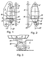
- the detachable door hinge consists of a first, through which the in the vehicle door 1 shown only hinted Door arrangement part hinged hinge half 2 and a second on which by the also only hinted at in the drawing Door pillar 3 hinged half 4 and one hinge half 2 and 4 pivotally connecting hinge pin 5.
- Der Hinge pin 5 is in the hinge half attached to the vehicle door 2 by means of a bearing bush 6 made of a maintenance-free bearing material with a rotating seat freely rotatable but immovable in the axial direction.
- the hinge pin 5 In the hinge half 4 struck on the door pillar 3 is the hinge pin 5 when the hinge is attached by means of a radially directed, form-fitting one Medium held in the hinge eye 8 in a rotationally secure manner, the hinge pin 5 a radially protruding, between the mutually facing commercial areas 9 and 10 of both hinge halves 2 and 4 engaging collar 11, which on its side facing the detachable hinge half 2 is formed towards the end of the hinge pin 5 tapering cone 12, the a corresponding conical extension in the hinge eye hole of the Hinge half 4 is assigned.
- the hinge pin 5 is also by means of a against the outer commercial area 13 of the hinge half 4 Screw 14 against automatic lifting out of their eye hole secured, whereby the security against automatic lifting by one a peripheral thread of the free end of the hinge pin 5 screwed Screw nut 14 is formed.
- the opening end stop of the door hinge is through on the hinge eyes 8 and 16 of both hinge halves 2 and 4 alternately arranged and in their open end position Motor vehicle doors cooperating stops 17 and 18 are formed.
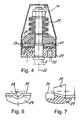
- the door lock that is structurally integrated with the detachable door hinge is formed after the commercial part of the detachable hinge half 4.
- the door arrester comprises a holding device, Braking and holding body and a carrier receiving them and a spring arrangement loading the carrier in the axial direction.
- the holding device is by an annularly curved and concentric to the axis of the hinge pin 5 arranged and having locking marks 19 career 20 formed and non-rotatable with the commercial part of the hinge half 4, in which the hinge pin 5 is rotatably supported with a seat.
- Raceway 20 acts a number of braking and designed as rolling elements Holding bodies 21 together, the braking and holding bodies 21 each a bearing axis 23 oriented transversely to the hinge axis 22 is rotatably supported are.
- the braking and holding bodies 21 are in an annular shape by means of an inner circumferential profile 24 a central recess rotatably with the over part of its the commercial part of the detachable hinge half 4 Outstanding length provided with a complementary circumferential profile Hinge pin 5 connected carrier 25 transversely to the hinge axis 22 aligned bearing axes 23 rotatably received, the brake and holding bodies 21 forming rolling elements over part of their circumference received in an axially directed groove recess 26 of the carrier 25 are.
- the track 20 forming the holding device is a through the end face on a concentric and coaxial arrangement with the hinge pin axis 22 by means of driver 33 secured against rotation on one half of the hinge Locking disc 27 formed collar and, as in particular can be seen from Figure 4 descending towards the outer circumference of the locking disc 27 arranged inclined.
- the rolling bodies forming the braking and holding bodies 21 are accordingly designed as tapered rollers and in inclination the track 20 of complementary alignment.
- the carrier 25 supporting the braking and holding bodies 21 is non-rotatable but axially slidably connected to the hinge pin 5 and in spring loaded in the axial direction.
- the attacking on the carrier 25 the braking and holding body 21 with a perpendicular to their axis of rotation 22 directed spring load acting spring assembly formed by a plate spring assembly 29, which on the one hand against one on the Free end of the hinge pin 5 screw nut 30 supported is and on the other hand attacks on the top of the carrier 25.
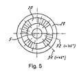
- the number of detectable opening positions of the door is due to that in the figure 5 shown arrangement of the preliminary catches 31 and locking catches 32 forming mutually opposite, locking marks 19 forming depressions determined in career 20.
- the locking device is total by a, in the embodiment shown on the outer circumference of the locking disc 27 attached protective cover 34 and thus against intrusion protected from dust or dirt.
Landscapes
- Engineering & Computer Science (AREA)
- Mechanical Engineering (AREA)
- Hinge Accessories (AREA)
- Hinges (AREA)
- Special Wing (AREA)
- Securing Of Glass Panes Or The Like (AREA)
- Specific Sealing Or Ventilating Devices For Doors And Windows (AREA)
Claims (21)
- Charnière de porte de véhicule décrochable à arrêtoir de porte intégré, avec laquelle la charnière de porte se compose d'une première moitié de charnière (2) qui peut s'accrocher sur une partie de l'arrangement de porte porte ou montant de porte et d'une deuxième moitié de charnière (4) qui peut s'accrocher sur l'autre des deux parties de l'arrangement de porte ainsi que d'une cheville de charnière (5) logé avec son appui tournant dans la première moitié de charnière (2) et pouvant être levé sans pivoter dans la deuxième moitié de charnière (4), l'arrêtoir de porte présentant un support (25) relié de manière à ne pas pouvoir pivoter à la cheville de charnière (5) pour au moins un élément de freinage et de retenue (21) disposé de manière à pouvoir s'écarter dans le sens radial par rapport à la cheville de charnière (5) et au moins un dispositif de retenue (20) comportant au moins un repère d'encliquetage (19) pour l'au moins un élément de freinage et de retenue (21), caractérisée en ce que le support (25) peut coulisser dans le sens axial le long de la cheville de charnière (5) et il est précontraint par une charge de ressort (29) dans le sens axial contre l'au moins élément de freinage et de retenue (21) en direction du dispositif de retenue (20).
- Charnière de porte de véhicule selon la revendication 1, caractérisée en ce que l'au moins un élément de freinage et de retenue (21) est logé dans le support (25) de manière à pouvoir tourner autour d'un axe (23).
- Charnière de porte de véhicule selon la revendication 1 ou 2, caractérisée en ce que l'au moins un élément de freinage et de retenue (21) est réalisé sous la forme d'un rouleau dont l'axe (23) est dirigé transversalement par rapport à l'axe de la cheville de charnière (22).
- Charnière de porte de véhicule selon l'une des revendications 1 à 3, caractérisée en ce que le support (25) est de forme annulaire et il est relié à la cheville de charnière (5) de manière à ne pas pouvoir pivoter.
- Charnière de porte de véhicule selon l'une des revendications 1 à 4, caractérisée en ce que la charge de ressort (29) à laquelle est soumis le support (25) prend appui contre un prolongement axial de la cheville de charnière (5).
- Charnière de porte de véhicule selon l'une des revendications 1 à 5, caractérisée en ce que le charge de ressort (29) est appliquée par un paquet de ressorts à lame.
- Charnière de porte de véhicule selon la revendication 6, caractérisée en ce qu'une butée pour la contrainte par ressort du support (25) et/ou le paquet de ressorts à lame (29) formant l'élément de freinage et de retenue (21) est formé par un écrou (30) vissé sur l'extrémité libre de la cheville de charnière (5).
- Charnière de porte de véhicule selon l'une des revendications 1 à 7, caractérisée en ce que les éléments de freinage et de retenue (21) sont logés dans un logement de rainure (26) dirigé dans le sens axial du support (25).
- Charnière de porte de véhicule selon l'une des revendications 1 à 8, caractérisée en ce qu'un ressort de charge disposé dans le support (25) est à chaque fois associé à chacun des éléments de freinage et de retenue (21).
- Charnière de porte de véhicule selon l'une des revendications 1 à 9, caractérisée en ce que le support (25) est relié à la cheville de charnière (5) de manière à ne pas pouvoir pivoter par le biais d'un logement agissant conjointement avec un profilé périphérique présentant un profil de section différente de la forme circulaire pure de la cheville de charnière correspondante.
- Charnière de porte de véhicule selon l'une des revendications 1 à 10, caractérisée en ce que le dispositif de retenue (20) est réalisé sous la forme d'une voie de roulement cintrée au moins en forme d'anneau partiel et disposée de manière concentrique par rapport à l'axe (22) de la cheville de charnière (5) et il est relié de manière à ne pas pouvoir pivoter à la moitié de charnière (2) dans laquelle la cheville de charnière (5) est logé avec son appui tournant de manière à pouvoir pivoter.
- Charnière de porte de véhicule selon la revendication 11, caractérisée en ce que les repères d'encliquetage (19) formés sur la voie de roulement (20) sont formés par des bosses dirigées dans le sens axial dans la voie de roulement (20).
- Charnière de porte de véhicule selon l'une des revendications 1 à 12, caractérisée en ce que la voie de roulement qui constitue un dispositif de retenue (20) est formée par la surface frontale d'une collerette configurée de manière concentrique par rapport à l'axe de la cheville de charnière (22) et disposée de manière coaxiale sur l'une des moitiés de charnière (2).
- Charnière de porte de véhicule selon la revendication 11 ou 12, caractérisée en ce que la voie de roulement (20) est formée sur un plateau d'encliquetage (27) et que le plateau d'encliquetage (27) est relié à un certain nombre d'éléments d'entraínement (33), de préférence trois, avec lesquels est reliée l'une des moitiés de charnière (2).
- Charnière de porte de véhicule selon l'une des revendications 1 à 14, caractérisée en ce que le dispositif de retenue (20) est réalisé sous la forme d'une surface annulaire périphérique et que sont prévus des éléments de freinage et de retenue (21) opposés par paires les uns aux autres.
- Charnière de porte de véhicule selon l'une des revendications 1 à 15, caractérisée en ce que le dispositif de retenue (20) est équipé d'une pluralité d'enfoncements formant des repères d'encliquetage (19) opposés par paires sont le nombre est supérieur au nombre d'éléments de freinage et de retenue (21).
- Charnière de porte de véhicule selon l'une des revendications 1 à 10, caractérisée en ce que les éléments de freinage et de retenue (21) sont réalisés sous la forme de rouleaux coniques et que le dispositif de retenue (20) est en pente descendante vers son pourtour extérieur.
- Charnière de porte de véhicule selon l'une des revendications 1 à 17, caractérisée en ce que le support qui supporte les éléments de freinage et de retenue (21) est réalisé par un ressort à lame relié à la cheville de charnière (5) de manière à ne pas pouvoir pivoter.
- Charnière de porte de véhicule selon la revendication 18, caractérisée en ce qu'au moins deux éléments de freinage et de retenue (21) sont disposés en opposition l'un de l'autre par rapport à l'axe de la cheville de charnière et en saillie dans le sens radial par rapport à la cheville de charnière (5) et sont réalisés sous la forme d'éléments glissants, et que le ressort à lame qui supporte les éléments de freinage et de retenue (21) est relié à la cheville de charnière (5) de manière à ne pas pouvoir pivoter.
- Charnière de porte de véhicule selon l'une des revendications 1 à 19, caractérisée en ce que la butée finale d'ouverture de la porte est formée par des configurations de butée (17, 18) disposées en alternance sur les deux moitiés de charnière.
- Charnière de porte de véhicule selon l'une des revendications 1 à 20, caractérisée en ce que le dispositif arrêtoir est globalement recouvert par un capot de protection (34).
Applications Claiming Priority (2)
| Application Number | Priority Date | Filing Date | Title |
|---|---|---|---|
| DE19619473 | 1996-05-14 | ||
| DE19619473A DE19619473A1 (de) | 1996-05-14 | 1996-05-14 | Mit einem aushängbaren Türscharnier baulich vereinigter Türfeststeller |
Publications (3)
| Publication Number | Publication Date |
|---|---|
| EP0807738A2 EP0807738A2 (fr) | 1997-11-19 |
| EP0807738A3 EP0807738A3 (fr) | 1999-09-29 |
| EP0807738B1 true EP0807738B1 (fr) | 2004-01-14 |
Family
ID=7794321
Family Applications (1)
| Application Number | Title | Priority Date | Filing Date |
|---|---|---|---|
| EP97106759A Expired - Lifetime EP0807738B1 (fr) | 1996-05-14 | 1997-04-24 | Charnière de porte décrochable à l'arrêtoir de porte intégré |
Country Status (4)
| Country | Link |
|---|---|
| US (1) | US6282752B1 (fr) |
| EP (1) | EP0807738B1 (fr) |
| JP (1) | JPH1046902A (fr) |
| DE (3) | DE19619473A1 (fr) |
Families Citing this family (21)
| Publication number | Priority date | Publication date | Assignee | Title |
|---|---|---|---|---|
| DE19633462B4 (de) * | 1996-05-14 | 2005-07-07 | ED. SCHARWäCHTER GMBH | Scharnier für eine Fahrzeugtür |
| DE19727041C2 (de) * | 1997-06-25 | 2000-07-20 | Scharwaechter Gmbh Co Kg | Mit einem aushängbaren Türscharnier baulich vereinigter Türfeststeller |
| DE19727098C2 (de) | 1997-06-25 | 2001-03-01 | Scharwaechter Gmbh Co Kg | Mit einem aushängbaren Türscharnier baulich vereinigter Türfeststeller |
| DE29713031U1 (de) | 1997-07-23 | 1998-12-03 | Friedr. Fingscheidt GmbH, 42551 Velbert | Scharniertürhalter für Fahrzeugtüren |
| DE29815747U1 (de) | 1998-09-02 | 2000-01-05 | Ramsauer, Dieter, 42555 Velbert | Anschraubscharnier mit Raststellung |
| DE19854602A1 (de) * | 1998-11-26 | 2000-06-08 | Scharwaechter Ed Gmbh | An ein Türscharnier angeschlossener Türfeststeller für Kraftwagentüren |
| DE19901263A1 (de) * | 1999-01-15 | 2000-07-27 | Lunke Ventra Automotive Gmbh | Gelenkverbindung, insbesondere Türscharnier, mit einer Vorrichtung zum Festsetzen eines ersten Bewegungselements |
| DE10009375C2 (de) | 2000-02-29 | 2002-10-24 | Edscha Ag | Türscharnier mit integriertem Türfeststeller |
| US6588483B2 (en) * | 2000-08-24 | 2003-07-08 | Avron Rosenberg | Door locking system |
| DE10344190A1 (de) * | 2003-09-22 | 2005-05-04 | Automobilscharniere Hasten | Schwenkscharnier |
| JP4812820B2 (ja) * | 2008-09-26 | 2011-11-09 | タキゲン製造株式会社 | ダンパー付きヒンジ |
| US8438703B2 (en) * | 2011-06-10 | 2013-05-14 | Amesbury Group, Inc. | Positionable hinge |
| EP3330463A1 (fr) | 2016-12-05 | 2018-06-06 | Innomotive Systems Hainichen GmbH | Charnière de porte |
| US10299599B2 (en) * | 2017-07-27 | 2019-05-28 | Chama Chairs Holdings LLC | Collapsible swivel chair |
| US11261645B2 (en) * | 2017-09-21 | 2022-03-01 | Warren Industries Ltd. | Hinge-based door control system |
| RU2697632C1 (ru) * | 2018-08-07 | 2019-08-15 | Акционерное общество "Информационные спутниковые системы" имени академика М.Ф. Решетнёва" | Система обезвешивания |
| EP3805497B1 (fr) * | 2019-10-10 | 2022-06-22 | MAGNA STEYR Fahrzeugtechnik AG & Co KG | Dispositif d'arrêt de porte |
| US12312847B2 (en) * | 2019-12-03 | 2025-05-27 | Steven Alonzi | Door hinge with integrated door check |
| RU2725059C1 (ru) * | 2020-03-12 | 2020-06-29 | Общество С Ограниченной Ответственностью "Гдс Восток" | Кронштейн нижний поворотный двери |
| KR102784320B1 (ko) * | 2021-12-20 | 2025-03-20 | 멀티매틱 인코퍼레이티드 | 도어 닫기 돕는 기능을 가진 자동차 도어 힌지 |
| US12473763B2 (en) * | 2022-08-23 | 2025-11-18 | Reell Precision Manufacturing Corporation | Detent hinge |
Family Cites Families (12)
| Publication number | Priority date | Publication date | Assignee | Title |
|---|---|---|---|---|
| US1078002A (en) * | 1911-09-18 | 1913-11-11 | Frederick Schrey | Hinge. |
| US1159529A (en) * | 1915-03-02 | 1915-11-09 | Frank Parizek | Hinge. |
| US2635281A (en) * | 1950-03-14 | 1953-04-21 | Morris F Feldberg | Indexing hinge |
| US3028619A (en) * | 1958-09-22 | 1962-04-10 | Schlage Lock Co | Hold open device for door closer |
| FR1203451A (fr) * | 1958-10-03 | 1960-01-19 | Pivot à positions multiples pour châssis pivotant | |
| US4532675A (en) * | 1982-05-17 | 1985-08-06 | Ford Motor Company | Door hinge with integral check |
| DE8401062U1 (de) * | 1984-01-16 | 1987-03-26 | Lunke & Sohn Gmbh, 5810 Witten | Demontierbares Kfz-Türscharnier |
| DE8627459U1 (de) * | 1986-10-15 | 1987-11-19 | Lunke & Sohn Gmbh, 5810 Witten | Türscharnier für eine Fahrzeugtür |
| US5173993A (en) * | 1991-10-30 | 1992-12-29 | Unlimited Ideas And Designs Inc. | Adjustable locking door hinge |
| DE4212181C2 (de) * | 1992-04-10 | 2002-07-18 | Audi Ag | Scharnier mit Arretierung, insbesondere für eine Kraftfahrzeug-Seitentür |
| US5269047A (en) * | 1992-06-10 | 1993-12-14 | Lu Sheng N | Hinge device for casings |
| DE19700075A1 (de) * | 1996-12-10 | 1998-06-18 | Scharwaechter Gmbh Co Kg | Türfeststeller für Kraftwagentüren |
-
1996
- 1996-05-14 DE DE19619473A patent/DE19619473A1/de not_active Withdrawn
- 1996-07-04 DE DE29611674U patent/DE29611674U1/de not_active Expired - Lifetime
-
1997
- 1997-04-24 EP EP97106759A patent/EP0807738B1/fr not_active Expired - Lifetime
- 1997-04-24 DE DE59711198T patent/DE59711198D1/de not_active Expired - Lifetime
- 1997-05-13 JP JP9122362A patent/JPH1046902A/ja not_active Withdrawn
- 1997-05-14 US US08/856,163 patent/US6282752B1/en not_active Expired - Lifetime
Also Published As
| Publication number | Publication date |
|---|---|
| DE29611674U1 (de) | 1996-09-12 |
| DE19619473A1 (de) | 1997-11-20 |
| DE59711198D1 (de) | 2004-02-19 |
| EP0807738A3 (fr) | 1999-09-29 |
| US6282752B1 (en) | 2001-09-04 |
| EP0807738A2 (fr) | 1997-11-19 |
| JPH1046902A (ja) | 1998-02-17 |
Similar Documents
| Publication | Publication Date | Title |
|---|---|---|
| EP0807738B1 (fr) | Charnière de porte décrochable à l'arrêtoir de porte intégré | |
| EP0124838A2 (fr) | Articulation | |
| DE8627459U1 (de) | Türscharnier für eine Fahrzeugtür | |
| DE4010466A1 (de) | Lagerung mindestens zweier relativ zueinander verschwenkbarer teile | |
| EP0769600B1 (fr) | Charnière de porte pour véhicule à moteur combinée constructivement avec un arrêt de porte | |
| EP0567002A1 (fr) | Arrêt de Porte de Véhicule automobile ayant un Pivot pour le Bras de celui-ci | |
| DE4406824A1 (de) | Scharnier mit Schwenkhemmung | |
| EP0825318B1 (fr) | Charnière de porte décrochable à arrêtoir de porte intégré | |
| DE19734841A1 (de) | Mit einem aushängbaren Türscharnier baulich vereinigter Türfeststeller | |
| DE19811108A1 (de) | Türscharnier mit Feststeller | |
| EP1068417B1 (fr) | Element d'arret de portiere integre a une charniere de portiere demontable | |
| DE102007022311B4 (de) | Höhenverstellbare Lagereinheit für einen Schiebeflügel | |
| EP0897045B1 (fr) | Charnière de porte décrochable à arrêt de porte intégré | |
| DE19633462B4 (de) | Scharnier für eine Fahrzeugtür | |
| DE4103198A1 (de) | Tuerbremse fuer kraftwagentueren | |
| EP0508180B1 (fr) | Appareil à rouleaux pour portes coulissantes ou analogues | |
| DE19727041C2 (de) | Mit einem aushängbaren Türscharnier baulich vereinigter Türfeststeller | |
| DE4405359C1 (de) | Beschlag zur schwenkbaren Befestigung eines Flügels einer Tür oder eines Fensters an einem Rahmen | |
| EP3574813B1 (fr) | Charnière pour un ensemble d'un siège de toilettes | |
| EP0426952B1 (fr) | Charnière de porte combinée dans sa construction avec un arrêt de porte | |
| DE29608729U1 (de) | Mit einem aushängaren Türscharnier baulich vereinigter Türfeststeller | |
| DE2923834C2 (fr) | ||
| EP0600226B1 (fr) | Arrêt de porte avec barrede torsion relié à une charnière de porte | |
| DE29614385U1 (de) | Mit einem aushängbaren Türscharnier baulich vereinigter Türfeststeller | |
| DE19642597A1 (de) | Türfeststeller für Kraftwagentüren |
Legal Events
| Date | Code | Title | Description |
|---|---|---|---|
| PUAI | Public reference made under article 153(3) epc to a published international application that has entered the european phase |
Free format text: ORIGINAL CODE: 0009012 |
|
| 17P | Request for examination filed |
Effective date: 19970424 |
|
| AK | Designated contracting states |
Kind code of ref document: A2 Designated state(s): DE ES FR GB IT SE |
|
| PUAL | Search report despatched |
Free format text: ORIGINAL CODE: 0009013 |
|
| AK | Designated contracting states |
Kind code of ref document: A3 Designated state(s): DE ES FR GB IT SE |
|
| RIC1 | Information provided on ipc code assigned before grant |
Free format text: 6E 05C 17/46 A, 6E 05D 11/10 B |
|
| RAP1 | Party data changed (applicant data changed or rights of an application transferred) |
Owner name: ED. SCHARWAECHTER GMBH |
|
| 17Q | First examination report despatched |
Effective date: 20010828 |
|
| GRAP | Despatch of communication of intention to grant a patent |
Free format text: ORIGINAL CODE: EPIDOSNIGR1 |
|
| GRAS | Grant fee paid |
Free format text: ORIGINAL CODE: EPIDOSNIGR3 |
|
| GRAA | (expected) grant |
Free format text: ORIGINAL CODE: 0009210 |
|
| AK | Designated contracting states |
Kind code of ref document: B1 Designated state(s): DE ES FR GB IT SE |
|
| PG25 | Lapsed in a contracting state [announced via postgrant information from national office to epo] |
Ref country code: IT Free format text: LAPSE BECAUSE OF FAILURE TO SUBMIT A TRANSLATION OF THE DESCRIPTION OR TO PAY THE FEE WITHIN THE PRE;WARNING: LAPSES OF ITALIAN PATENTS WITH EFFECTIVE DATE BEFORE 2007 MAY HAVE OCCURRED AT ANY TIME BEFORE 2007. THE CORRECT EFFECTIVE DATE MAY BE DIFFERENT FROM THE ONE RECORDED.SCRIBED TIME-LIMIT Effective date: 20040114 Ref country code: GB Free format text: LAPSE BECAUSE OF FAILURE TO SUBMIT A TRANSLATION OF THE DESCRIPTION OR TO PAY THE FEE WITHIN THE PRESCRIBED TIME-LIMIT Effective date: 20040114 Ref country code: FR Free format text: LAPSE BECAUSE OF FAILURE TO SUBMIT A TRANSLATION OF THE DESCRIPTION OR TO PAY THE FEE WITHIN THE PRESCRIBED TIME-LIMIT Effective date: 20040114 |
|
| REG | Reference to a national code |
Ref country code: GB Ref legal event code: FG4D Free format text: NOT ENGLISH |
|
| REF | Corresponds to: |
Ref document number: 59711198 Country of ref document: DE Date of ref document: 20040219 Kind code of ref document: P |
|
| PG25 | Lapsed in a contracting state [announced via postgrant information from national office to epo] |
Ref country code: SE Free format text: LAPSE BECAUSE OF FAILURE TO SUBMIT A TRANSLATION OF THE DESCRIPTION OR TO PAY THE FEE WITHIN THE PRESCRIBED TIME-LIMIT Effective date: 20040414 |
|
| PG25 | Lapsed in a contracting state [announced via postgrant information from national office to epo] |
Ref country code: ES Free format text: LAPSE BECAUSE OF FAILURE TO SUBMIT A TRANSLATION OF THE DESCRIPTION OR TO PAY THE FEE WITHIN THE PRESCRIBED TIME-LIMIT Effective date: 20040425 |
|
| GBV | Gb: ep patent (uk) treated as always having been void in accordance with gb section 77(7)/1977 [no translation filed] |
Effective date: 20040114 |
|
| PLBE | No opposition filed within time limit |
Free format text: ORIGINAL CODE: 0009261 |
|
| STAA | Information on the status of an ep patent application or granted ep patent |
Free format text: STATUS: NO OPPOSITION FILED WITHIN TIME LIMIT |
|
| 26N | No opposition filed |
Effective date: 20041015 |
|
| EN | Fr: translation not filed | ||
| REG | Reference to a national code |
Ref country code: DE Ref legal event code: R082 Ref document number: 59711198 Country of ref document: DE Representative=s name: BONNEKAMP & SPARING, DE Effective date: 20110812 Ref country code: DE Ref legal event code: R081 Ref document number: 59711198 Country of ref document: DE Owner name: EDSCHA ENGINEERING GMBH, DE Free format text: FORMER OWNER: ED. SCHARWAECHTER GMBH, 42855 REMSCHEID, DE Effective date: 20110812 |
|
| PGFP | Annual fee paid to national office [announced via postgrant information from national office to epo] |
Ref country code: DE Payment date: 20160421 Year of fee payment: 20 |
|
| REG | Reference to a national code |
Ref country code: DE Ref legal event code: R071 Ref document number: 59711198 Country of ref document: DE |