EP0255886A2 - Boîte encastrée dans le plancher avec un dispositif pour maintenir un ferme-porte placé là-dedans - Google Patents
Boîte encastrée dans le plancher avec un dispositif pour maintenir un ferme-porte placé là-dedans Download PDFInfo
- Publication number
- EP0255886A2 EP0255886A2 EP87110340A EP87110340A EP0255886A2 EP 0255886 A2 EP0255886 A2 EP 0255886A2 EP 87110340 A EP87110340 A EP 87110340A EP 87110340 A EP87110340 A EP 87110340A EP 0255886 A2 EP0255886 A2 EP 0255886A2
- Authority
- EP
- European Patent Office
- Prior art keywords
- floor
- holding
- floor box
- base part
- box according
- Prior art date
- Legal status (The legal status is an assumption and is not a legal conclusion. Google has not performed a legal analysis and makes no representation as to the accuracy of the status listed.)
- Granted
Links
Images

Classifications
-
- E—FIXED CONSTRUCTIONS
- E05—LOCKS; KEYS; WINDOW OR DOOR FITTINGS; SAFES
- E05F—DEVICES FOR MOVING WINGS INTO OPEN OR CLOSED POSITION; CHECKS FOR WINGS; WING FITTINGS NOT OTHERWISE PROVIDED FOR, CONCERNED WITH THE FUNCTIONING OF THE WING
- E05F3/00—Closers or openers with braking devices, e.g. checks; Construction of pneumatic or liquid braking devices
- E05F3/04—Closers or openers with braking devices, e.g. checks; Construction of pneumatic or liquid braking devices with liquid piston brakes
- E05F3/10—Closers or openers with braking devices, e.g. checks; Construction of pneumatic or liquid braking devices with liquid piston brakes with a spring, other than a torsion spring, and a piston, the axes of which are the same or lie in the same direction
-
- E—FIXED CONSTRUCTIONS
- E05—LOCKS; KEYS; WINDOW OR DOOR FITTINGS; SAFES
- E05F—DEVICES FOR MOVING WINGS INTO OPEN OR CLOSED POSITION; CHECKS FOR WINGS; WING FITTINGS NOT OTHERWISE PROVIDED FOR, CONCERNED WITH THE FUNCTIONING OF THE WING
- E05F3/00—Closers or openers with braking devices, e.g. checks; Construction of pneumatic or liquid braking devices
-
- E—FIXED CONSTRUCTIONS
- E05—LOCKS; KEYS; WINDOW OR DOOR FITTINGS; SAFES
- E05F—DEVICES FOR MOVING WINGS INTO OPEN OR CLOSED POSITION; CHECKS FOR WINGS; WING FITTINGS NOT OTHERWISE PROVIDED FOR, CONCERNED WITH THE FUNCTIONING OF THE WING
- E05F3/00—Closers or openers with braking devices, e.g. checks; Construction of pneumatic or liquid braking devices
- E05F3/22—Additional arrangements for closers, e.g. for holding the wing in opened or other position
- E05F3/225—Additional arrangements for closers, e.g. for holding the wing in opened or other position mounted at the bottom of wings, e.g. details related to seals, covers, connections to the wings, embedding in the floor
- E05F3/226—Additional arrangements for closers, e.g. for holding the wing in opened or other position mounted at the bottom of wings, e.g. details related to seals, covers, connections to the wings, embedding in the floor with means to adjust the closed position of the wing
-
- E—FIXED CONSTRUCTIONS
- E05—LOCKS; KEYS; WINDOW OR DOOR FITTINGS; SAFES
- E05Y—INDEXING SCHEME ASSOCIATED WITH SUBCLASSES E05D AND E05F, RELATING TO CONSTRUCTION ELEMENTS, ELECTRIC CONTROL, POWER SUPPLY, POWER SIGNAL OR TRANSMISSION, USER INTERFACES, MOUNTING OR COUPLING, DETAILS, ACCESSORIES, AUXILIARY OPERATIONS NOT OTHERWISE PROVIDED FOR, APPLICATION THEREOF
- E05Y2600/00—Mounting or coupling arrangements for elements provided for in this subclass
- E05Y2600/40—Mounting location; Visibility of the elements
- E05Y2600/41—Concealed
-
- E—FIXED CONSTRUCTIONS
- E05—LOCKS; KEYS; WINDOW OR DOOR FITTINGS; SAFES
- E05Y—INDEXING SCHEME ASSOCIATED WITH SUBCLASSES E05D AND E05F, RELATING TO CONSTRUCTION ELEMENTS, ELECTRIC CONTROL, POWER SUPPLY, POWER SIGNAL OR TRANSMISSION, USER INTERFACES, MOUNTING OR COUPLING, DETAILS, ACCESSORIES, AUXILIARY OPERATIONS NOT OTHERWISE PROVIDED FOR, APPLICATION THEREOF
- E05Y2600/00—Mounting or coupling arrangements for elements provided for in this subclass
- E05Y2600/40—Mounting location; Visibility of the elements
- E05Y2600/452—Mounting location; Visibility of the elements in or on the floor or wall
-
- E—FIXED CONSTRUCTIONS
- E05—LOCKS; KEYS; WINDOW OR DOOR FITTINGS; SAFES
- E05Y—INDEXING SCHEME ASSOCIATED WITH SUBCLASSES E05D AND E05F, RELATING TO CONSTRUCTION ELEMENTS, ELECTRIC CONTROL, POWER SUPPLY, POWER SIGNAL OR TRANSMISSION, USER INTERFACES, MOUNTING OR COUPLING, DETAILS, ACCESSORIES, AUXILIARY OPERATIONS NOT OTHERWISE PROVIDED FOR, APPLICATION THEREOF
- E05Y2900/00—Application of doors, windows, wings or fittings thereof
- E05Y2900/10—Application of doors, windows, wings or fittings thereof for buildings or parts thereof
- E05Y2900/13—Type of wing
- E05Y2900/132—Doors
Definitions
- the invention relates to a floor box with a device for holding a floor closer used therein.
- Floor closers are generally used in a floor box, which is already concreted into the floor during the shell and is therefore often referred to as a "cement box".
- cement box is often referred to as a "cement box”.
- the concrete is cast inaccurately.
- the floor closer in the floor box must be adjustable to bring it into the correct position for the predetermined door level.
- the object of the invention is therefore to provide a device of the type mentioned, which is easy to use and can safely absorb the occurring, sometimes large forces.
- the device is designed according to the preamble of claim 1 in accordance with the characterizing part of this claim.
- This device is assigned to the narrow end of the floor closer and as a result it is expedient to attach such a device to both ends of the floor closer.
- the longitudinal and transverse adjustment is of course carried out within a respectively predetermined adjustment range, which is also essentially determined by the play between the side walls of the floor box and the floor door closer or its housing.
- the base part is attached to a predetermined location on the floor box, provided that it is not already attached to it before concreting. The latter could be the case, for example, if the base part is made in one piece with the floor box.
- preference is given to separate manufacture of the base part and later secure fastening in the floor box.
- the floor door closer provided or connected with the holding part becomes inside a Hori after being inserted into the floor box zontalebene two-dimensionally aligned so that the door leaf used then takes the correct position to the fixed frame or the like ..
- the holding part Before the door leaf is inserted, however, the holding part is securely connected to the base part via the holding device. It must be so robust and stable that it can withstand the stresses and shocks that occur in the long term. It should not be forgotten that floor closers are supplied up to a torque of 60 Nm, for example. Despite these high requirements for a permanent connection, the holding device must be easy to operate and, if tools are required, with the commonly occurring tools.
- a further development of the invention provides that the holding part is attached to the housing of the floor door closer, in particular is screwed thereon.
- the separate production of the holding part is preferred to the housing of the floor closer before it is formed, because it is interchangeable.
- the base part is attached to one end of the floor box and extends substantially parallel to the floor box floor and to the short floor box wall.
- the holding part and the base part are preferably mounted on both narrow sides of the floor box, there is of course a base part near the two short floor box transverse walls.
- a particularly preferred embodiment of the invention is characterized in that the base part has at least one, but preferably at both ends an elongated hole extending in the longitudinal direction thereof, each elongated hole of the base part being crossed by a further elongated hole of the holding part which is offset by 90 ° , and that the holding device passes through both intersecting elongated holes and is designed as a clamping device.
- the intersecting elongated holes enable the above-mentioned two-dimensional displacement of the floor door closer in the floor box, the two displacement movements being superimposed to form an oblique movement.
- a further embodiment of the invention is characterized in that the base part has a substantially U-shaped shape, the two U-legs on the bottom of the floor box preferably stand up or at least point against it, and that between the U-legs of the base part there is the U-center piece of a holding bracket of the holding device, the U-legs of which penetrate from below the two respectively assigned elongated holes of the base and holding part, whereby a fastening element of the holding device can be attached to each U-leg of the holding bracket.
- the base part and the bracket are first attached to the floor box.
- the two U-legs of the retaining bracket then extend upwards, that is to say in the direction of an imaginary plane through the edge of the floor box.
- the holding bracket can be moved in the longitudinal direction of the base part, the displacement movement being determined by the length of the two elongated holes in the base part and the cross section of the U-legs of the holding bracket.
- the bottom door closer with or with the two holding parts is then inserted from above, an elongated hole of the holding part then being assigned to each U-leg of the holding bracket.
- the free bracket ends penetrate the intersecting elongated holes upwards. How far they survive depends on the design of the fastener.
- the actuating element of the holding device is a nut and the U-legs of the holding bracket are each provided with a corresponding thread.
- the mother can use a slotted, cross recess and / or provided with an external hexagon and preferably in the form of a screw cap. In order to facilitate access, it is preferable to make it so high that it extends close to the free edge of the floor box. Its lower end lies on a preferably machined surface around the elongated hole of the holding part and by tightening the nuts, the holding part is pressed down against the base part.
- the holding part does not have to come into contact with the base part, rather both can have a vertical distance from one another in the final assembly position, which is due to the fact that the floor closer is pressed firmly onto the inner surface of the floor box floor before each holding part reaches its assigned base part.
- the elongated holes of the holding part are advantageously edge-open at their end remote from the floor closer, i.e. H. in this case, it is a fork-shaped receptacle for the associated U-leg of the bracket. This design creates an enlarged adjustment path in the longitudinal direction of the floor closer.
- a particularly preferred embodiment of the invention results from claim 8.
- the nut When each nut of the holding device is tightened, the nut first comes into contact with the "higher" longitudinal edge closest to it. Because in the case of a nut with a right-hand thread, the longitudinal edge on the right, seen from the outside, is closer to it than the one on the left, tightening the nut initially only creates a frictional moment between the underside of the flat screw head and the surface of the right longitudinal edge that is visible in the top view. This frictional torque acts in the sense of pulling the relevant bracket U-leg against the inner slot end or in other words, due to this frictional torque the mother tries to pull the bracket towards the door closer.
- a further preferred embodiment of the invention is characterized by at least one clamping device which is connected between the holding part and the base part and is effective in an approximately vertical direction. It secures the screw connection between the fastening element and the bracket leg.
- two such clamping devices are used per holding device and they can be located in the space between the two U-legs of the bracket.
- a further embodiment of the invention provides that the tensioning device consists of a threaded bolt or the like which can be screwed into an approximately vertical thread of the holding part and which is supported on the upper side of the base part. There is therefore a tension between the holding part and the base part. It is particularly advantageous that the free end of the or each threaded bolt or the like is designed as a so-called ring cutter. As its name suggests, it can burrow into the surface of the base part, thereby securing its own adjustment in addition to the tension in the thread.
- the holding part is aligned by means of a centering projection or the like on the housing of the floor closer and is releasably connected to it by means of at least one screw or the like.
- the centering lug preferably engages in an end opening of the bottom door closer housing.
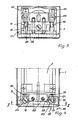
- a floor box 1 which is usually walled or concreted into the floor of a building and which is therefore often also called "concrete box", the floor door closer 2 is used from above after completion of the structural work.
- the floor box generally has an approximately cuboid shape and it consists at least essentially of a floor 3, two longitudinal side walls 4 and 5 and two transverse side walls 6, of which only the right one is shown in the drawing.
- the clear width and length of the floor box is larger than the outer dimensions of the floor door closer, so that alignment both in the sense of the double arrow 7 and the double arrow 8 within the floor box 1 is possible.
- This longitudinal and transverse Alignment is necessary in order to be able to bring the door to be connected to the floor closer into a correct position relative to its fixed frame or the like. It must not be overlooked here that the floor box 1, for example when it is concreted in, cannot necessarily assume an exact position with respect to the wall opening or the like for the door.
- the device according to the invention for holding the floor door closer 2 in the floor box 1 not only enables the floor door closer to be securely locked in the floor box and thus also on the floor, but also permits the correct longitudinal and transverse alignment within the predetermined limits.
- Essential elements of this device which brings about the holding and enables alignment, are a base part 9 which is fixedly connected or connectable to the floor box 1 and a holding part 10 which is fixedly connectable or connected to the floor door closer 2, and a holding device 11 which firmly connects both after the alignment.
- the base part 9 becomes , provided that it is not molded onto the floor box or is already attached before it is installed, is firmly connected to the floor box 1 in a suitable manner when mounting the floor door closer. 1, it is assigned to the short floor box transverse wall 6 and, when using a second device of this type, also to the opposite, other floor box transverse wall, not shown.
- Each jat is as close as possible and is preferably on Box bottom 3 attached. It has a substantially U-shaped shape, the two U-legs standing on the floor 3 of the floor box 1.
- it is equipped with two elongated holes 12 and 13 which, due to this assembly, extend parallel to the floor and to the transverse side wall 6.
- the elongated holes 20 and 21 are open towards the outside, that is to say in the longitudinal direction of the bottom door closer 2.
- the elongated holes 20 and 21 enable the floor door closer to be aligned in the longitudinal direction, while the transverse alignment is possible on account of the elongated holes 12 and 13 of the base part 9 running perpendicularly to it. Both together therefore allow two-dimensional alignment within the plane defined by the floor 3.
- the U-shaped retaining bracket 17, in particular its two U-legs 18 and 19, together with a nut 22 or 23 each form the retaining device 11 mentioned.
- the nuts are preferably designed as screw caps and they carry on their top for example a slot 24 or a cross slot for actuation by means of a corresponding screwdriver.
- at least the free ends of the U-legs 18 and 19 of the bracket 17 are provided with a corresponding thread.
- the holding part 11 is made separately and is firmly connected to the floor closer 2, for example, by two screws 25.
- An exact position fixation is achieved by means of a centering projection 26, which engages in a corresponding receptacle 27 at the front end of the bottom door closer housing 28.
- clamping device 29 Between the base part 9 and the holding part 10 is connected at least one clamping device 29 effective in the vertical direction.
- two such clamping devices are provided and each consist of a threaded bolt which is screwed into a corresponding thread of the holding part 10. It can be pressed against the holding part, in particular by means of a screwdriver, its end resting there advantageously being designed as an annular cutting edge. This digs somewhat into the upper surface of the base part 9 and this improves the clamping and holding effect of this clamping device 29, which also supports the holding device 11.
- a safe device for holding the floor door closer in the floor box 1 after the longitudinal and cross align.
- the screw 30 (FIG. 1) holds the plug-like cover 31 against shifting inwards.
- the two longitudinal edges 32 and 33 of each oblong hole 21 and 22 open towards the narrow side of the floor box 1 are not in the same plane.
- a transition region 34 is formed between these two parallel longitudinal edges 32 and 33.
- the two longitudinal edges 32 and 33 run parallel to the image plane and thus also parallel to the bottom of the door closer or the floor box 1.
- the right longitudinal edge 32 of the nut is closer than the left longitudinal edge 33 when the viewing direction 35 extends towards the inner closed end of the oblong hole 21 or 22. As a result, the nut hits first on the right longitudinal edge 32.
- the height difference is preferably about 0.3 to 0.5 mm.
Landscapes
- Hinges (AREA)
Priority Applications (1)
| Application Number | Priority Date | Filing Date | Title |
|---|---|---|---|
| AT87110340T ATE64172T1 (de) | 1986-08-08 | 1987-07-17 | Bodenkasten mit einer vorrichtung zum festhalten eines darin eingesetzten bodentuerschliessers. |
Applications Claiming Priority (4)
| Application Number | Priority Date | Filing Date | Title |
|---|---|---|---|
| DE8621301U | 1986-08-08 | ||
| DE19868621301 DE8621301U1 (de) | 1986-08-08 | 1986-08-08 | Bodenkasten mit einer Vorrichtung zum Festhalten eines in ihm eingesetzten Bodentürschließers |
| DE8706019U | 1987-04-25 | ||
| DE8706019U DE8706019U1 (de) | 1987-04-25 | 1987-04-25 | Bodenkasten mit einer Vorrichtung zum Festhalten eines darin eingesetzten Bodentürschließers |
Publications (3)
| Publication Number | Publication Date |
|---|---|
| EP0255886A2 true EP0255886A2 (fr) | 1988-02-17 |
| EP0255886A3 EP0255886A3 (en) | 1988-09-14 |
| EP0255886B1 EP0255886B1 (fr) | 1991-06-05 |
Family
ID=25951011
Family Applications (1)
| Application Number | Title | Priority Date | Filing Date |
|---|---|---|---|
| EP87110340A Expired - Lifetime EP0255886B1 (fr) | 1986-08-08 | 1987-07-17 | Boîte encastrée dans le plancher avec un dispositif pour maintenir un ferme-porte placé là-dedans |
Country Status (2)
| Country | Link |
|---|---|
| EP (1) | EP0255886B1 (fr) |
| DE (1) | DE3770539D1 (fr) |
Cited By (2)
| Publication number | Priority date | Publication date | Assignee | Title |
|---|---|---|---|---|
| DE4228386A1 (de) * | 1991-09-04 | 1993-03-11 | Dorma Gmbh & Co Kg | Einbaugehaeuse fuer einen bodentuerschliesser |
| CN107780748A (zh) * | 2016-08-25 | 2018-03-09 | 朕豪工业股份有限公司 | 关门装置的调整座 |
Family Cites Families (3)
| Publication number | Priority date | Publication date | Assignee | Title |
|---|---|---|---|---|
| GB1132464A (en) * | 1965-04-21 | 1968-11-06 | G D Peters & Co Engineering Lt | Mounting means |
| DE2806466C2 (de) * | 1978-02-15 | 1983-11-10 | Casma di V. Marinoni & Figli, 20013 Magenta | Bodentürschließer |
| DE8621301U1 (de) * | 1986-08-08 | 1986-11-20 | Gretsch-Unitas GmbH Baubeschläge, 7257 Ditzingen | Bodenkasten mit einer Vorrichtung zum Festhalten eines in ihm eingesetzten Bodentürschließers |
-
1987
- 1987-07-17 EP EP87110340A patent/EP0255886B1/fr not_active Expired - Lifetime
- 1987-07-17 DE DE8787110340T patent/DE3770539D1/de not_active Expired - Lifetime
Cited By (3)
| Publication number | Priority date | Publication date | Assignee | Title |
|---|---|---|---|---|
| DE4228386A1 (de) * | 1991-09-04 | 1993-03-11 | Dorma Gmbh & Co Kg | Einbaugehaeuse fuer einen bodentuerschliesser |
| CN107780748A (zh) * | 2016-08-25 | 2018-03-09 | 朕豪工业股份有限公司 | 关门装置的调整座 |
| US10435931B2 (en) | 2016-08-25 | 2019-10-08 | Arctek Industrial Co., Ltd. | Door closer device |
Also Published As
| Publication number | Publication date |
|---|---|
| EP0255886B1 (fr) | 1991-06-05 |
| DE3770539D1 (de) | 1991-07-11 |
| EP0255886A3 (en) | 1988-09-14 |
Similar Documents
| Publication | Publication Date | Title |
|---|---|---|
| DE69705662T2 (de) | Rollvorrichtung für Schiebetüren, Fenster oder ähnliches | |
| DE2526890C2 (de) | Elektrische Hohlwanddose | |
| DE3605987A1 (de) | Einschnappbare befestigungseinrichtung | |
| DE102008060126A1 (de) | Spannsystem | |
| AT398516B (de) | Schubkastenauszug | |
| DE2750307C2 (de) | Eck- oder T-Verbindung zweier Profile | |
| DE102017125877B4 (de) | Verankerungsbeschlag zur Verankerung in einem Werkstück | |
| DE102019122106B3 (de) | Zaunerweiterungsvorrichtung | |
| EP0255886B1 (fr) | Boîte encastrée dans le plancher avec un dispositif pour maintenir un ferme-porte placé là-dedans | |
| DE1450276B2 (fr) | ||
| EP1004743A2 (fr) | Store vertical | |
| DE3345814A1 (de) | Vorrichtung zur selbsttaetigen fehlbedienungssicherung einer an einem fenster- od.dgl. -fluegel vorgesehenen stellstange | |
| DE10228888B4 (de) | Punkthalter für Verbundsicherheitsglasplatte | |
| DE8621301U1 (de) | Bodenkasten mit einer Vorrichtung zum Festhalten eines in ihm eingesetzten Bodentürschließers | |
| DE8706019U1 (de) | Bodenkasten mit einer Vorrichtung zum Festhalten eines darin eingesetzten Bodentürschließers | |
| DE8516029U1 (de) | Längsführung, insbesondere für eine Kreissäge | |
| EP3260713B1 (fr) | Dispositif de fixation rapide du type vis-ecrou, en particulier pour la fixation d'un cadre sur une unite d'alimentation souterraine | |
| DE3838509C1 (en) | Connecting bolt for shuttering panels | |
| DE69002342T2 (de) | Befestigungsvorrichtung durch Zusammenschrauben auf einem Profil, insbesondere auf einem Elektrizitätsschrank. | |
| DE9113128U1 (de) | Gestell aus mit Verbindungsschlössern verbundenen Profilstangen | |
| DE2508274A1 (de) | Geruestverbindung | |
| DE19544719C1 (de) | Einrichtung zum Befestigen eines Fenstereinsatzes | |
| DE2118419A1 (de) | Treppengeländer | |
| DE1659442B1 (de) | Vorrichtung zur Eckverbindung zweier Profilstaebe eines Rahmens fuer Fenster,Tueren od.dgl. | |
| DE29709443U1 (de) | Rolladenausstellvorrichtung |
Legal Events
| Date | Code | Title | Description |
|---|---|---|---|
| PUAI | Public reference made under article 153(3) epc to a published international application that has entered the european phase |
Free format text: ORIGINAL CODE: 0009012 |
|
| AK | Designated contracting states |
Kind code of ref document: A2 Designated state(s): AT BE CH DE FR GB IT LI NL |
|
| PUAL | Search report despatched |
Free format text: ORIGINAL CODE: 0009013 |
|
| AK | Designated contracting states |
Kind code of ref document: A3 Designated state(s): AT BE CH DE FR GB IT LI NL |
|
| 17P | Request for examination filed |
Effective date: 19880805 |
|
| 17Q | First examination report despatched |
Effective date: 19900503 |
|
| GRAA | (expected) grant |
Free format text: ORIGINAL CODE: 0009210 |
|
| AK | Designated contracting states |
Kind code of ref document: B1 Designated state(s): AT BE CH DE FR GB IT LI NL |
|
| REF | Corresponds to: |
Ref document number: 64172 Country of ref document: AT Date of ref document: 19910615 Kind code of ref document: T |
|
| GBT | Gb: translation of ep patent filed (gb section 77(6)(a)/1977) | ||
| REF | Corresponds to: |
Ref document number: 3770539 Country of ref document: DE Date of ref document: 19910711 |
|
| ITF | It: translation for a ep patent filed | ||
| ET | Fr: translation filed | ||
| K2C3 | Correction of patent specification (complete document) published |
Effective date: 19910605 |
|
| PLBE | No opposition filed within time limit |
Free format text: ORIGINAL CODE: 0009261 |
|
| STAA | Information on the status of an ep patent application or granted ep patent |
Free format text: STATUS: NO OPPOSITION FILED WITHIN TIME LIMIT |
|
| 26N | No opposition filed | ||
| PGFP | Annual fee paid to national office [announced via postgrant information from national office to epo] |
Ref country code: GB Payment date: 19920611 Year of fee payment: 6 Ref country code: CH Payment date: 19920611 Year of fee payment: 6 |
|
| PGFP | Annual fee paid to national office [announced via postgrant information from national office to epo] |
Ref country code: AT Payment date: 19920616 Year of fee payment: 6 |
|
| PGFP | Annual fee paid to national office [announced via postgrant information from national office to epo] |
Ref country code: BE Payment date: 19920624 Year of fee payment: 6 |
|
| PGFP | Annual fee paid to national office [announced via postgrant information from national office to epo] |
Ref country code: LU Payment date: 19920714 Year of fee payment: 6 |
|
| PGFP | Annual fee paid to national office [announced via postgrant information from national office to epo] |
Ref country code: NL Payment date: 19920731 Year of fee payment: 6 |
|
| EPTA | Lu: last paid annual fee | ||
| PG25 | Lapsed in a contracting state [announced via postgrant information from national office to epo] |
Ref country code: GB Effective date: 19930717 Ref country code: AT Effective date: 19930717 |
|
| PG25 | Lapsed in a contracting state [announced via postgrant information from national office to epo] |
Ref country code: LI Effective date: 19930731 Ref country code: CH Effective date: 19930731 Ref country code: BE Effective date: 19930731 |
|
| BERE | Be: lapsed |
Owner name: GRETSCH UNITAS G.M.B.H. BAUBESCHLAGE Effective date: 19930731 |
|
| PG25 | Lapsed in a contracting state [announced via postgrant information from national office to epo] |
Ref country code: NL Effective date: 19940201 |
|
| GBPC | Gb: european patent ceased through non-payment of renewal fee |
Effective date: 19930717 |
|
| NLV4 | Nl: lapsed or anulled due to non-payment of the annual fee | ||
| REG | Reference to a national code |
Ref country code: CH Ref legal event code: PL |
|
| PGFP | Annual fee paid to national office [announced via postgrant information from national office to epo] |
Ref country code: FR Payment date: 19940622 Year of fee payment: 8 |
|
| PG25 | Lapsed in a contracting state [announced via postgrant information from national office to epo] |
Ref country code: FR Effective date: 19960430 |
|
| REG | Reference to a national code |
Ref country code: FR Ref legal event code: ST |
|
| REG | Reference to a national code |
Ref country code: FR Ref legal event code: ST |
|
| REG | Reference to a national code |
Ref country code: FR Ref legal event code: ST |
|
| PGFP | Annual fee paid to national office [announced via postgrant information from national office to epo] |
Ref country code: DE Payment date: 20020711 Year of fee payment: 16 |
|
| PG25 | Lapsed in a contracting state [announced via postgrant information from national office to epo] |
Ref country code: DE Free format text: LAPSE BECAUSE OF NON-PAYMENT OF DUE FEES Effective date: 20040203 |
|
| PG25 | Lapsed in a contracting state [announced via postgrant information from national office to epo] |
Ref country code: IT Free format text: LAPSE BECAUSE OF NON-PAYMENT OF DUE FEES;WARNING: LAPSES OF ITALIAN PATENTS WITH EFFECTIVE DATE BEFORE 2007 MAY HAVE OCCURRED AT ANY TIME BEFORE 2007. THE CORRECT EFFECTIVE DATE MAY BE DIFFERENT FROM THE ONE RECORDED. Effective date: 20050717 |