EP0255912A2 - Vorrichtung zur magnetischen Aufzeichnung und Wiedergabe - Google Patents
Vorrichtung zur magnetischen Aufzeichnung und Wiedergabe Download PDFInfo
- Publication number
- EP0255912A2 EP0255912A2 EP87110923A EP87110923A EP0255912A2 EP 0255912 A2 EP0255912 A2 EP 0255912A2 EP 87110923 A EP87110923 A EP 87110923A EP 87110923 A EP87110923 A EP 87110923A EP 0255912 A2 EP0255912 A2 EP 0255912A2
- Authority
- EP
- European Patent Office
- Prior art keywords
- signal
- video head
- image
- memory element
- control means
- Prior art date
- Legal status (The legal status is an assumption and is not a legal conclusion. Google has not performed a legal analysis and makes no representation as to the accuracy of the status listed.)
- Withdrawn
Links
- 230000001360 synchronised effect Effects 0.000 claims abstract description 5
- 230000003213 activating effect Effects 0.000 claims description 2
- 238000009295 crossflow filtration Methods 0.000 description 20
- 230000033458 reproduction Effects 0.000 description 15
- 230000004044 response Effects 0.000 description 6
- 238000010586 diagram Methods 0.000 description 3
- 230000010355 oscillation Effects 0.000 description 2
- 230000000694 effects Effects 0.000 description 1
- 230000006870 function Effects 0.000 description 1
- 230000003252 repetitive effect Effects 0.000 description 1
Images



Classifications
-
- H—ELECTRICITY
- H04—ELECTRIC COMMUNICATION TECHNIQUE
- H04N—PICTORIAL COMMUNICATION, e.g. TELEVISION
- H04N5/00—Details of television systems
- H04N5/76—Television signal recording
- H04N5/91—Television signal processing therefor
- H04N5/93—Regeneration of the television signal or of selected parts thereof
- H04N5/937—Regeneration of the television signal or of selected parts thereof by assembling picture element blocks in an intermediate store
Definitions
- the present invention relates to a magnetic recording and reproducing apparatus and, more particularly, to a slow-motion device for use in a magnetic recording and reproducing apparatus which is suitable for effecting noiseless slow-motion reproduction using a memory.
- the prior art of the type described above suffers from the problem that, in order to realize unblurred noiseless slow-motion by reproducing the image signal for one field only in each read cycle, it is necessary to provide a complicated head arrangement, intermittent drive control means and a compensating system for eliminating horizontal and vertical swings of the reproduced image due to the variation of period in the horizontal and vertical synchronizing signals during the intermittent drive.
- the above-described problems may be overcome by storing a memory with a steady image signal for one field during each stop of the intermittent drive and repeatedly reading the stored image signal during the feed of the tape in the intermittent drive.
- the signal which determines the start point for reading and writing the image signal for one field must by synchronized with a point which corresponds to a blanking point that does not appear on the TV screen in order to obtain a continuous image, and the signal must also be synchronized with the reproduced image signal because the image signal is stored in the memory in synchronism with the intermittent drive.
- Examples of the signals which satisfy the above-described requirements may be the vertical synchronizing signal reproduced from the magnetic tape and a signal for switching the video head for recording and reproducing the image signal such as that specified in the VHS standard for VTR.
- the present invention provides a magnetic recording and reproducing apparatus designed to record and reproduce an image signal on and from a magnetic tape in an amount that corresponds to a predetermined unit of image in each read or write cycle, which comprises: a video head for reproducing the image signal from the magnetic tape; video head position detecting means for detecting the position of the video head; a rotary drum having the video head installed thereon; rotary drum control means for controlling the rotation of the rotary drum; reference circuit means for obtaining a signal defining a reference used to determine the phase of the video head; a memory element sufficient to store the image signal obtained from the video head in an amount corresponding to the predetermined unit of image; means for storing the image signal for the predetermined unit of image in the memory element; control means for controlling the operation of reading and writing the image signal from and into the memory element; means for synchronizing the control means with the video head position detecting means when the rotary drum control means is controlling the rotary drum on the basis of the signals respectively output from the reference circuit means and the video head position detecting means
- a counter which is initialized in response to a head switching signal in the normal reproduction mode and which is activated so as to operate at the same period as that of a cylinder motor in the slow-motion reproduction moade, so that an amount of image signal corresponding to a predetermined unit of image, e.g., one field, is stored in the memory from a start point which is set by the counter after intermittent drive has been completed and it has become possible to obtain a steady image signal.
- the signal stored in the memory is read out from a point of time which is set by the same counter, and the above-described operation is repeated from a point of time when the subsequent intermittent drive has been completed and it has become possible to obtain a steady image signal, thereby achieving slow-motion reproduction which is free from vertical and horizontal swings.
- the counter which provides references on the basis of which the read and write operation in relation to the memory are carried out is initialized in the normal reproduction mode and activated so as to operate at the same period as that of the rotation of the cylinder motor.
- the starting timing for each of the read and write operations in relation to the memory is set on the basis of the operation of this counter.
- the start timing is determined on the basis of the operation of the counter to store an amount of image signal which corresponds to one field, and the data stored in the memory is output on the basis of the timing set by the counter until an image signal is obtained after the subsequent intermittent drive.
- any unsteady image signal which may be generated during intermittent drive is prevented from being output to the outside, and a steady image signal is output from the memory on the basis of the timing determined by the counter.
- a steady image signal is output from the memory on the basis of the timing determined by the counter.
- the reference numeral l denotes a magnetic tape, 2, 3 video heads, 4 a cylinder motor, 5, 6 magnets, 7 a head switching signal generator, 8, l7, 20 switches, 9, l9 drive circuits, l0 a control circuit, ll a reference signal circuit, l2 a counter circuit, l3 a signal processing circuit, l4 and A/D converter, l5 a memory circuit, l6 a D/A converter, l8 a capstan motor, 2l a motor control circuit, 22 an intermittent drive circuit, and 30, 3l, 32, 33, 35, 36 signals.
- control circuit l0 controls the cylinder motor 4 through the drive circuit 9 so that the motor 4 is rotated at a predetermined speed, and the control circuit l0 also effects control so that the signal 30 is phase-locked with respect to the reference signal 3l which is output from the reference signal circuit ll.
- the video heads 2 and 3 are arranged to rotate together with the cylinder motor 4 and adapted to alternately reproduce the signal recorded on the magnetic tape l and output the read signals to the switch 8.
- the switch 8 is activated in response to the signal 30 so as to form the signals from the video heads 2 and 3 into one serial signal. This signal is then converted into an image signal in the signal processing circuit l3.
- the signal 30 is formed by the cooperation of the head switching signal generator 7 and the magnets 5, 6 which are installed so as to rotate together with the cylinder motor 4 and to indicate the positions of the video heads 2 and 3, respectively.
- the signal 30 is employed to select either one of the video heads 2 and 3 tracing the magnetic tape l.
- the signal 36 is a slow-motion reproduction command which is normally at the low level to connect the switch l7 to the terminal e . Accordingly, the signal output from the signal processing circuit l3 is output to the outside via the switch l7.
- the signal 36 also controls the switch 20 so that the switch 20 is connected to the terminal c when the signal 36 is at the low level.
- the capstan motor l8 is controlled by the motor control circuit 2l through the drive circuit l9 so that the motor l8 is rotated at a predetermined speed to drive the magnetic tape l.
- the signal 36 When a slow-motion reproduction instruction is issued from the user, the signal 36 is raised to the high level. In consequence, the switch 20 is connected to the terminal d , and the capstan motor l8 is caused to feed the magnetic tape l intermittently under the control of the intermittent drive circuit 22. Accordingly, the video heads 2 and 3 change the tracks from which they are to reproduce signals every time the tape l is fed intermittently. Further, the signal 36 changes the position of the switch l7 from the terminal e to the terminal f , thus allowing the signal from the D/A converter l6 to be output to the outside.
- the intermittent drive circuit 22 is similar to the system described in Japanese Patent Laid-Open No. 20l8/l979 mentioned as a prior art and therefore description of the arrangement thereof is omitted.
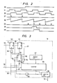
- Fig. 2 is a waveform chart showing signals at essential portions of the arrangement shown in Fig. l.
- the reference numeral 37 represents an internal signal used inside the counter circuit l2
- 38 schematically shows the count of the counter in the counter circuit l2
- 39 represents an internal signal used in the memory circuit l5.
- the counter circuit l2 when the signal 36 is at the low level, is initialized in response to the signal 37 which is generated synchronously with the leading edge of the signal 30, and the counter circuit l2 operates in the manner shown by the count 38.
- the counter circuit l2 When the signal 36 is raised to the high level, the signal 37 is fixed to the low level, so that the initialization of the counter circuit l2 is suspended.
- the counter circuit l2 counts the same clocks as those which are counted by the reference signal circuit ll and repeats the counting operation at the same period as that of the reference signal circuit ll. More specifically, the counter circuit l2 operates with a predetermined phase difference with respect to the signal 3l at all times.
- the counter circuit l2 indicates a point where the leading edge of the signal 30 should be phase-locked with respect to the signal 3l in a steady state of the magnetic tape l.
- the counter circuit l2 generates the signal 33 which has pulses at two points, i.e., a first point that indicates the leading edge of the signal 30 and a second point that is behind the first point by a period of time which corresponds to one field.
- the signal 33 is input to the memory circuit l5.
- the intermittent drive circuit 22 causes the capstan motor l9 to be driven intermittently and further outputs the signal 35 which enables writing of the image signal when the control system has returned to the steady state after intermittent drive.
- a judgement as to whether or not the control system has become steady can readily be made by measuring the time after intermittent drive has been completed, and therefore description thereof is omitted herein.
- the signal 35 is shaped into the signal 39 by the use of the signal 33.
- the period during which the signal 39 is at the high level is the write period for the memory circuit l5, while the period during which the signal 39 is at the low level is the read period for the memory circuit l5.
- the signal output from the signal processing circuit l3 is digitalized in the A/D converter l4 and, when the signal 39 is at the high level, the digitalized signal is written into the memory circuit l5 and, at the same time, converted into an analog signal in the D/A converter l6 and output to the outside via the switch l7, whereas, when the signal 39 is at the low level, the signal read out from the memory circuit l5 is output to the outside in the same way.
- the counter circuit l2 will be described in detail with reference to Fig. 3.
- the reference numerals 50, 5l and 54 denote resettable T flip-flops (hereinafter referred to as "TFFs"), 52, 55 OR gates, 53, 56 inverters, 57 a preset circuit, 58 a counter, 59 an AND gate, 60 logical circuits, and 65 to 67 signals.
- TFFs resettable T flip-flops
- the reference numeral 32 denotes a clock signal which is input to the counter 58 and also to the TFFs 5l and 54 through the inverter 53. Assuming that the initial state of the Q output of each of the TFFs 50 and 5l is the low level (i.e., the signals 65 and 37 are at the low level), the operation of the counter circuit l2 will be described with reference to Fig. 4 which is a waveform chart showing signals at essential portions of the arrangement shown in Fig. 3.
- the TFF 50 samples the state of the D terminal in synchronism with the rise of the signal 30. Since the D terminal is at the high level, the signal 65 is shifted from the low level to the high level. The TFF 5l samples the signal 65 in synchronism with the fall of the signal 32, and the signal 37 is consequently raised to the high level. Since the signal 37 is input to the reset terminal of the TFF 50 through the OR gate 52, when the signal 37 becomes high in level, the signal 65 is shifted to the low level. The TFF 5l samples the signal 65 again, and the signal 37 is shifted to the low level. Thus, the TFF 50 and 5l are returned to their initial states to await the input of the next leading edge of the signal 30.
- the signal 37 is also input to the counter 58 through the OR gate 55.
- the counter 58 is set to a value specified by the preset circuit 57.
- the counter 58 counts the number of rises of the clock signal 32, but the output of the logical circuits 60 is fixed to the low level by the signal 36.
- the AND gate 59 outputs a high-level signal when all the outputs of the counter 58 are high in level, since the TFF 54 is in a reset state, the AND gate 59 does not contribute to the operation.
- the logical circuits 60 are allowed to output pulses in the form of the signal 33 in accordance with the count of the counter 58, while the TFF 50 and 5l are reset, and the signals 65 and 37 are fixed to the low level.
- the TFF 54 is released of reset.
- the signal 677 output from the AND gate 59 is raised to the high level.
- the TFF 54 samples the signal 67 in synchronism with the fall of the clock signal 32 to obtain the signal 66.
- the counter 58 is set to the value specified by the present circuit 57.
- the signal 67 is shifted to the low level, and the signal 66 is also shifted to the low level in synchronism with the subsequent fall of the signal 32.
- the counter 58 starts counting in synchronism with the rise of the clock signal 32, and when all the outputs of the counter 58 are high in level, the above-described operation is repeated.
- the value which is specified by the present circuit l5 is set so that the counter 58 performs the above-described operation at the same period as that of the signal 30 which is output from the reference signal circuit ll.
- the counted values output from the counter 58 are ORed in the logical circuits 60 so that pulses are respectively generated at two points, i.e., a first point corresponding to the initialization and a second point which is behind the first point by a period of time that corresponds to one field, and the logical circuits 60 output the result of the ORing in the form of the signal 33 to the memory circuit l5.
- the reference numerals 70 and 72 denote inverters, 7l, 74 TFFs, 73 a memory, 75 an address counter, 76 a memory controller, 77 a switch, and 80 a signal, while the numeral 8l in Fig. 6 schematically shows the count of the address counter 75.
- the memory 73 is a widely used general-purpose RAM of the type wherein a memory element into which data is to be written is specified with an address.
- the TFFs 7l and 75 are in a reset state and therefore do not accept the signal 33.
- the TFF 7l is enabled to sample the signal 33 in response to the inverted signal which is formed in the inverter 72 by inverting the signal 32. Since the signal 33 is the OR of the output signals of the counter 58 as described above, as shown by the signal 33 in Fig. 6, the signal 33 changes in synchronism with the rise of the signal 32 and is sampled by the TFF 7l in synchronism with the fall of the signal 32 to obtain the signal 80.
- the signal 80 resets the address counter 75 (see 8l in Fig. 6).
- the address counter 75 after releasing of reset, is allowed to count up in synchronism with the rise of the clock signal 32 to thereby specify through the memory controller 76 a memory element in the memory 73 to or from which data is to be written or read.
- the signal 80 is also input to the TFF 74 to sample the signal 35.
- the signal 35 is shaped into the signal 39 on the basis of the signal 80.
- the signal 39 indicates a period during which a steady image signal can be obtained, the period corresponding to one field.
- the signal 39 controls through the memory controller 76 the operation of reading and writing data (the output of the A/D converter l4) in relation to the memory 73. It is assumed that, when the signal 39 is at the high level, writing of data is carried out, whereas, when the signal 39 is at the low level, reading of data is performed. In the case where the memory 73 does not enable reading and writing at the same time, when data is being written, no output is obtained.
- the position of the switch 77 is changed from the terminal h to the terminal g , whereby the output signal from the A/D converter l4 is transmitted to the D/A converter l6 and output to the outside as an image signal.
- the memory 73 is in the read mode, and the switch 77 is connected to the terminal h .
- the data stored in the memory 73 is output to the outside through the data converter l6. In this way, a steady image signal can be read from and written into the memory 73 in an amount which corresponds to one field.
- the counter circuit l2 is initializ ed in response to the head switching signal 30, whereas, when the slow-motion reproduction mode is started, the initialization is suspended, and the data reading and writing operations in relation to the memory circuit l5 are controlled on the basis of the signal 33, whereby it is possible to obtain a steady image signal which is free from swings, skew and vertical shift.
- the initialization of the counter circuit l2 is effected in synchronism with the rise of the head switching signal
- the flal or both leading and trailing edges of the signal may also be used for the initialization.
- the rise of the head switching signal is employed in order to find a vertical blanking point which does not appear on the TV screen; therefore, the initialization may also be effected on the basis of the vertical synchronizing signal.
Landscapes
- Engineering & Computer Science (AREA)
- Multimedia (AREA)
- Signal Processing (AREA)
- Television Signal Processing For Recording (AREA)
Applications Claiming Priority (2)
| Application Number | Priority Date | Filing Date | Title |
|---|---|---|---|
| JP61185098A JPH0789667B2 (ja) | 1986-08-08 | 1986-08-08 | 磁気記録再生装置 |
| JP185098/86 | 1986-08-08 |
Publications (2)
| Publication Number | Publication Date |
|---|---|
| EP0255912A2 true EP0255912A2 (de) | 1988-02-17 |
| EP0255912A3 EP0255912A3 (de) | 1990-10-10 |
Family
ID=16164813
Family Applications (1)
| Application Number | Title | Priority Date | Filing Date |
|---|---|---|---|
| EP19870110923 Withdrawn EP0255912A3 (de) | 1986-08-08 | 1987-07-28 | Vorrichtung zur magnetischen Aufzeichnung und Wiedergabe |
Country Status (3)
| Country | Link |
|---|---|
| US (1) | US4912571A (de) |
| EP (1) | EP0255912A3 (de) |
| JP (1) | JPH0789667B2 (de) |
Families Citing this family (9)
| Publication number | Priority date | Publication date | Assignee | Title |
|---|---|---|---|---|
| US5214515A (en) * | 1986-10-28 | 1993-05-25 | Mitsubishi Denki Kabushiki Kaisha | Video signal recording/reproducing apparatus |
| US5355256A (en) * | 1987-06-24 | 1994-10-11 | Canon Kabushiki Kaisha | Video signal reproducing apparatus having diverse still picture reproduction modes |
| JP2564874B2 (ja) * | 1988-02-09 | 1996-12-18 | キヤノン株式会社 | ビデオ信号記録再生装置 |
| DE69128161T2 (de) * | 1990-03-19 | 1998-04-09 | Canon Kk | Standbild-Wiedergabegerät |
| JP3166247B2 (ja) * | 1991-12-12 | 2001-05-14 | ソニー株式会社 | ビデオテープレコーダ |
| US5625504A (en) | 1992-09-10 | 1997-04-29 | Hitachi, Ltd. | Magnetic recording and reproducing system |
| CN1118498A (zh) * | 1993-08-26 | 1996-03-13 | 株式会社金星社 | 在慢放模式中用于控制跟踪的装置及方法 |
| CN1068449C (zh) * | 1996-01-17 | 2001-07-11 | 三星电子株式会社 | 磁带记录设备的磁头位置检测装置 |
| KR100296967B1 (ko) * | 1999-01-30 | 2001-09-26 | 구자홍 | 멀티미디어 스트림의 다단계 요약 세그먼트 정보 스킴 구성 방법 및 구성된 다단계 요약 세그먼트 정보 스킴으로 부터 요약 스트림 발생 방법과 이러한 방법에 의해 제공되는 다단계 요약 스트림의 브라우징/녹화/편집 장치 |
Family Cites Families (8)
| Publication number | Priority date | Publication date | Assignee | Title |
|---|---|---|---|---|
| GB1587798A (en) * | 1977-05-31 | 1981-04-08 | Victor Company Of Japan | Tape driving system in a recording and/or reproducing apparatus |
| DE3045543A1 (de) * | 1980-12-03 | 1982-07-01 | Robert Bosch Gmbh, 7000 Stuttgart | Verfahren und anordnung zur wiedergabe von auf einem aufzeichnungstraeger in einzelnen spuren aufgezeichneten videosignalen |
| US4594616A (en) * | 1980-12-15 | 1986-06-10 | Rca Corporation | Recording of timing signals synchronous with a rotary recorder member |
| AT376860B (de) * | 1983-03-15 | 1985-01-10 | Philips Nv | System zum wiedergeben von auf einem magnetband gespeicherten informationssignalen |
| US4733312A (en) * | 1984-04-24 | 1988-03-22 | Matsushita Electric Industrial Co., Ltd. | Time-base corrector |
| JPS6199481A (ja) * | 1984-10-20 | 1986-05-17 | Sony Corp | 自動位相制御回路 |
| JPH0650911B2 (ja) * | 1984-10-26 | 1994-06-29 | ソニー株式会社 | 再生映像信号処理装置 |
| JPS61281688A (ja) * | 1985-06-06 | 1986-12-12 | Victor Co Of Japan Ltd | 磁気記録再生装置の疑似垂直同期信号生成方法及び疑似垂直同期信号生成回路 |
-
1986
- 1986-08-08 JP JP61185098A patent/JPH0789667B2/ja not_active Expired - Lifetime
-
1987
- 1987-07-28 EP EP19870110923 patent/EP0255912A3/de not_active Withdrawn
- 1987-08-04 US US07/081,446 patent/US4912571A/en not_active Expired - Fee Related
Also Published As
| Publication number | Publication date |
|---|---|
| JPS6342292A (ja) | 1988-02-23 |
| JPH0789667B2 (ja) | 1995-09-27 |
| EP0255912A3 (de) | 1990-10-10 |
| US4912571A (en) | 1990-03-27 |
Similar Documents
| Publication | Publication Date | Title |
|---|---|---|
| US4636874A (en) | System for reproducing information signals on a magnetic tape which incrementally adjusts, in a plurality of steps the speed of the magnetic tape and the positioning and rotational speed of the magnetic head upon a change of mode | |
| EP0169479B1 (de) | Verfahren und Vorrichtung zum automatischen Spurnachlauf für magnetisches Aufzeichnungs- und Wiedergabegerät | |
| EP0209796A2 (de) | Magnetisches Wiedergabegerät | |
| JPS6110379A (ja) | スキユ−歪除去装置 | |
| KR870004633A (ko) | 메모리를 이용한 비디오 테이프 레코더의 저속재생장치 | |
| US4912571A (en) | A memory controlling apparatus for a magnetic recording and reproducing apparatus | |
| US4853914A (en) | Time base correction system with coarse and fine correction | |
| JPS645274A (en) | Recording information reproducing device | |
| NL8001145A (nl) | Servobesturingsschakeling voor een signaalopneem- en/of -weergeefinrichting met een of meer roteerbare signaaltransducenten. | |
| JPH0834573B2 (ja) | トラッキング制御装置 | |
| EP0241130B1 (de) | Gerät zum Korrigieren der Zeitfehler von aufeinanderfolgenden Datenblöcken | |
| JP2557842B2 (ja) | 回転ヘツドの回転位相発生装置 | |
| JPH0334310B2 (de) | ||
| US4679098A (en) | Video tape transport servo for variable tape speed control | |
| US5065385A (en) | Time base control system with coarse and fine correction for a spindle servo | |
| US6278567B1 (en) | Apparatus and method for recording a video signal on a recording medium | |
| US5862294A (en) | Video signal reproducing apparatus in image fast locking system | |
| EP0279885B1 (de) | Video-Signalwiedergabegerät | |
| US5189568A (en) | Method and apparatus for generating frame control signals in a multihead videotape recorder using multiple video signal tracks for each video frame | |
| JPS60150208A (ja) | 磁気記録再生装置のヘツド切換信号生成回路 | |
| KR910002342B1 (ko) | 자기 기록 재생 장치 | |
| WO1979000213A1 (en) | Video editing system | |
| KR0133412B1 (ko) | 브이씨알의 엑스거리 자동조정방법 및 장치 | |
| SU1582199A2 (ru) | Устройство стабилизации скорости движени носител магнитной записи | |
| JPS60123130A (ja) | ビデオテープレコーダの再生装置 |
Legal Events
| Date | Code | Title | Description |
|---|---|---|---|
| PUAI | Public reference made under article 153(3) epc to a published international application that has entered the european phase |
Free format text: ORIGINAL CODE: 0009012 |
|
| 17P | Request for examination filed |
Effective date: 19870728 |
|
| AK | Designated contracting states |
Kind code of ref document: A2 Designated state(s): DE GB |
|
| PUAL | Search report despatched |
Free format text: ORIGINAL CODE: 0009013 |
|
| AK | Designated contracting states |
Kind code of ref document: A3 Designated state(s): DE GB |
|
| STAA | Information on the status of an ep patent application or granted ep patent |
Free format text: STATUS: THE APPLICATION HAS BEEN WITHDRAWN |
|
| 18W | Application withdrawn |
Withdrawal date: 19910911 |
|
| R18W | Application withdrawn (corrected) |
Effective date: 19910911 |
|
| RIN1 | Information on inventor provided before grant (corrected) |
Inventor name: NISHIJIMA, HIDEO Inventor name: OKAMOTO, KANEYUKI Inventor name: MASUDA, MICHIO Inventor name: SEKIYA, MASATAKA Inventor name: KOBAYASHI, JUN |