EP0255991A2 - Dispositif de sécurité pour portes de moyens de transport public - Google Patents
Dispositif de sécurité pour portes de moyens de transport public Download PDFInfo
- Publication number
- EP0255991A2 EP0255991A2 EP87830190A EP87830190A EP0255991A2 EP 0255991 A2 EP0255991 A2 EP 0255991A2 EP 87830190 A EP87830190 A EP 87830190A EP 87830190 A EP87830190 A EP 87830190A EP 0255991 A2 EP0255991 A2 EP 0255991A2
- Authority
- EP
- European Patent Office
- Prior art keywords
- door
- peg
- track
- safety device
- pneumatic system
- Prior art date
- Legal status (The legal status is an assumption and is not a legal conclusion. Google has not performed a legal analysis and makes no representation as to the accuracy of the status listed.)
- Withdrawn
Links
- 230000007257 malfunction Effects 0.000 description 3
- 230000002498 deadly effect Effects 0.000 description 1
Images


Classifications
-
- E—FIXED CONSTRUCTIONS
- E05—LOCKS; KEYS; WINDOW OR DOOR FITTINGS; SAFES
- E05F—DEVICES FOR MOVING WINGS INTO OPEN OR CLOSED POSITION; CHECKS FOR WINGS; WING FITTINGS NOT OTHERWISE PROVIDED FOR, CONCERNED WITH THE FUNCTIONING OF THE WING
- E05F15/00—Power-operated mechanisms for wings
- E05F15/50—Power-operated mechanisms for wings using fluid-pressure actuators
- E05F15/56—Power-operated mechanisms for wings using fluid-pressure actuators for horizontally-sliding wings
- E05F15/565—Power-operated mechanisms for wings using fluid-pressure actuators for horizontally-sliding wings for railway-cars
-
- E—FIXED CONSTRUCTIONS
- E05—LOCKS; KEYS; WINDOW OR DOOR FITTINGS; SAFES
- E05Y—INDEXING SCHEME ASSOCIATED WITH SUBCLASSES E05D AND E05F, RELATING TO CONSTRUCTION ELEMENTS, ELECTRIC CONTROL, POWER SUPPLY, POWER SIGNAL OR TRANSMISSION, USER INTERFACES, MOUNTING OR COUPLING, DETAILS, ACCESSORIES, AUXILIARY OPERATIONS NOT OTHERWISE PROVIDED FOR, APPLICATION THEREOF
- E05Y2900/00—Application of doors, windows, wings or fittings thereof
- E05Y2900/50—Application of doors, windows, wings or fittings thereof for vehicles
- E05Y2900/51—Application of doors, windows, wings or fittings thereof for vehicles for railway cars or mass transit vehicles
Definitions
- This invention relates to a safety device for application to a door of a municipal means of public transport, in particular a door of the so-called inward rototranslation type operated by a pneumatic system, wherein a door wing is provided with a top-mounted peg guided for sliding movement in a track overlying the door, said device being effective to inhibit opening of the door in case of failure of the pneumatic system.
- Inward rototranslation doors as recently introduced and valued for their simplicity and tight-fitting ability, usually comprise two door wings which, instead of being pivoted to the vehicle structure, are connected to an upright drive rod, lying adjacent to the door, by upper and lower arms rotatively rigid with the rod and being pivoted to the door wing at a middle region thereof; a peg attached to each door wing close to its edge confronting the other door wing is guided slidingly in a straight track overlying the door.
- each door wing confronting the other door wing is bound to span the door gap during the door opening and closing movements.
- Safety regulations provide for a number of directions and accessory devices to cope with any emergency situations in the most appropriate of ways.
- safety devices which usually provide direct mechanical locking of the drive rod pneumatic actuation; the locking device is activated each time that the door is closed, and bypassed by the pneumatic system each time that the door is opened. Lacking air pressure, the device is arranged to retain its locked condition and trips to prevent the door from opening under a thrust force applied from the inside.
- such a locking device is apt to be rather complicated and, above all, liable to breakage failures on account of its being operated each time that the door is opened and closed.
- a safety device as indicated being characterized in that it comprises a checking member in said track adapted to be movable between a home position whereat it does not interfere with the peg and an operative position whereat it holds the peg back, said member being held at its home position by pneumatic means connected in the pneumatic system against the bias of spring means.
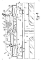
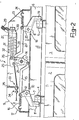
- a safety device 1 for a two-wing inward rototranslation door the door wings being only partly visible and designated 2 and 3.
- Each of the door wings 2 and 3 has a respective top-mounted peg 4 and 5 which is guided slidingly in a single straight track 6 overlying the door wings 2 and 3.
- the safety device 1 comprises two checking levers 7 and 8, one for each peg 4 and 5 for which the levers are designed to form checking members.
- the lever 7 is journalled to a plate 9 (fast with the track 6) at the location of the peg 4 with the wing 2 closed, and is movable through an opening 10 in the track 6 between a home position (see Figure 1) whereat it does not interfere with the peg 4, an,d an operative position (see Figure 2) whereat it holds back the peg 4 by means of a concave arm 11.
- An arm 12 of the lever 7 opposed from the arm 11 is connected to an arm 13 of a lay lever 14 (journalled to the plate 9) by a rod 15 which is journalled to both the arm 12 and the arm 13.
- a spring 16 is stretched between the arm 12 and a ring 17 attached to the plate 9 on the opposed side from the rod 15.
- the lever 8 is journalled to the plate 9 at the location of the peg 5 with the door wing 3 closed, and is movable through an opening 18 in the track 6 between a home position (see Figure 1) and an operative position (see Figure 2) whereat it holds back the peg 5 by means of an arm 19.
- An arm 20 of the lever 8, lying opposedly from the arm 19, is connected to an arm 21 of the lay lever 14, lying opposedly from the arm 13, through a rod 22 journalled to both the arm 20 and the arm 21.
- a spring 23 is stretched between the arm 20 and a ring 24 attached to the plate 9, on the opposed side from the rod 22.
- levers 7 and 8 are interconnected to be both at all times at either their home or operative positions.
- the lay lever 14 is made rotatively rigid with a third arm 25 to which there is connected a rod 26 of a piston 27 arranged to slide sealingly within a cylinder 28 which is permanently supplied with pressurized air through a pipe 29, only partly shown and being connected to a head 30 of the cylinder 28; a spring 31 fits in the cylinder 28 around the rod 26 and is compressed between the piston 27 and a bottom 32 of the cylinder 28.
- the arm 25 is also connected, at the remote side from the piston rod 26, to a cable 33 of the so-called Bowden type having an adjustment assembly 34 mounted on a plate 35 fast with the plate 9 and an operating handle (not shown) mounted at an accessible location from the vehicle inside.
- the safety device 1 operates as follows.
- the device 1 In normal conditions, that is with the pneumatic system supplying compressed air at the set pressure level, the device 1 is at its home position, shown in Figure 1. In this situation, the compressed air will exert in the cylinder 28 a thrust force effective to overcome the elastic bias of the spring 31 and the springs 16 and 23 (by compressing the former and tensioning the latter).
- the various arms, levers, and rods take the positions of Figure 1; more specifically, the arms 11 and 19 of the checking levers 7 and 8 are raised and do not interfere with the pegs 4 and 5 in the track 6.
- FIG. 3 Shown in Figure 3 is a simplified variation of the invention which is only suitable for use with a single door wing instead of two.
- a safety device 101 is shown for a wing 102 of an inward rototranslation door having a peg 103 guided slidingly in a straight track 104.
- the device 101 comprises a checking lever 105 journalled to a plate 106 (fast with the track 104) at the location of the peg 103 with the wing 102 closed; the lever 105 is movable, through an opening 107 in the track 104, between a home position whereat it does not interfere with the peg 103, and an operative position (see Figure 3) whereat it holds back the peg 103 by a concave arm 108.
- An arm 109 of the lever 105 lying opposedly from the arm 108, is connected to a rod 110 of a piston 111 sealingly slidable within a cylinder 112 which is permanently supplied with pressurized air through a pipe 113 connected to a head 114 of the cylinder 112; a spring 115 fits in the cylinder 112 around the piston rod 110 and is compressed between the piston 111 and a bottom 116 of the cylinder 112.
- the arm 109 is also connected, on the opposed side from the rod 110, to a Bowden cable 117 having an adjustment assembly 118 mounted on a small plate 119 fast with the plate 106 and an operating handle (not shown) mounted at an accessible location from the vehicle inside.
- a further spring 120 is compressed between the arm 109 and the small plate 119, being coiled around the cable 117.
- the operation of the safety device 101 is quite similar to that of the device 1, and accordingly, will not be discussed in detail.
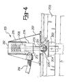
- FIG. 4 a safety device 201 for a wing (not shown) of an inward rototranslation door having a peg 202 which is guided slidingly in a track 203.
- the device 201 comprises a washer 204 which is attached to the peg 202 and formed with an elevation 205.
- the device 201 further comprises a cylinder 206 mounted on a plate 207 (fast with the track 203) at the location of the peg 202 with the door wing closed.
- the cylinder 206 is mounted in a substantially orthogonal position to the track 203, and accommodates a piston 208 slidably in sealed relationship therein which has a piston rod 209 carrying at its free end a small wheel 210 projecting into the track 203 through an opening 211.
- the cylinder 206 is of a type having a closed head 212 and a sealed bottom 213 through which there opens a compressed air supply pipe 214; a spring 215 is compressed between the piston 208 and the head 212.
- the piston rod 209 with the wheel 210 forms a c homeing member for the peg 202 and is movable between a home position whereat it does not interfere with the peg 202 and an operating position (see Figure 4) whereat it holds back the peg 202 by virtue of the wheel 210 becoming engaged with the elevation 205 on the washer 204.
- the operation of the device 201 is similar to that of the devices 1 and 101.
- the peg 202 holding action is provided by the piston rod 209, small wheel 210, and elevation 205 on the washer 204.
- the locked door may be opened by forcing it in its normal opening direction, that is by having the wheel 210 move over and past the elevation 205 and compressing the spring 215.
- a safety device 301 for a door wing (not shown) of an inward rototranslation door having a peg 302 guided slidingly in a track 303 is provided.
- the device 301 comprises a washer 304 which is attached to the peg 302 and has a top surface including a flat sunk portion 305 and a flat raised portion 306 which are interconnected by an obliquely lying portion 307.
- the device 301 also comprises a cylinder 308 mounted on a bracket 309 which is associated adjustably with a plate 310 made fast with the track 303; the bracket 309 is attached to the plate 310 by means of a pin 311 and a bolt 312 passed through a slot in the bracket 309.
- the cylinder 308 accommodates, in sealed sliding relationship therein, a piston 314 having a piston rod 315 jutting into the track 303 through an opening 316 located at the same location as the peg 302 with the door wing closed.
- the cylinder 308 is of a type which has a closed head 317 and a sealed bottom 318 through which there opens a compressed air supply pipe 319; a spring 320 is compressed between the piston 314 and the head 317.
- the piston rod 315 forms a checking member for the peg 302 and is movable between a home position whereat it does not interfere with the peg 302 and an operating position (see Figure 5) whereat it will hold the peg 302 back by engaging with the oblique portion 307 of the washer 304.
- the safety device 301 operates in quite a similar manner to that of the device 201, with the difference that, in the absence of a wheel on the piston rod, provision is made for adjusting the inclined setting of the cylinder 308 during the assembling step of the device 301 in order to ensure best engagement of the piston rod 315 with the washer 304.
- a safety device can fully achieve its set objective: in fact, the reliability of such a device would be ensured by both its simple mechanics and the fact that it is only activated where required and not each time that the door is closed.
- this safety device goes a step further than lawful provisions by enabling (in a simple way) a door locked because of a compressed air outage to be opened in emergency situations.
Landscapes
- Power-Operated Mechanisms For Wings (AREA)
Applications Claiming Priority (2)
| Application Number | Priority Date | Filing Date | Title |
|---|---|---|---|
| IT21423/86A IT1198019B (it) | 1986-08-06 | 1986-08-06 | Dispositivo di sicurezza per una porta di un mezzo di trasproto pubblico |
| IT2142386 | 1986-08-06 |
Publications (2)
| Publication Number | Publication Date |
|---|---|
| EP0255991A2 true EP0255991A2 (fr) | 1988-02-17 |
| EP0255991A3 EP0255991A3 (fr) | 1988-04-06 |
Family
ID=11181556
Family Applications (1)
| Application Number | Title | Priority Date | Filing Date |
|---|---|---|---|
| EP87830190A Withdrawn EP0255991A3 (fr) | 1986-08-06 | 1987-05-26 | Dispositif de sécurité pour portes de moyens de transport public |
Country Status (2)
| Country | Link |
|---|---|
| EP (1) | EP0255991A3 (fr) |
| IT (1) | IT1198019B (fr) |
Cited By (7)
| Publication number | Priority date | Publication date | Assignee | Title |
|---|---|---|---|---|
| EP0838425A1 (fr) * | 1996-10-25 | 1998-04-29 | C. HAUSHAHN GmbH & Co. | Dispositif d'ouverture d'urgence pour portes d'ascenseur |
| ES2114450A1 (es) * | 1995-09-13 | 1998-05-16 | Faiveley Espanola | Mecanismo electrico de bloqueo-activacion para puertas. |
| US20180347249A1 (en) * | 2017-05-31 | 2018-12-06 | Westinghouse Air Brake Technologies Corporation | Rail transit door isolation lock |
| US20190376322A1 (en) * | 2017-05-31 | 2019-12-12 | Westinghouse Air Brake Technologies Corporation | Lock mechanism and door assembly |
| US10724278B2 (en) | 2018-02-09 | 2020-07-28 | Westinghouse Air Brake Technologies Corporation | Secondary retention device for bi-parting doors |
| US10994752B2 (en) | 2016-04-06 | 2021-05-04 | Westinghouse Air Brake Technologies Corporation | Lock mechanism for improved door panel seal |
| US20220145676A1 (en) * | 2020-11-06 | 2022-05-12 | Westinghouse Air Brake Technologies Corporation | Integrated primary lock and isolation lock emergency release mechanism |
Family Cites Families (2)
| Publication number | Priority date | Publication date | Assignee | Title |
|---|---|---|---|---|
| DE1811400C3 (de) * | 1968-11-28 | 1974-03-07 | Wegmann & Co, 3500 Kassel | Vorrichtung für mehrflügelige Türen, insbesondere für Türen mit zwei Schwenkflügeln |
| DE8517249U1 (de) * | 1985-06-13 | 1985-09-12 | Gebr. Bode & Co GmbH, 3500 Kassel | Fahrzeugtür |
-
1986
- 1986-08-06 IT IT21423/86A patent/IT1198019B/it active
-
1987
- 1987-05-26 EP EP87830190A patent/EP0255991A3/fr not_active Withdrawn
Cited By (9)
| Publication number | Priority date | Publication date | Assignee | Title |
|---|---|---|---|---|
| ES2114450A1 (es) * | 1995-09-13 | 1998-05-16 | Faiveley Espanola | Mecanismo electrico de bloqueo-activacion para puertas. |
| EP0838425A1 (fr) * | 1996-10-25 | 1998-04-29 | C. HAUSHAHN GmbH & Co. | Dispositif d'ouverture d'urgence pour portes d'ascenseur |
| US10994752B2 (en) | 2016-04-06 | 2021-05-04 | Westinghouse Air Brake Technologies Corporation | Lock mechanism for improved door panel seal |
| US20180347249A1 (en) * | 2017-05-31 | 2018-12-06 | Westinghouse Air Brake Technologies Corporation | Rail transit door isolation lock |
| US20190376322A1 (en) * | 2017-05-31 | 2019-12-12 | Westinghouse Air Brake Technologies Corporation | Lock mechanism and door assembly |
| US11767689B2 (en) * | 2017-05-31 | 2023-09-26 | Westinghouse Air Brake Technologies Corporation | Lock mechanism and door assembly |
| US10724278B2 (en) | 2018-02-09 | 2020-07-28 | Westinghouse Air Brake Technologies Corporation | Secondary retention device for bi-parting doors |
| US20220145676A1 (en) * | 2020-11-06 | 2022-05-12 | Westinghouse Air Brake Technologies Corporation | Integrated primary lock and isolation lock emergency release mechanism |
| US12264513B2 (en) * | 2020-11-06 | 2025-04-01 | Westinghouse Air Brake Technologies Corporation | Integrated primary lock and isolation lock emergency release mechanism |
Also Published As
| Publication number | Publication date |
|---|---|
| IT8621423A0 (it) | 1986-08-06 |
| EP0255991A3 (fr) | 1988-04-06 |
| IT8621423A1 (it) | 1988-02-06 |
| IT1198019B (it) | 1988-12-21 |
Similar Documents
| Publication | Publication Date | Title |
|---|---|---|
| US5337977A (en) | Vent-latch interlock assembly for an aircraft door | |
| US6139073A (en) | Lock assembly | |
| US4884831A (en) | Auxiliary door lock for a powered garage door | |
| US4875722A (en) | Exit device actuator and dogger | |
| US7360803B2 (en) | Lock assembly | |
| US5676003A (en) | Blocking device for a motor vehicle door | |
| US4801163A (en) | Exit device actuator and dogger | |
| US4157844A (en) | Tailgate lock and control assembly | |
| JPH01294190A (ja) | エレベータ用のロック機構付きドア駆動装置 | |
| US6641183B2 (en) | Door latch device | |
| US20070214724A1 (en) | Unlock mechanism for a rotary door operator | |
| US5522626A (en) | Lock with assisted closure especially for a motor vehicle door | |
| US5253906A (en) | Linkage for vehicle door latch | |
| EP0255991A2 (fr) | Dispositif de sécurité pour portes de moyens de transport public | |
| CN116238681B (zh) | 一种舱门上位锁机构装置 | |
| GB2047328A (en) | Operating barrier gates | |
| GB2135759A (en) | Valve closing device | |
| EP0651848B1 (fr) | Dispositifs de fermeture de porte | |
| DK172426B1 (da) | Vindue med en paskvillåsemekanisme og en vinduesoperator med et udstillerelement | |
| GB2317201A (en) | Linkage for up-and-over automatic door lock mechanism | |
| US6948765B2 (en) | Lock mechanism for a rotary door operator | |
| US2998992A (en) | Mechanism for pulling a lock handle into a vehicle door | |
| EP0590128B1 (fr) | Mecanisme pour verrouiller un arbre rotatif | |
| NO813657L (no) | Doersperre, saerlig for kjoeretoey | |
| US4035954A (en) | Garage door assemblies |
Legal Events
| Date | Code | Title | Description |
|---|---|---|---|
| PUAI | Public reference made under article 153(3) epc to a published international application that has entered the european phase |
Free format text: ORIGINAL CODE: 0009012 |
|
| PUAL | Search report despatched |
Free format text: ORIGINAL CODE: 0009013 |
|
| AK | Designated contracting states |
Kind code of ref document: A2 Designated state(s): AT BE CH DE ES FR GB GR LI LU NL SE |
|
| AK | Designated contracting states |
Kind code of ref document: A3 Designated state(s): AT BE CH DE ES FR GB GR LI LU NL SE |
|
| STAA | Information on the status of an ep patent application or granted ep patent |
Free format text: STATUS: THE APPLICATION IS DEEMED TO BE WITHDRAWN |
|
| 18D | Application deemed to be withdrawn |
Effective date: 19881007 |
|
| RIN1 | Information on inventor provided before grant (corrected) |
Inventor name: SESSA, MASSIMO |