EP0256257A2 - Dispositif de frisage à boîte de bourrage pour le frisage de câbles de filaments synthétiques - Google Patents
Dispositif de frisage à boîte de bourrage pour le frisage de câbles de filaments synthétiques Download PDFInfo
- Publication number
- EP0256257A2 EP0256257A2 EP87109068A EP87109068A EP0256257A2 EP 0256257 A2 EP0256257 A2 EP 0256257A2 EP 87109068 A EP87109068 A EP 87109068A EP 87109068 A EP87109068 A EP 87109068A EP 0256257 A2 EP0256257 A2 EP 0256257A2
- Authority
- EP
- European Patent Office
- Prior art keywords
- pressure
- end faces
- thrust washer
- deflection
- pressing
- Prior art date
- Legal status (The legal status is an assumption and is not a legal conclusion. Google has not performed a legal analysis and makes no representation as to the accuracy of the status listed.)
- Granted
Links
Images

Classifications
-
- D—TEXTILES; PAPER
- D02—YARNS; MECHANICAL FINISHING OF YARNS OR ROPES; WARPING OR BEAMING
- D02G—CRIMPING OR CURLING FIBRES, FILAMENTS, THREADS, OR YARNS; YARNS OR THREADS
- D02G1/00—Producing crimped or curled fibres, filaments, yarns, or threads, giving them latent characteristics
- D02G1/12—Producing crimped or curled fibres, filaments, yarns, or threads, giving them latent characteristics using stuffer boxes
- D02G1/125—Producing crimped or curled fibres, filaments, yarns, or threads, giving them latent characteristics using stuffer boxes including means for monitoring or controlling yarn processing
Definitions
- the invention is based on a device as described in DE-OS 24 03 970.
- a stuffer box crimping device is generally known and consists of the features of the preamble of the claim.
- the problem with such a device for crimping smoothly spun man-made fibers, which already works in practice, is, according to Wei, the sealing of the press roll nip in the region of the end faces of the press rolls.
- the nip of the press roll is sealed at both ends by a thrust washer, which abuts against the end faces of the two press rolls.
- the thrust washers must rest under pressure on the end faces of the press rolls. However, this causes greater abrasion, which results in more frequent replacement of the thrust washers.
- this problem is eliminated in that the pressure plate is held at a minimum, predetermined distance on the end faces of the press rolls, by means of a sensing element, the actual distance between the end faces of the press rolls and the respective pressure plate is measured and then the target distance is readjusted.
- the readjustment of the pressure plate is carried out discontinuously, namely in that the pressure plate is pressed against the two end faces of the two associated press rolls and then then moves back by a small, adjustable my distance. It has been found that this type of adjustment of the thrust washer is disadvantageous insofar as fine and very fine fibers are pushed into the my-spacing and thus lead to the failure of the device overall lead. It should be noted that with certain fibers the pressure disks must be pressed against the end faces of the press rolls in any case in order to achieve a sufficient seal of the press roll nip.
- the invention has for its object to take measures with which the arrangement of the thrust washers to the end faces of the press rolls can always be kept optimal, without on the one hand to get too much abrasion and on the other hand to create no gap, however small, in which the fibers can undesirably slide.
- the sensing element is designed as an instrument for determining a deflection of a support of the pressure plate which arises due to the pressing pressure, and the pressing pressure can be regulated as a function of the continuously detected deflection of the support, such as the side window.
- the invention is therefore based on the knowledge that, when generating a compressive pressure sufficient for sealing, the support of the thrust washer is possibly also subjected to a certain deflection. If the extent of this deflection is now determined using sensitive measuring instruments, this value can be used to adjust the pressing pressure. With the aid of the device according to the invention, the actual contact pressure can thus be determined continuously as a function of the deflection of the carrier and the abrasion can thus be kept constant in a still permissible minimum value. With the device according to the invention it is ensured that even with changes in temperature or other varying conditions on the machine, which result in the changes between the pressure plate and the roll end faces, the contact pressure of the pressure plates on the roll end faces always remains constant and thus an adequate seal is guaranteed.
- a unit is to be provided, to which an arbitrary setpoint of permissible deflection can be entered. If, in the course of the operation of the device, after the adjustment in the warm state, an actual value arises which differs in comparison with the entered target value, the regulation for changing the contact pressure takes effect.
- the setpoint can be any value, it can extend from zero to a value at which there is considerable wear on the thrust washer, but also an extremely good seal would be achieved.
- the instrument in the device according to the invention, it is advantageous to design the instrument as a pressure cell.
- the load cell now does not measure a change in the distance between the side windows from the end faces of the feed rollers in a fine distance measurement, but rather the new pressure which arises due to the changing distance between the pressure disc and the end faces of the feed rollers.
- Such an electronically controlled load cell can measure the change in distance or the deflection of the support of the pressure plate more sensitively and regulate the control of the distance of the pressure plate based on the measurement pulses.
- the invention therefore provides for the contact surface of the pressure plate to be spatially curved, preferably crowned. If the counter surface is machined accordingly, a parallel arrangement of the thrust washer to the end faces can now be ensured even if the side disk changes in size in relation to the end faces of the feed rollers.
- a stuffer box crimping device consists of the two feed rollers 1 and 2 and the chamber plates 4 and 5 adjoining the press roller nip 6, which form the chamber space 3 between them.
- the upper chamber plate 5 is arranged such that it can be pivoted downwards (shown in broken lines).
- the lateral area of the chamber space is closed by the two side plates 7 and 8 shown in FIG. 2.
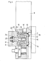
- a pressure or wear plate 9, 10 are held at the level of the press nip 6, each with pressing pressure 11, 12 are pressed against the end face of the feed rollers 1, 2. Because of this pressure, the supports - here the side plates 7, 8 - bend in the direction of the parts shown in FIG. 3. The amount of bending or torsion of the side plates can be measured and used as a measure of the actual friction between the thrust washer and the end faces of the rolls.
- the pressure plate 10 is installed in the side window 8.
- the thrust washer 10 has two surfaces.
- the wear surface is assigned to the end faces 13 of the pair of intake rollers 1, 2.
- the back surface - here called the pressing surface 14 - is spatially curved, if not to say crowned.
- the spherical surface is worked into the pressure plate, while the corresponding adjusting device, designated overall by 15, for adjusting the pressure plate in the area of the pressure surface 14 is convexly shaped.
- the pressure plate 10 can always align parallel to the end faces 13 of the feed rollers 1, 2 in accordance with the torturing or bending of the side window 8.
- the construction of the adjusting device 15 is of no particular importance here. It consists of an outer toothed ring 16, which is provided with pins 17 on its end face, in order to transmit the rotation of the toothed ring to the thrust washer for its even wear.
- the toothed ring 16 is mounted on an adjusting ring 19 via ball bearings 18.
- the adjusting ring 19 also has end teeth 20 on its outer circumference, into which the drive gear 21 engages.
- an internal thread is incorporated, which engages in a corresponding external thread of an adjusting bolt 22.
- the adjusting bolt 22 is longitudinally displaceable but secured against rotation in a part 8 ⁇ of the side window 8.
- a pressure cell 23 is arranged in a further part 8 'of the side window 8.
- the contact of the pressure cell to the adjusting bolt 22 is ensured by a bearing 24, which is also spherical with a corresponding counter surface.
- the operation of this device is as follows:
- the drive of the thrust washer for uniform rotation takes place via the gear 16 ⁇ , which engages in the end teeth of the toothed ring 16.
- the distance adjustment of the thrust washer takes place via the toothed wheel 21, which engages with its toothing in the toothing of the adjusting ring 19 and, due to the thread in the adjusting bolt 22, causes a spacing adjustment of the thrust washer 10 in relation to the end face of the feed roller 1.
- the distance between the thrust washer 10 and the end face 13 of the feed roller 1 is transmitted via the toothed ring 16, then via the ball bearing 18, the adjusting ring 19 to the adjusting bolt 22, which in turn transmits this existing distance to the pressure cell 23.
- An electronic pulse from electrical units which are not shown in detail in the drawing, drives the gearwheel 21, which presses the pressure plate 10 against the end face 13 of the feed rollers 1, 2 as a function of the continuously detected deflection of the carrier - here the side window 8 - regulates and keeps constant.
Landscapes
- Engineering & Computer Science (AREA)
- Mechanical Engineering (AREA)
- Textile Engineering (AREA)
- Yarns And Mechanical Finishing Of Yarns Or Ropes (AREA)
Applications Claiming Priority (4)
| Application Number | Priority Date | Filing Date | Title |
|---|---|---|---|
| DE19863621479 DE3621479A1 (de) | 1986-06-26 | 1986-06-26 | Stauchkammerkraeuselvorrichtung zum kraeuseln von synthetischen fadenscharen |
| DE3621479 | 1986-06-26 | ||
| DE19863626522 DE3626522A1 (de) | 1986-06-26 | 1986-08-05 | Stauchkammerkraeuselvorrichtung zum kraeuseln synthetischer fadenscharen |
| DE3626522 | 1986-08-05 |
Publications (3)
| Publication Number | Publication Date |
|---|---|
| EP0256257A2 true EP0256257A2 (fr) | 1988-02-24 |
| EP0256257A3 EP0256257A3 (en) | 1990-02-28 |
| EP0256257B1 EP0256257B1 (fr) | 1992-12-02 |
Family
ID=25845009
Family Applications (1)
| Application Number | Title | Priority Date | Filing Date |
|---|---|---|---|
| EP87109068A Expired - Lifetime EP0256257B1 (fr) | 1986-06-26 | 1987-06-24 | Dispositif de frisage à boîte de bourrage pour le frisage de câbles de filaments synthétiques |
Country Status (3)
| Country | Link |
|---|---|
| US (1) | US4807337A (fr) |
| EP (1) | EP0256257B1 (fr) |
| DE (2) | DE3626522A1 (fr) |
Cited By (2)
| Publication number | Priority date | Publication date | Assignee | Title |
|---|---|---|---|---|
| DE29618617U1 (de) * | 1996-10-25 | 1998-02-26 | Neumag - Neumünstersche Maschinen- und Anlagenbau GmbH, 24536 Neumünster | Vorrichtung zum Kräuseln von synthetischen Fadenbündeln oder -bändern |
| US6088891A (en) * | 1996-10-25 | 2000-07-18 | Neumag - Neumuenstersche Maschinen - Und Anlagenbau Gmbh | Device for crimping synthetic thread bundles or strips |
Families Citing this family (9)
| Publication number | Priority date | Publication date | Assignee | Title |
|---|---|---|---|---|
| DE19537958C1 (de) * | 1995-10-12 | 1996-11-14 | Neumag Gmbh | Vorrichtung zum Kräuseln von synthetischen Fadenbündeln oder -bändern |
| DE19538423C2 (de) * | 1995-10-16 | 1997-08-21 | Neumag Gmbh | Vorrichtung zum Kräuseln von synthetischen Fadenbündeln oder -bändern |
| US6351877B1 (en) | 2000-05-31 | 2002-03-05 | Eastman Chemical Company | Synthetic fiber crimper, method of crimping and crimped fiber produced therefrom |
| EP1512779A1 (fr) * | 2003-08-28 | 2005-03-09 | Power-heat-set GmbH | Dispositif et procédé pour le traitement de matériaux allongés |
| EP2098622B1 (fr) * | 2008-03-03 | 2011-03-23 | M.A.E. S.p.A. | Dispositif pour friser des filaments de fibres synthétiques et méthodes de contrôle |
| CN102828293B (zh) * | 2011-06-16 | 2015-05-20 | 南通醋酸纤维有限公司 | 填塞箱卷曲机耐磨夹板装置 |
| CN102828294B (zh) * | 2011-06-16 | 2015-04-15 | 南通醋酸纤维有限公司 | 填塞箱卷曲机耐磨夹板装置 |
| DE112016001061A5 (de) * | 2015-03-06 | 2018-01-04 | Oerlikon Textile Gmbh & Co. Kg | Vorrichtung zum Kräuseln eines Tows |
| EP3891324B1 (fr) * | 2018-12-04 | 2024-12-04 | Oerlikon Textile GmbH & Co. KG | Procédé de fonctionnement d'un dispositif de frisage et dispositif de frisage |
Family Cites Families (9)
| Publication number | Priority date | Publication date | Assignee | Title |
|---|---|---|---|---|
| CS152773B1 (fr) * | 1968-02-24 | 1974-02-22 | ||
| US3618183A (en) * | 1970-02-11 | 1971-11-09 | Monsanto Co | Insert pressure controller |
| CH529856A (de) * | 1970-08-10 | 1972-10-31 | Vepa Ag | Vorrichtung zum Kräuseln synthetischer Fadenscharen |
| GB1571521A (en) * | 1976-11-25 | 1980-07-16 | Vepa Ag | Apparatus for crimping synthetic yarns and the like |
| US4115908A (en) * | 1978-02-06 | 1978-09-26 | Eastman Kodak Company | Apparatus for stuffer box crimping |
| DE3326589C2 (de) * | 1983-07-23 | 1994-02-24 | Fleissner Maschf Ag | Vorrichtung zum Kräuseln synthetischer Fadenscharen |
| US4521944A (en) * | 1984-01-23 | 1985-06-11 | Eastman Kodak Company | Dowel-aligned multiple plate stuffer box crimper construction for filter tow |
| DE3421480A1 (de) * | 1984-06-08 | 1985-12-12 | Conradty GmbH & Co Metallelektroden KG, 8505 Röthenbach | Beschichtete ventilmetall-elektrode zur elektrolytischen galvanisierung |
| JPH05140458A (ja) * | 1991-11-20 | 1993-06-08 | Toray Dow Corning Silicone Co Ltd | 湿気硬化型シリコーン粘着剤組成物 |
-
1986
- 1986-08-05 DE DE19863626522 patent/DE3626522A1/de not_active Withdrawn
-
1987
- 1987-06-24 DE DE8787109068T patent/DE3782881D1/de not_active Expired - Fee Related
- 1987-06-24 EP EP87109068A patent/EP0256257B1/fr not_active Expired - Lifetime
- 1987-06-26 US US07/066,533 patent/US4807337A/en not_active Expired - Fee Related
Cited By (2)
| Publication number | Priority date | Publication date | Assignee | Title |
|---|---|---|---|---|
| DE29618617U1 (de) * | 1996-10-25 | 1998-02-26 | Neumag - Neumünstersche Maschinen- und Anlagenbau GmbH, 24536 Neumünster | Vorrichtung zum Kräuseln von synthetischen Fadenbündeln oder -bändern |
| US6088891A (en) * | 1996-10-25 | 2000-07-18 | Neumag - Neumuenstersche Maschinen - Und Anlagenbau Gmbh | Device for crimping synthetic thread bundles or strips |
Also Published As
| Publication number | Publication date |
|---|---|
| US4807337A (en) | 1989-02-28 |
| DE3782881D1 (de) | 1993-01-14 |
| EP0256257B1 (fr) | 1992-12-02 |
| DE3626522A1 (de) | 1988-02-11 |
| EP0256257A3 (en) | 1990-02-28 |
Similar Documents
| Publication | Publication Date | Title |
|---|---|---|
| EP0201783B1 (fr) | Système de rouleau à compensation de la flèche et réglage de la température | |
| EP0256257B1 (fr) | Dispositif de frisage à boîte de bourrage pour le frisage de câbles de filaments synthétiques | |
| DE2813719C2 (de) | Vorrichtung zum Messen der Planheit von Metallbändern | |
| DE3325385A1 (de) | Druckbehandlungswalze | |
| EP0478734B1 (fr) | Dispositif de mesure | |
| DE2543738C3 (de) | Kalander für Folien aus thermoplastischem Kunststoff oder elastomerem Material | |
| CH619177A5 (fr) | ||
| DE3728313C2 (fr) | ||
| DE3020669C2 (de) | Verfahren zur Steuerung der Liniendruckverteilung in einem Kalander sowie ensprechender Kalander | |
| DE2729559C2 (de) | Presse zum Herstellen von Werkstoffplatten o.dgl | |
| DE3115461A1 (de) | "regelanordnung an band- oder blechwalzwerken" | |
| DE3516779C2 (fr) | ||
| DE69223531T2 (de) | Verfahren zur zerstörungsfreien on-line-Messung einer Charakteristik eines kontinuierlich hergestellten Produktes und entsprechende Vorrichtung | |
| EP0476407B1 (fr) | Appareil pour le guidage d'un chapeau d'une machine de cardage pour le coton ou pour la laine | |
| EP0460442B1 (fr) | Dispositif de mesure de l'épaisseur et/ou de l'inégalite de rubans de fibres | |
| EP0072504A2 (fr) | Broyeur à cylindres pour le broyage de matières fluides | |
| DE3300251C2 (fr) | ||
| DE3621479A1 (de) | Stauchkammerkraeuselvorrichtung zum kraeuseln von synthetischen fadenscharen | |
| AT414245B (de) | Verfahren zum beschichten in einem filmtransferbeschichter und anordnung für einen filmtransferbeschichter | |
| DE4429455A1 (de) | Verfahren zum Verdichten einer Papierbahn und Preßwerk zur Durchführung des Verfahrens | |
| EP0435411B1 (fr) | Calandre à cylindres de fusion avec au moins deux rouleaux | |
| DE2403970C2 (de) | Vorrichtung zum Kräuseln synthetischer Fadenscharen | |
| DE4231743A1 (de) | Vorrichtung zum Auftragen von Substanzen auf ein Substrat | |
| DE3533210C2 (fr) | ||
| DE2117393C3 (de) | Vorrichtung zum Kräuseln synthetischer Fadenscharen |
Legal Events
| Date | Code | Title | Description |
|---|---|---|---|
| PUAI | Public reference made under article 153(3) epc to a published international application that has entered the european phase |
Free format text: ORIGINAL CODE: 0009012 |
|
| AK | Designated contracting states |
Kind code of ref document: A2 Designated state(s): DE FR GB IT NL |
|
| PUAL | Search report despatched |
Free format text: ORIGINAL CODE: 0009013 |
|
| AK | Designated contracting states |
Kind code of ref document: A3 Designated state(s): DE FR GB IT NL |
|
| 17P | Request for examination filed |
Effective date: 19900216 |
|
| 17Q | First examination report despatched |
Effective date: 19920204 |
|
| GRAA | (expected) grant |
Free format text: ORIGINAL CODE: 0009210 |
|
| AK | Designated contracting states |
Kind code of ref document: B1 Designated state(s): DE FR GB IT NL |
|
| PG25 | Lapsed in a contracting state [announced via postgrant information from national office to epo] |
Ref country code: IT Free format text: LAPSE BECAUSE OF FAILURE TO SUBMIT A TRANSLATION OF THE DESCRIPTION OR TO PAY THE FEE WITHIN THE PRE;WARNING: LAPSES OF ITALIAN PATENTS WITH EFFECTIVE DATE BEFORE 2007 MAY HAVE OCCURRED AT ANY TIME BEFORE 2007. THE CORRECT EFFECTIVE DATE MAY BE DIFFERENT FROM THE ONE RECORDED.SCRIBED TIME-LIMIT Effective date: 19921202 Ref country code: FR Effective date: 19921202 Ref country code: GB Effective date: 19921202 Ref country code: NL Effective date: 19921202 |
|
| REF | Corresponds to: |
Ref document number: 3782881 Country of ref document: DE Date of ref document: 19930114 |
|
| EN | Fr: translation not filed | ||
| NLV1 | Nl: lapsed or annulled due to failure to fulfill the requirements of art. 29p and 29m of the patents act | ||
| GBV | Gb: ep patent (uk) treated as always having been void in accordance with gb section 77(7)/1977 [no translation filed] |
Effective date: 19921202 |
|
| PLBE | No opposition filed within time limit |
Free format text: ORIGINAL CODE: 0009261 |
|
| STAA | Information on the status of an ep patent application or granted ep patent |
Free format text: STATUS: NO OPPOSITION FILED WITHIN TIME LIMIT |
|
| 26N | No opposition filed | ||
| PGFP | Annual fee paid to national office [announced via postgrant information from national office to epo] |
Ref country code: DE Payment date: 19950403 Year of fee payment: 9 |
|
| PG25 | Lapsed in a contracting state [announced via postgrant information from national office to epo] |
Ref country code: DE Effective date: 19970301 |