EP0256334A1 - Schiefscheibenverdichter mit Vorrichtung zur Hubveränderung - Google Patents
Schiefscheibenverdichter mit Vorrichtung zur Hubveränderung Download PDFInfo
- Publication number
- EP0256334A1 EP0256334A1 EP87110523A EP87110523A EP0256334A1 EP 0256334 A1 EP0256334 A1 EP 0256334A1 EP 87110523 A EP87110523 A EP 87110523A EP 87110523 A EP87110523 A EP 87110523A EP 0256334 A1 EP0256334 A1 EP 0256334A1
- Authority
- EP
- European Patent Office
- Prior art keywords
- control means
- wobble plate
- plate type
- passageway
- valve control
- Prior art date
- Legal status (The legal status is an assumption and is not a legal conclusion. Google has not performed a legal analysis and makes no representation as to the accuracy of the status listed.)
- Granted
Links
Images


Classifications
-
- F—MECHANICAL ENGINEERING; LIGHTING; HEATING; WEAPONS; BLASTING
- F04—POSITIVE - DISPLACEMENT MACHINES FOR LIQUIDS; PUMPS FOR LIQUIDS OR ELASTIC FLUIDS
- F04B—POSITIVE-DISPLACEMENT MACHINES FOR LIQUIDS; PUMPS
- F04B13/00—Pumps specially modified to deliver fixed or variable measured quantities
-
- F—MECHANICAL ENGINEERING; LIGHTING; HEATING; WEAPONS; BLASTING
- F04—POSITIVE - DISPLACEMENT MACHINES FOR LIQUIDS; PUMPS FOR LIQUIDS OR ELASTIC FLUIDS
- F04B—POSITIVE-DISPLACEMENT MACHINES FOR LIQUIDS; PUMPS
- F04B27/00—Multi-cylinder pumps specially adapted for elastic fluids and characterised by number or arrangement of cylinders
- F04B27/08—Multi-cylinder pumps specially adapted for elastic fluids and characterised by number or arrangement of cylinders having cylinders coaxial with, or parallel or inclined to, main shaft axis
- F04B27/14—Control
- F04B27/16—Control of pumps with stationary cylinders
- F04B27/18—Control of pumps with stationary cylinders by varying the relative positions of a swash plate and a cylinder block
- F04B27/1804—Controlled by crankcase pressure
- F04B2027/1809—Controlled pressure
- F04B2027/1813—Crankcase pressure
-
- F—MECHANICAL ENGINEERING; LIGHTING; HEATING; WEAPONS; BLASTING
- F04—POSITIVE - DISPLACEMENT MACHINES FOR LIQUIDS; PUMPS FOR LIQUIDS OR ELASTIC FLUIDS
- F04B—POSITIVE-DISPLACEMENT MACHINES FOR LIQUIDS; PUMPS
- F04B27/00—Multi-cylinder pumps specially adapted for elastic fluids and characterised by number or arrangement of cylinders
- F04B27/08—Multi-cylinder pumps specially adapted for elastic fluids and characterised by number or arrangement of cylinders having cylinders coaxial with, or parallel or inclined to, main shaft axis
- F04B27/14—Control
- F04B27/16—Control of pumps with stationary cylinders
- F04B27/18—Control of pumps with stationary cylinders by varying the relative positions of a swash plate and a cylinder block
- F04B27/1804—Controlled by crankcase pressure
- F04B2027/1822—Valve-controlled fluid connection
- F04B2027/1831—Valve-controlled fluid connection between crankcase and suction chamber
-
- F—MECHANICAL ENGINEERING; LIGHTING; HEATING; WEAPONS; BLASTING
- F04—POSITIVE - DISPLACEMENT MACHINES FOR LIQUIDS; PUMPS FOR LIQUIDS OR ELASTIC FLUIDS
- F04B—POSITIVE-DISPLACEMENT MACHINES FOR LIQUIDS; PUMPS
- F04B27/00—Multi-cylinder pumps specially adapted for elastic fluids and characterised by number or arrangement of cylinders
- F04B27/08—Multi-cylinder pumps specially adapted for elastic fluids and characterised by number or arrangement of cylinders having cylinders coaxial with, or parallel or inclined to, main shaft axis
- F04B27/14—Control
- F04B27/16—Control of pumps with stationary cylinders
- F04B27/18—Control of pumps with stationary cylinders by varying the relative positions of a swash plate and a cylinder block
- F04B27/1804—Controlled by crankcase pressure
- F04B2027/184—Valve controlling parameter
- F04B2027/1854—External parameters
-
- F—MECHANICAL ENGINEERING; LIGHTING; HEATING; WEAPONS; BLASTING
- F04—POSITIVE - DISPLACEMENT MACHINES FOR LIQUIDS; PUMPS FOR LIQUIDS OR ELASTIC FLUIDS
- F04B—POSITIVE-DISPLACEMENT MACHINES FOR LIQUIDS; PUMPS
- F04B27/00—Multi-cylinder pumps specially adapted for elastic fluids and characterised by number or arrangement of cylinders
- F04B27/08—Multi-cylinder pumps specially adapted for elastic fluids and characterised by number or arrangement of cylinders having cylinders coaxial with, or parallel or inclined to, main shaft axis
- F04B27/14—Control
- F04B27/16—Control of pumps with stationary cylinders
- F04B27/18—Control of pumps with stationary cylinders by varying the relative positions of a swash plate and a cylinder block
- F04B27/1804—Controlled by crankcase pressure
- F04B2027/184—Valve controlling parameter
- F04B2027/1859—Suction pressure
Definitions
- This invention relates to a wobble plate type compressor for an automotive air conditioner, and more particularly, to a wobble plate type compressor with a variable capacity mechanism which has an effective characteristic for cooling down.
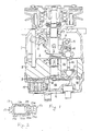
- FIG. 1 the construction of a conventional wobble plate type compressor is shown.
- the compressor includes a compressor housing 1 having a cylinder block 2 which is provided with a plurality of cylinders 22 and a crank chamber 3, and a cylinder head 4 which is mounted on one end portion of cylinder block 2 through a valve plate 5.
- a drive shaft 6 is rotatably supported on a tubular extension 11 which is formed on the other end of the compressor housing 1 through a bearing 7 and, the inner terminal end of the drive shaft 6 is extended within the crank chamber 3 to rotatably support on a central hole 21 of cylinder block 2 through a bearing 8.
- a rotor 9 is fixed on the drive shaft 6 and the end of the rotor 9 is connected to an inclined plate 10 through a hinge mechanism 91, therefore, the inclined plate 10 is driven together with the rotor 9 and hinge mechanism 91 while varying the inclination angle of plate 10.
- the slant surface of the inclined plate 10 is in close proximity to the surface of a wobble plate 12 which is rotatably supported thereon.
- a thrust bearing 13 is disposed between the slant surface of the inclined plate 10 and the wobble plate 12.
- a guide bar 14 is axially extended within the crank chamber 3 so as to connect one end of the compressor housing 1 and cylinder block 2. The lower end portion of wobble plate 12 engages a guide bar 14 to enable wobble plate 12 to reciprocate along guide bar 14 while preventing any rotational motion.
- a plurality of pistons 15 are slidably fitted within a respective cylinder 22 and are connected to wobble plate 12 through connecting rods 16.
- Cylinder head 4 is divided into a suction chamber 41 and a discharge chamber 42.
- Control valve mechanism 17 with a precise structure as shown in Fig. 2 is disposed in a suction chamber 41 and is controlling the opening and closing of the first channel 18 which is connecting the crank chamber 3 with the suction chamber 41.
- Control valve mechanism 17 includes a first casing 171, a second casing 172 which is fixed on one end surface of the first casing 171, and bellows 173 which is disposed within the interior space of the first casing 171 and holding its position by a coil spring 174.
- Bellows 173 is provided with a valve porltion 173a at the outer end surface thereof and a coil spring (not shown) is disposed within bellows 173, to control the expansion and contraction of bellows 173.
- the first casing 171 is provided with an aperture 171a at its outer peripheral portion to communicate the interior of first casing 171 with suction chamber 41.
- the second casing 172 is provided with a second channel 172a communicated with suction chamber 41 through first channel 18 and a third channel 172b which communicates the interior of the first casing 171 with the crank chamber 3 through the first channel 18 and the second channel 172b.
- crank chamber 3 and suction chamber 41 can be connected with one another through the control valve mechanism 17.
- control valve mechanism 17 Operation of the control valve mechanism 17 will be described below. If the pressure in suction chamber 41 exceeds a predetermined value, the bellows 173 in the first casing 171 shrinks and moves valve portion 173a toward left in the drawing. Accordingly, the opening of the third channel 172b is opened, and crank chamber 3 is communicating with suction chamber 41 through first channel 18, second channel 172a and thrid channel 172b. Therefore, the pressure in crank chamber 3, i.e., rear pressure added to pistons 15 is decreased, thus the inclination angle of wobble plate 12 is increased. As a result, the stroke volume of pistons 15 is increased, and the capacity of the compressor is also increased.
- a wobble plate type compressor with a capacity mechanism shall be provided which has an improved characteristic for cooling down.
- a wobble plate type compressor includes a compressor housing having a cylinder block provided with a plurality of cylinders and a crank chamber adjacent the cylinder block.
- a piston is slidably fitted within each of the cylinders and reciprocated by a swash plate driven by a drive mechanism. The stroke of the piston is varied by changes of pressure in the crank chamber.
- a front end plate is mounted on the compressor housing, rotat ably supporting the drive mechanism.
- a rear end plate is mounted on the opposite end of the compressor housing and is dividing its interior space into a suction chamber and a discharge chamber.
- a passageway is formed through the housing to connect the crank chamber and the suction chamber.
- variable capacity control means is disposed on the rear end plate for controlling the opening and closing of the passageway.
- the variable capacity control means includes a first valve control means for controlling movement of a valve element to open and close the passageway in response to changes of refrigerant pressure in the compressor, and second valve control means coupled to the first valve control means and forcedly open the passageway in spite of the movement of the first valve control means.
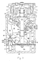
- the compressor includes a front end plate 30, a compressor housing 31 which is provided with a crank chamber 32 and a cylinder block 33, and a cylinder head 34 which is attached on one end surface of the cylinder block 33 through a valve plate 35 by securing belts (not shown).
- a drive shaft 36 is rotatably supported within the front end plate 30 through a bearing 301 at one end thereof and extends into a central aperture 331 of the cylinder block 33.
- the other end of drive shaft 36 is rotatably supported within the cylinder block 33 through a bearing 332 in a central hole 331.
- a rotor 37 is fixedly disposed on the outer terminal end of drive shaft 36 and is connected to an inclined plate 38 through a hinge mechanism 39.
- Inclined plate 38 is axially and movably disposed on the outer surface of drive shaft 36 and rotates together with rotor 37.
- Hinge mechanism 39 includes a pin 391 which is fixed within a hole 371 of rotor 37 and a longitudinal hole 381 of inclined plate 38. The other end of pin 391 is movably fitted within a longitudinal hole 381 to operate inclined plate 38 axially.
- a wobble plate 40 is placed in close proximity to the surface of the inclined plate 38 and radially supported on the outer surface of a tubular portion 382 of the inclined plate 38 through bearing 383.
- a thrust needle bearing 40 is disposed between the sloping surface of inclined plate 38 and wobble plate 40.
- the lower end portion of wobble plate 40 engages a guide bar 42 to enable the wobble plate 40 to reciprocate along guide bar 42 while preventing any rotating motion.
- Cylinder block 34 is divided into a suction chamber 341 and a discharge chamber 342 and each of chambers 341, 342 is communicating with a refrigerant circuit through an inlet or outlet port (not shown).
- a control valve mechanism 45 is disposed in a cavity 334 of cylinder block 33 and is controlling the opening and closing of the opening of channel 335 which connects crank chamber 32 with cavity 334.
- An electromagnetic actuator 46 projects into suction chamber 341, which is connected to one end of control valve mechanism 45 through a bracket 47.
- Control valve mechanism 45 includes a cup shaped casing 451 which is provided with an aperture 451a at its peripheral portion to communicate the interior of casing 451 with crank chamber 32 through a channel 335 and operature 451a, and a bellows 452 which is disposed within the interior of casing 451.
- An O-ring 453 is disposed on the outer surface of casing 451 for sealing between the inner surface of cavity 334 and the outer peripheral surface of valve mechanism 45.
- Bellows 452 is provided with an adjusting screw 452a for adjusting an operating point of bellows 452, which is attached on the upper end surface thereof, and a valve portion 452b which is fixed on the lower end surface thereof.
- the actuator 46 includes a casing 461 within which an electromagnetic coil 463 is disposed, connecting a frame 462 attached on one end surface of casing 461 and actuator pin 464 which is axially slidably extended within a central aperture of casing 461 and frame 462.
- Connecting casing 462 is provided with a cavity 462a and a screw thread 462b which is formed on the outer surface thereof.
- a pin 464 is provided with a radial flange portion 464a which is disposed within cavity 462a of connecting frame 462 for receiving recoil strength of a coil spring 465, and an armature portion 464b which is attracted to an electromagnetic coil 463 as electromagnetic coil 463 is supplied with electric current.
- Bracket 47 includes a cup-shaped casing 471 which is provided with an aperture 471a for communicating the suction chamber 341 with the interior of the casing 471, and an aperture 471b which is formed so as to receive screw thread 462b of the connecting casing 462.
- An opening 472 of cup-shaped casing 471 is threaded on a thread portion 451c of the casing 451.
- Control valve mechanism 45 and electromagnetic actuator 46 are connected with each other through the bracket 47 by securing each of screw threads 451c, 462b.
- control valve mechanism 45 operates to equalize suction pressure while detect the pressure in crank chamber 32. That is, if the pressure in suction chamber 341 exceeds the predetermined value, bellows 452 shrinks. Aperture 451b of the casing 451 is thus opened. Accordingly, suction chamber 341 communicates with crank chamber 32 through channel 335 formed within the cylinder block 33. The pressure added to the rear side of the piston 43 gradually decreases, and the inclination angle of the wobble plate 40 to drive shaft 36 is decreased. Therefore, the stroke of piston 43 in cylinder 333 increases, and the capacity of the compressor becomes large.
- control valve mechanism 45 is operated in accordance with the pressure in suction chamber 341 to adjust the inclination angle of the wobble plate 40. That is, the stroke of piston 43 is controlled so as to make the pressure in suction chamber 341 a predetermined value.
- electromagnetic coil 463 when the electromagnetic coil 463 is energized, electromagnetic coil 463 generates electromagnetic force arround itself, and attracts armature portion 464b of pin 464 toward casing 461. Accordingly, pin 464 moves upwardly against the recoil strength of coil spring 465. Therefore, on condition that the pressure in suction chamber 341 becomes less than a predetermined value and bellows 452 is extended downwardly, as a result the pin 464 pushes the valve portion 452b of bellows 452 upwardly to open the aperture 451b. Thus, aperture 451b is forcedly opened in spite of operation of control valve mechanism 45 while the electromagnetic coil 463 is energized. On the other hand, when the electromagnetic coil 48 is not energized, operating pin 464 moves downwardly. Therefore, bellows 452 recovers in general operation.
- FIG. 7 the relationship between the characteristic for cooling down in a wobble plate type compressor with a conventional variable capacity mechanism or a variable capacity mechanism in accordance with one embodiment of this invention is shown.
- the comparison with the above mechanism refers to the temperature in the compartment of a car and of the air blown from a louver.
- Dotted lines show the temperature in relation to a conventional variable capacity mechanism and solid lines show the temperature in relation to a variable capacity mechanism in accordance with one embodiment of this invention.
- This graph indicates that the mechanism in accordance with this invention has a better characteristic for cooling down in each of the possible conditions than the conventional mechanism.
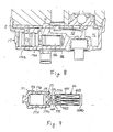
- the operation of bellows 452 is disposed on the space in which the pressure of crank chamber 32 is introduced, and pressure of suction chamber is applied to one end portion of bellow 452.
- the bellow may be disposed on the space in which the pressure of suction chamber 341 is introduced, and the pressure in the crank chamber 32 is applied to one end portion of bellows 452, as shown in Figure 8.
- the construction of the control mechanism utilized in this embodiment is the same as that o control mechanism 17 which is explained with reference to Figure 2.
- control mechanism 17 is provided with an electro magnetic actuator 46, the construction of which is clearly explained with reference to Figure 5. Therefore, the angle of inclination of wobble plate 40 is varied in accordance with operation of control mechanism 17, as previously explained.
- the compressor is operated at high capacity.
- Vacuum actuator 50 will be replaced for electromagnetic actuator 46 of the first embodiment.
- Vacuum actuator 50 includes a casing 502 which is divided into an air chamber 502a and a negative pressure chamber 502b with a diaphragm 501, and a tubular extension 503 which is connected with casing 502.
- An operating pin 504 is reciprocably disposed within the tubular extension 503 and fixed on diaphragm 501.
- Tubular extension 503 is provided with a stopper portion 505 for limiting the axial moving range of operating pin 504 at the inner end portion thereof.
- Coil spring 506 is disposed between stopper portion 505 and diaphragm 501 for supporting diaphragm 501 at the stationary position.
- O-rings 507 and packing 508 are disposed on the outer surface of the operating pin 504 for sealing between pin 504 and tubular extension 503.
- a screw 503a is formed on the outer surface of tubular extension 503 in order to fix vacuum actuator 50 within cylinder head 34 and a nut 51.
- control valve mechanism 45 can control opening and closing of aperture 451b.
- actuator 46 depends upon the temperature of the compartment of the automobile. If the temperature of the compartment is exceeding a predetermined temperature of which situation is indicated that the high refrigerant capacity is required, the electromagnetic coil 463 of actuator 46 is energized. Therefore, the compressor is operated under maximum capacity, even if the suction pressure is below the predetermined level. On the other hand, if the temperature of the compartment is below the predetermined temperature of which situation is indicated that very small refrigerant capacity is sufficient to compensate the change of temperature, the electromagnetic coil 463 is not energized.
Landscapes
- Engineering & Computer Science (AREA)
- Mechanical Engineering (AREA)
- General Engineering & Computer Science (AREA)
- Compressors, Vaccum Pumps And Other Relevant Systems (AREA)
- Compressor (AREA)
Applications Claiming Priority (2)
| Application Number | Priority Date | Filing Date | Title |
|---|---|---|---|
| JP61169897A JPS6329067A (ja) | 1986-07-21 | 1986-07-21 | 連続容量可変型揺動式圧縮機 |
| JP169897/86 | 1986-07-21 |
Publications (2)
| Publication Number | Publication Date |
|---|---|
| EP0256334A1 true EP0256334A1 (de) | 1988-02-24 |
| EP0256334B1 EP0256334B1 (de) | 1989-11-08 |
Family
ID=15894990
Family Applications (1)
| Application Number | Title | Priority Date | Filing Date |
|---|---|---|---|
| EP87110523A Expired EP0256334B1 (de) | 1986-07-21 | 1987-07-21 | Schiefscheibenverdichter mit Vorrichtung zur Hubveränderung |
Country Status (6)
| Country | Link |
|---|---|
| US (1) | US4780059A (de) |
| EP (1) | EP0256334B1 (de) |
| JP (1) | JPS6329067A (de) |
| KR (1) | KR960000089B1 (de) |
| AU (1) | AU603367B2 (de) |
| DE (1) | DE3760973D1 (de) |
Cited By (6)
| Publication number | Priority date | Publication date | Assignee | Title |
|---|---|---|---|---|
| EP0366348A1 (de) * | 1988-10-24 | 1990-05-02 | Sanden Corporation | Schrägscheibenverdichter mit einem Mechanismus zur Veränderung der Verdrängung |
| US5094589A (en) * | 1990-03-20 | 1992-03-10 | Sanden Corporation | Slant plate type compressor with variable displacement mechanism |
| US5145325A (en) * | 1989-06-28 | 1992-09-08 | Sanden Corporation | Slant plate type compressor with variable displacement mechanism |
| EP0947696A1 (de) * | 1998-04-03 | 1999-10-06 | Sanden Corporation | Taumelscheibenkompressor mit leichter und rascher Anpassung des Kurbelgehäusedrucks |
| FR2794187A1 (fr) * | 1999-03-26 | 2000-12-01 | Sanden Corp | Valve de controle de deplacement et compresseur a deplacement variable utilisant une telle valve |
| EP1024285A3 (de) * | 1999-01-29 | 2001-02-07 | Kabushiki Kaisha Toyoda Jidoshokki Seisakusho | Regelventil für einen Kompressor mit veränderlicher Verdrängung |
Families Citing this family (37)
| Publication number | Priority date | Publication date | Assignee | Title |
|---|---|---|---|---|
| JPS6375371A (ja) * | 1986-09-16 | 1988-04-05 | Sanden Corp | 容量可変圧縮機 |
| US4875834A (en) * | 1987-02-19 | 1989-10-24 | Sanden Corporation | Wobble plate type compressor with variable displacement mechanism |
| JPS63205469A (ja) * | 1987-02-20 | 1988-08-24 | Sanden Corp | 容量可変型斜板式圧縮機 |
| JPS63149319U (de) * | 1987-03-24 | 1988-09-30 | ||
| JPS63289286A (ja) * | 1987-05-20 | 1988-11-25 | Matsushita Electric Ind Co Ltd | 能力制御コンプレッサ |
| US5027612A (en) * | 1987-09-22 | 1991-07-02 | Sanden Corporation | Refrigerating system having a compressor with an internally and externally controlled variable displacement mechanism |
| US5189886A (en) * | 1987-09-22 | 1993-03-02 | Sanden Corporation | Refrigerating system having a compressor with an internally and externally controlled variable displacement mechanism |
| JPS6480776A (en) * | 1987-09-22 | 1989-03-27 | Sanden Corp | Volume-variable compressor |
| US5168716A (en) * | 1987-09-22 | 1992-12-08 | Sanden Corporation | Refrigeration system having a compressor with an internally and externally controlled variable displacement mechanism |
| JPH01177466A (ja) * | 1987-12-28 | 1989-07-13 | Diesel Kiki Co Ltd | 可変容量型揺動板式圧縮機の圧力制御弁 |
| JPH01182580A (ja) * | 1988-01-13 | 1989-07-20 | Sanden Corp | 容量可変型揺動式圧縮機 |
| JPH0447431Y2 (de) * | 1988-04-23 | 1992-11-09 | ||
| JP2600317B2 (ja) * | 1988-08-11 | 1997-04-16 | 株式会社豊田自動織機製作所 | 可変容量圧縮機 |
| JPH02274612A (ja) * | 1989-04-17 | 1990-11-08 | Sanden Corp | 自動車用空調装置の制御装置 |
| JP2567947B2 (ja) * | 1989-06-16 | 1996-12-25 | 株式会社豊田自動織機製作所 | 可変容量圧縮機 |
| JPH0343685A (ja) * | 1989-07-05 | 1991-02-25 | Sanden Corp | 容量可変型揺動式圧縮機 |
| JP2945748B2 (ja) * | 1990-11-16 | 1999-09-06 | サンデン株式会社 | 容量可変型揺動式圧縮機 |
| US5177973A (en) * | 1991-03-19 | 1993-01-12 | Ranco Incorporated Of Delaware | Refrigeration system subcooling flow control valve |
| US5156017A (en) * | 1991-03-19 | 1992-10-20 | Ranco Incorporated Of Delaware | Refrigeration system subcooling flow control valve |
| JP3088536B2 (ja) * | 1991-12-26 | 2000-09-18 | サンデン株式会社 | 可変容量型揺動式圧縮機 |
| JP3178631B2 (ja) * | 1993-01-11 | 2001-06-25 | 株式会社豊田自動織機製作所 | 可変容量型圧縮機用制御弁 |
| US5540203A (en) * | 1994-10-05 | 1996-07-30 | Ford Motor Company | Integrated hydraulic system for automotive vehicle |
| JPH1182300A (ja) * | 1997-09-05 | 1999-03-26 | Sanden Corp | 可変容量圧縮機 |
| JPH1193832A (ja) * | 1997-09-25 | 1999-04-06 | Sanden Corp | 可変容量圧縮機 |
| US6138468A (en) * | 1998-02-06 | 2000-10-31 | Kabushiki Kaisha Toyoda Jidoshokki Seisakusho | Method and apparatus for controlling variable displacement compressor |
| JP4051134B2 (ja) | 1998-06-12 | 2008-02-20 | サンデン株式会社 | 可変容量圧縮機の容量制御弁機構 |
| JP2000009034A (ja) * | 1998-06-25 | 2000-01-11 | Toyota Autom Loom Works Ltd | 空調システム |
| JP4111593B2 (ja) | 1998-07-07 | 2008-07-02 | サンデン株式会社 | 可変容量圧縮機の容量制御弁機構 |
| JP4181274B2 (ja) | 1998-08-24 | 2008-11-12 | サンデン株式会社 | 圧縮機 |
| JP2000111177A (ja) * | 1998-10-05 | 2000-04-18 | Toyota Autom Loom Works Ltd | 空調装置 |
| JP4118414B2 (ja) | 1998-10-29 | 2008-07-16 | サンデン株式会社 | 可変容量圧縮機の容量制御弁の制御回路 |
| EP1026397A3 (de) * | 1999-02-01 | 2001-02-07 | Kabushiki Kaisha Toyoda Jidoshokki Seisakusho | Regelventil für einen Kompressor mit veränderlicher Verdrängung |
| USD467871S1 (en) | 2000-06-07 | 2002-12-31 | Sanden Corporation | Electrical connector housing for an electromagnetic control valve |
| JP4926343B2 (ja) | 2001-08-08 | 2012-05-09 | サンデン株式会社 | 圧縮機の容量制御装置 |
| KR100858604B1 (ko) * | 2001-11-30 | 2008-09-17 | 가부시기가이샤 후지고오키 | 가변용량형 압축기용 제어밸브 |
| JP4162419B2 (ja) * | 2002-04-09 | 2008-10-08 | サンデン株式会社 | 可変容量圧縮機 |
| JP4118587B2 (ja) | 2002-04-09 | 2008-07-16 | サンデン株式会社 | 可変容量圧縮機 |
Citations (2)
| Publication number | Priority date | Publication date | Assignee | Title |
|---|---|---|---|---|
| DE3545581A1 (de) * | 1984-12-28 | 1986-07-10 | Kabushiki Kaisha Toyoda Jidoshokki Seisakusho, Kariya, Aichi | Taumelscheibenkompressor mit variablem hub |
| US4606705A (en) * | 1985-08-02 | 1986-08-19 | General Motors Corporation | Variable displacement compressor control valve arrangement |
Family Cites Families (22)
| Publication number | Priority date | Publication date | Assignee | Title |
|---|---|---|---|---|
| US27844A (en) * | 1860-04-10 | Bed-cord tightener | ||
| US862867A (en) * | 1906-03-28 | 1907-08-06 | Lewis Watson Eggleston | Pneumatic pumping apparatus. |
| US2530507A (en) * | 1945-10-25 | 1950-11-21 | John F Campbell | Fuel injection apparatus and control |
| US2573863A (en) * | 1948-05-19 | 1951-11-06 | Alva E Mitchell | Compressor |
| US2964234A (en) * | 1954-05-13 | 1960-12-13 | Houdaille Industries Inc | Constant clearance volume compressor |
| USRE27844E (en) | 1972-09-18 | 1973-12-18 | Compressor unit with self-contained drive means | |
| US3861829A (en) * | 1973-04-04 | 1975-01-21 | Borg Warner | Variable capacity wobble plate compressor |
| JPS51181A (ja) * | 1974-06-18 | 1976-01-05 | Matsushita Electric Works Ltd | Shomeikigu |
| US4073603A (en) * | 1976-02-06 | 1978-02-14 | Borg-Warner Corporation | Variable displacement compressor |
| US4037993A (en) * | 1976-04-23 | 1977-07-26 | Borg-Warner Corporation | Control system for variable displacement compressor |
| US4145163A (en) * | 1977-09-12 | 1979-03-20 | Borg-Warner Corporation | Variable capacity wobble plate compressor |
| US4174191A (en) * | 1978-01-18 | 1979-11-13 | Borg-Warner Corporation | Variable capacity compressor |
| JPS55380A (en) * | 1979-05-15 | 1980-01-05 | Dai Ichi Seiyaku Co Ltd | Preparation of dibenzoxepin derivative |
| US4433596A (en) * | 1980-03-11 | 1984-02-28 | Joseph Scalzo | Wabbler plate engine mechanisms |
| US4425837A (en) * | 1981-09-28 | 1984-01-17 | General Motors Corporation | Variable displacement axial piston machine |
| US4428718A (en) * | 1982-02-25 | 1984-01-31 | General Motors Corporation | Variable displacement compressor control valve arrangement |
| US4475871A (en) * | 1982-08-02 | 1984-10-09 | Borg-Warner Corporation | Variable displacement compressor |
| US4526516A (en) * | 1983-02-17 | 1985-07-02 | Diesel Kiki Co., Ltd. | Variable capacity wobble plate compressor capable of controlling angularity of wobble plate with high responsiveness |
| US4492527A (en) * | 1983-02-17 | 1985-01-08 | Diesel Kiki Co., Ltd. (Japanese Corp.) | Wobble plate piston pump |
| JPS60162087A (ja) * | 1984-02-02 | 1985-08-23 | Sanden Corp | 容量制御型コンプレツサ装置 |
| US4688997A (en) * | 1985-03-20 | 1987-08-25 | Kabushiki Kaisha Toyoda Jidoshokki Seisakusho | Variable displacement compressor with variable angle wobble plate and wobble angle control unit |
| JPS62674A (ja) * | 1985-06-27 | 1987-01-06 | Toyoda Autom Loom Works Ltd | 角度可変揺動斜板型可変容量圧縮機の容量制御装置 |
-
1986
- 1986-07-21 JP JP61169897A patent/JPS6329067A/ja active Pending
-
1987
- 1987-07-20 AU AU75913/87A patent/AU603367B2/en not_active Ceased
- 1987-07-21 US US07/075,968 patent/US4780059A/en not_active Expired - Lifetime
- 1987-07-21 EP EP87110523A patent/EP0256334B1/de not_active Expired
- 1987-07-21 KR KR1019870007881A patent/KR960000089B1/ko not_active Expired - Fee Related
- 1987-07-21 DE DE8787110523T patent/DE3760973D1/de not_active Expired
Patent Citations (2)
| Publication number | Priority date | Publication date | Assignee | Title |
|---|---|---|---|---|
| DE3545581A1 (de) * | 1984-12-28 | 1986-07-10 | Kabushiki Kaisha Toyoda Jidoshokki Seisakusho, Kariya, Aichi | Taumelscheibenkompressor mit variablem hub |
| US4606705A (en) * | 1985-08-02 | 1986-08-19 | General Motors Corporation | Variable displacement compressor control valve arrangement |
Cited By (7)
| Publication number | Priority date | Publication date | Assignee | Title |
|---|---|---|---|---|
| EP0366348A1 (de) * | 1988-10-24 | 1990-05-02 | Sanden Corporation | Schrägscheibenverdichter mit einem Mechanismus zur Veränderung der Verdrängung |
| US5145325A (en) * | 1989-06-28 | 1992-09-08 | Sanden Corporation | Slant plate type compressor with variable displacement mechanism |
| US5094589A (en) * | 1990-03-20 | 1992-03-10 | Sanden Corporation | Slant plate type compressor with variable displacement mechanism |
| EP0947696A1 (de) * | 1998-04-03 | 1999-10-06 | Sanden Corporation | Taumelscheibenkompressor mit leichter und rascher Anpassung des Kurbelgehäusedrucks |
| EP1024285A3 (de) * | 1999-01-29 | 2001-02-07 | Kabushiki Kaisha Toyoda Jidoshokki Seisakusho | Regelventil für einen Kompressor mit veränderlicher Verdrängung |
| US6257836B1 (en) | 1999-01-29 | 2001-07-10 | Kabushiki Kaisha Toyoda Jidoshokki Seisakusho | Displacement control valve for variable displacement compressor |
| FR2794187A1 (fr) * | 1999-03-26 | 2000-12-01 | Sanden Corp | Valve de controle de deplacement et compresseur a deplacement variable utilisant une telle valve |
Also Published As
| Publication number | Publication date |
|---|---|
| AU603367B2 (en) | 1990-11-15 |
| AU7591387A (en) | 1988-01-28 |
| EP0256334B1 (de) | 1989-11-08 |
| KR880001920A (ko) | 1988-04-28 |
| KR960000089B1 (ko) | 1996-01-03 |
| DE3760973D1 (en) | 1989-12-14 |
| JPS6329067A (ja) | 1988-02-06 |
| US4780059A (en) | 1988-10-25 |
Similar Documents
| Publication | Publication Date | Title |
|---|---|---|
| EP0256334A1 (de) | Schiefscheibenverdichter mit Vorrichtung zur Hubveränderung | |
| KR950010405B1 (ko) | 용량 가변 기구를 구비한 요동판식 압축기 | |
| EP0297514B1 (de) | Kältemittelkreislauf mit Durchgangsregelungsmechanismus | |
| US4936752A (en) | Slant plate type compressor with variable displacement mechanism | |
| CA1235402A (en) | Refrigerant compressor with a capacity adjusting mechanism | |
| US6010312A (en) | Control valve unit with independently operable valve mechanisms for variable displacement compressor | |
| US5890876A (en) | Control valve in variable displacement compressor | |
| US5964578A (en) | Control valve in variable displacement compressor | |
| US4632640A (en) | Wobble plate type compressor with a capacity adjusting mechanism | |
| US6257836B1 (en) | Displacement control valve for variable displacement compressor | |
| US5165863A (en) | Slant plate type compressor with variable capacity control mechanism | |
| US5094589A (en) | Slant plate type compressor with variable displacement mechanism | |
| US4960366A (en) | Slant plate type compressor with variable displacement mechanism | |
| EP0945617B1 (de) | Kontrollventil zur Kapazitätseinstellung eines Verstellkompressors | |
| EP0405878B1 (de) | Schiefscheibenverdichter mit einer Vorrichtung zur Hubveränderung | |
| KR970001753B1 (ko) | 가변 용량 기구를 구비한 요동판형 압축기 | |
| JP3150728B2 (ja) | 斜板式コンプレッサー | |
| EP0845593B1 (de) | Verdrängungsvariabler Taumelscheibenkompressor mit Steuerungsmechanismus | |
| EP0519598A1 (de) | Schiefscheibenverdichter mit Vorrichtung zur Hubveränderung | |
| JPH1182296A (ja) | 可変容量圧縮機 | |
| JPH10141223A (ja) | 可変容量圧縮機 | |
| US7210911B2 (en) | Controller for variable displacement compressor and control method for the same | |
| EP0900936A2 (de) | Kompressor mit einstellbarer Fördermenge, bei dem das Eindringen von flüssigem Kältemittel in die Kurbelkammer verhindert wird | |
| US6321545B1 (en) | Control apparatus for variable displacement type compressor | |
| US5255569A (en) | Slant plate type compressor with variable displacement mechanism |
Legal Events
| Date | Code | Title | Description |
|---|---|---|---|
| PUAI | Public reference made under article 153(3) epc to a published international application that has entered the european phase |
Free format text: ORIGINAL CODE: 0009012 |
|
| AK | Designated contracting states |
Kind code of ref document: A1 Designated state(s): DE FR GB IT SE |
|
| 17P | Request for examination filed |
Effective date: 19880425 |
|
| 17Q | First examination report despatched |
Effective date: 19880812 |
|
| ITF | It: translation for a ep patent filed | ||
| GRAA | (expected) grant |
Free format text: ORIGINAL CODE: 0009210 |
|
| AK | Designated contracting states |
Kind code of ref document: B1 Designated state(s): DE FR GB IT SE |
|
| REF | Corresponds to: |
Ref document number: 3760973 Country of ref document: DE Date of ref document: 19891214 |
|
| ET | Fr: translation filed | ||
| PLBE | No opposition filed within time limit |
Free format text: ORIGINAL CODE: 0009261 |
|
| STAA | Information on the status of an ep patent application or granted ep patent |
Free format text: STATUS: NO OPPOSITION FILED WITHIN TIME LIMIT |
|
| 26N | No opposition filed | ||
| ITTA | It: last paid annual fee | ||
| EAL | Se: european patent in force in sweden |
Ref document number: 87110523.5 |
|
| PGFP | Annual fee paid to national office [announced via postgrant information from national office to epo] |
Ref country code: GB Payment date: 19950710 Year of fee payment: 9 |
|
| PGFP | Annual fee paid to national office [announced via postgrant information from national office to epo] |
Ref country code: FR Payment date: 19950711 Year of fee payment: 9 |
|
| PGFP | Annual fee paid to national office [announced via postgrant information from national office to epo] |
Ref country code: SE Payment date: 19950717 Year of fee payment: 9 |
|
| PGFP | Annual fee paid to national office [announced via postgrant information from national office to epo] |
Ref country code: DE Payment date: 19950725 Year of fee payment: 9 |
|
| PG25 | Lapsed in a contracting state [announced via postgrant information from national office to epo] |
Ref country code: GB Effective date: 19960721 |
|
| PG25 | Lapsed in a contracting state [announced via postgrant information from national office to epo] |
Ref country code: SE Effective date: 19960722 |
|
| GBPC | Gb: european patent ceased through non-payment of renewal fee |
Effective date: 19960721 |
|
| PG25 | Lapsed in a contracting state [announced via postgrant information from national office to epo] |
Ref country code: FR Effective date: 19970328 |
|
| PG25 | Lapsed in a contracting state [announced via postgrant information from national office to epo] |
Ref country code: DE Effective date: 19970402 |
|
| EUG | Se: european patent has lapsed |
Ref document number: 87110523.5 |
|
| REG | Reference to a national code |
Ref country code: FR Ref legal event code: ST |
|
| PG25 | Lapsed in a contracting state [announced via postgrant information from national office to epo] |
Ref country code: IT Free format text: LAPSE BECAUSE OF NON-PAYMENT OF DUE FEES;WARNING: LAPSES OF ITALIAN PATENTS WITH EFFECTIVE DATE BEFORE 2007 MAY HAVE OCCURRED AT ANY TIME BEFORE 2007. THE CORRECT EFFECTIVE DATE MAY BE DIFFERENT FROM THE ONE RECORDED. Effective date: 20050721 |