EP0256510B1 - Halter für optische Faser - Google Patents
Halter für optische Faser Download PDFInfo
- Publication number
- EP0256510B1 EP0256510B1 EP87111687A EP87111687A EP0256510B1 EP 0256510 B1 EP0256510 B1 EP 0256510B1 EP 87111687 A EP87111687 A EP 87111687A EP 87111687 A EP87111687 A EP 87111687A EP 0256510 B1 EP0256510 B1 EP 0256510B1
- Authority
- EP
- European Patent Office
- Prior art keywords
- optical fiber
- rollers
- holding
- bodies
- supporting member
- Prior art date
- Legal status (The legal status is an assumption and is not a legal conclusion. Google has not performed a legal analysis and makes no representation as to the accuracy of the status listed.)
- Expired - Lifetime
Links
- 239000013307 optical fiber Substances 0.000 title claims description 87
- 239000000758 substrate Substances 0.000 description 6
- 239000000835 fiber Substances 0.000 description 4
- 230000005484 gravity Effects 0.000 description 3
- 238000005452 bending Methods 0.000 description 2
- 230000006835 compression Effects 0.000 description 2
- 238000007906 compression Methods 0.000 description 2
- 238000000034 method Methods 0.000 description 2
- 239000000428 dust Substances 0.000 description 1
- 230000004927 fusion Effects 0.000 description 1
- 230000002265 prevention Effects 0.000 description 1
- 238000007788 roughening Methods 0.000 description 1
Images
Classifications
-
- G—PHYSICS
- G02—OPTICS
- G02B—OPTICAL ELEMENTS, SYSTEMS OR APPARATUS
- G02B6/00—Light guides; Structural details of arrangements comprising light guides and other optical elements, e.g. couplings
- G02B6/24—Coupling light guides
- G02B6/255—Splicing of light guides, e.g. by fusion or bonding
- G02B6/2555—Alignment or adjustment devices for aligning prior to splicing
-
- G—PHYSICS
- G02—OPTICS
- G02B—OPTICAL ELEMENTS, SYSTEMS OR APPARATUS
- G02B6/00—Light guides; Structural details of arrangements comprising light guides and other optical elements, e.g. couplings
- G02B6/24—Coupling light guides
- G02B6/36—Mechanical coupling means
- G02B6/3616—Holders, macro size fixtures for mechanically holding or positioning fibres, e.g. on an optical bench
-
- G—PHYSICS
- G02—OPTICS
- G02B—OPTICAL ELEMENTS, SYSTEMS OR APPARATUS
- G02B6/00—Light guides; Structural details of arrangements comprising light guides and other optical elements, e.g. couplings
- G02B6/24—Coupling light guides
- G02B6/36—Mechanical coupling means
- G02B6/3628—Mechanical coupling means for mounting fibres to supporting carriers
- G02B6/3648—Supporting carriers of a microbench type, i.e. with micromachined additional mechanical structures
- G02B6/3652—Supporting carriers of a microbench type, i.e. with micromachined additional mechanical structures the additional structures being prepositioning mounting areas, allowing only movement in one dimension, e.g. grooves, trenches or vias in the microbench surface, i.e. self aligning supporting carriers
Definitions
- This invention relates to an optical fiber holder and, more particularly, a holder for holding an optical fiber whilst allowing it to be moved along its longitudinal direction.
- V-shaped groove splicing As an optical fiber splicing process, V-shaped groove splicing has been known in which two lengths of optical fibers are connected in series by positioning optical fibers in a V-shaped groove of a substrate to butt them at their ends and then bond them by fusion. In such a process, the prevention of an excess stress acting on the optical fibers to be spliced is a serious problem. Since the optical fibers are easily damaged by an excess tensile force, bending or torsion, it is necessary to introduce the optical fibers into the groove of the substrate so that they have a curvature as large as possible.
- optical fiber holders which are arranged on opposite sides of the substrate to hold each optical fiber at the most bent portion of the optical fiber to be spliced so that each optical fiber is movable in the axial direction.
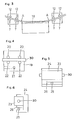
- One of the known optical fiber holders comprises, as shown in Figs. 4, plural pairs of fixed pins 20 and movable pins 22 so arranged that they are facing each other in parallel, said movable pins 22 being fixed to a movable plate 19 forced upwardly by a spring 21.
- an optical fiber 30 to be spliced is put between the fixed pins 20 and movable pins 22 to hold it by the frictional force between the optical fiber 30 and pins 20, 22.
- Another optical fiber holder comprises, as shown in Figs. 5 and 6, a holding guide 23 put between a main body 24 and a push plate 26 forced upwardly by a spring 25.
- an optical fiber 30 is inserted into the guide member 23 held between the main body 24 and push plate 26 by the frictional force between them. If the holder is used under inclined conditions, the guide member 23 receives a force causing its sliding movement under the influence of gravity. For this reason, the axial force varies with the inclination angle of the holder, thus making it difficult to hold the optical fibers under the predetermined constant holding force so that they are movable in the axial direction.
- GB-A-2 135 474 discloses an optical fiber chuck for use in an optical fiber splicer as an optical fiber holder which comprises a lower holding body intended to rest horizontally.
- Said optical fiber holder also includes an upper holding body, which is pivotably mounted on the lower body about a horizontal axis.
- the optical fiber holder also comprises one upper roller and one lower roller respectively mounted on of the holding bodies.
- the upper and lower rollers face each other, so as to firmly hold the optical fiber interposed therebetween and allows the optical fiber to be moved along its longitudinal direction.
- the upper roller presses the optical fiber against the lower roller.
- a V-shaped insert engages the optical fiber positioned in the V-groove of the lower body in order to hold the optical fiber.
- Said prior art optical fiber holder is disadvantageous in that it is impossible with this holder to hold the optical fiber under a constant holding force.
- an object of the present invention to provide an optical fiber holder used for connecting in series two lengths of optical fiber, which makes it possible to hold the optical fiber under a constant holding force, so that the optical fiber is free to move in its longitudinal direction without receiving any excess stress.
- this object is solved by: a lower holding body intended to rest horizontally, and an upper holding body pivotably mounted on the lower body about a horizontal axis so as to be movable between an upper position for which the bodies are spaced apart from each other and the optical fibre is free to move laterally and a substantially horizontal lower position for which the bodies are close together and the optical fiber is firmly held laterally; at least one supporting member slidably mounted on one of the holding bodies; and at least one pair of upper rollers and one pair of lower rollers facing each other when the bodies are in their close position, one of said pairs of upper or lower rollers being rotatably mounted on the slidable supporting member so that the line passing through the axes of the rollers of said one pair is inclined with respect to the horizontal in the close position of the holding bodies, and the other of said pairs being mounted on the other holding body which does not support said slidable supporting member so that the line passing through the axes of the rollers of said other pair is substantially parallel to the line passing through the axes
- the rollers are provided with a frictional layer, i.e., an outer layer having a high frictional resistance to prevent slip between the rollers and optical fiber.
- a frictional layer makes it possible to rotate the rollers in response to the forces applied in the axial direction of the optical fiber.
- two optical fiber holders are arranged on opposite sides of a V-grooved substrate and two lengths of optical fibers to be spliced are put between pairs of upper and lower rollers of the respective holders so that the ends of the fibers face downwardly.
- a force is applied to the optical fiber in the axial directions of the respective optical fibers, so that the rollers rotate in response to the axial movement of the optical fiber.
- a downward force is applied to the optical fiber under the influence of gravity, so that the end of each fiber is forced to the bottom of the V-shaped groove, thus making it possible to prevent it from floating in the air.
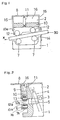
- an optical fiber holder embodying the present invention which comprises a lower fixed holding body 1 and an upper movable holding body 2 pivotally mounted on the fixed holding body 1 by a shaft 3.
- the upper holding body 1 is pulled toward the fixed holding body 2 by a tension spring 4 which is hooked at its opposite ends to the holding bodies 1 and 2.
- the fixed holding body 1 is provided at its upper part with a stopper 5 to prevent excessive movement of the movable holding body 2.
- the movable holding body 2 is provided at its top with a horizontal plate 8 extending forwardly, and at its opposite sides with side plates 15 to form a housing 16 for a supporting member 10 in cooperation with a front plate 9 extending downwardly from the top plate 8.
- the supporting member 10 is slidably mounted in the housing 16 and forced downwardly by a compression spring 11 which is arranged between the top plate 8 and supporting member 10 so that the upper rollers 12 come close to the lower fixed rollers 7.
- the supporting member 10 has a pair of flanges 10a extending downwardly from its front and rear parts.
- the optical fiber holder is provided with plural pairs of lower rollers 7 and upper rollers 12.
- the lower rollers 7 are rotatably mounted on the front part of the fixed holding body 1 by roller shafts 6 so that the roller 7 on the side of the guide plate 14 (in Fig. 1, right roller 7) is positioned at a level higher than the other so that they are arranged on a line passing through the axes of the rollers, which is inclined with respect to the horizontal line.
- the upper rollers 12 are rotatably mounted on the supporting member 10 by roller shafts 13 so that the upper and lower rollers 12 and 7 are put in pairs, face to face.
- the rollers 7 and 12 are respectively composed of a cylindrical body 12a, and a rubber layer 12b integrally formed thereon to form a layer having a high frictional resistance. Such a frictional layer may be formed by roughening the surface of the rollers.
- the upper or lower rollers may be fixed rollers or fixed guiding members, provided that the others are rotatable rollers.
- the fixed holding body 1 is provided at its one side with a guide member 14 through which an optical fiber 30 is introduced between the upper and lower rollers 12 and 7.
- the thus constructed optical fiber holder is operated in the following manner; Firstly, the upper holding body 2 is pivoted upwardly by lifting the front part of the top plate 8 to increase the distance between the lower and upper rollers 7, 12 and, after inserting an optical fiber 30 between the rollers through the guide plate 14, the upper holding body 2 is returned to the horizontal position to put the optical fiber 30 between the upper and lower rollers 7, 12.
- the upper rollers 12 are forced toward the lower rollers 7 by the spring 11, so that the optical fiber 30 is held by the frictional force between the contacting surfaces of the optical fiber 30 and rollers 7, 12.
- the force of spring is so determined that the holding forces acting on the optical fiber 30 is sufficiently greater than the sliding frictional force between the optical fiber 30 and rollers 7, 12.
- the rollers 7, 12 rotate clockwise or counterclockwise to move the optical fiber 30 in its axial direction.
- the optical fiber 30 does not slide on the rollers 7, 12, but is moved by the rotational motion of the rollers, so that the optical fiber 30 is pulled in the axial direction smoothly.
- the optical fiber Since the optical fiber is diagonally held by the holder so that its end faces downwardly, a downward force is applied to the optical fiber under the influence or gravity, thus making it possible to prevent the end of each fiber from floating in the air, which in turn makes it possible to align the optical fibers in the V-shaped groove of the substrate.
- the supporting member 10 is slidably mounted on the upper holding body 2, but it may be slidably mounted on the lower holding body 1. Also, it is possible to slidably mount supporting members on both of the upper and lower holding bodies respectively.
Landscapes
- Physics & Mathematics (AREA)
- General Physics & Mathematics (AREA)
- Optics & Photonics (AREA)
- Engineering & Computer Science (AREA)
- Plasma & Fusion (AREA)
- Mechanical Coupling Of Light Guides (AREA)
Claims (2)
- Lichtleitfaserhalter zur Halterung einer Lichtleitfaser (30) bei gleichzeitig zugelassener Beweglichkeit entlang ihrer Längsrichtung, wobei der Halter aufweist:- einen unteren Haltekörper (1), der waagrecht aufsitzen soll, und einen oberen Haltekörper (2), der schwenkbar am unteren Körper (1) um eine waagrechte Achse (3) gelagert ist, so daß er zwischen einer oberen Stellung, in der die Körper (1, 2) relativ zueinander auf Abstand stehen und die Lichtleitfaser (30) sich frei zur Seite hin bewegen kann, und einer im wesentlichen waagrechten unteren Stellung beweglich ist, in der die Körper eng einander gegenüberstehen und die Lichtleitfaser (30) zur Seite hin festgehalten wird;- mindestens ein Tragelement (10), das gleitend an einem der Haltekörper gelagert ist; und- mindestens ein Paar oberer Rollen (12) und ein Paar unterer Rollen (7), die einander zugekehrt sind, wenn die Körper ihre geschlossene Position einnehmen, wobei eines der Paare der oberen oder unteren Rollen (12, 7) drehbar auf dem verschiebbaren Tragelement (10) befestigt ist, so daß die in der geschlossenen Position der Haltekörper verlaufende Linie durch die Achsen der Rollen (12; 7) des genannten einen Paares relativ zur Waagrechten geneigt ist, während das andere der Paare auf dem anderen Haltekörper befestigt ist, der kein verschiebbares Tragelement trägt, so daß die in der geschlossenen Position der Körper durch die Achsen der Rollen des anderen Paares verlaufende Linie im wesentlichen parallel zu der durch die Achsen der Rollen des einen Paares verlaufenden Linie liegt, wobei das Tragelement so montiert ist, daß es in der geschlossenen Position der Körper durch ein Federelement (11) gleitend in Richtung des anderen Körpers, der kein Halteelement trägt, gedrückt wird, so daß die darauf befestigten Rollen dicht an die gegenüberliegenden Rollen herankommen, wodurch die zwischen ihnen eingefügte Lichtleitfaser festgehalten wird, sich aber gleichzeitig in Längsrichtung bewegen kann.
- Lichtleitfaserhalter nach Anspruch 1, bei dem die Rollen (12, 7) mit einer äußeren Schicht versehen sind, die einen hohen Reibungswiderstand besitzt, um ein Schlüpfen zwischen den Rollen (12, 7) und der Lichtleitfaser (30) zu verhindern.
Applications Claiming Priority (2)
| Application Number | Priority Date | Filing Date | Title |
|---|---|---|---|
| JP190984/86 | 1986-08-12 | ||
| JP61190984A JPS6344605A (ja) | 1986-08-12 | 1986-08-12 | 光フアイバ把持具 |
Publications (3)
| Publication Number | Publication Date |
|---|---|
| EP0256510A2 EP0256510A2 (de) | 1988-02-24 |
| EP0256510A3 EP0256510A3 (en) | 1990-05-23 |
| EP0256510B1 true EP0256510B1 (de) | 1994-01-26 |
Family
ID=16266924
Family Applications (1)
| Application Number | Title | Priority Date | Filing Date |
|---|---|---|---|
| EP87111687A Expired - Lifetime EP0256510B1 (de) | 1986-08-12 | 1987-08-12 | Halter für optische Faser |
Country Status (4)
| Country | Link |
|---|---|
| US (1) | US4768855A (de) |
| EP (1) | EP0256510B1 (de) |
| JP (1) | JPS6344605A (de) |
| DE (1) | DE3788906T2 (de) |
Families Citing this family (19)
| Publication number | Priority date | Publication date | Assignee | Title |
|---|---|---|---|---|
| US4890896A (en) * | 1988-05-26 | 1990-01-02 | Minnesota Mining And Manufacturing Company | Connecting device for optical fibers |
| JP2670378B2 (ja) * | 1990-04-10 | 1997-10-29 | 古河電気工業株式会社 | 光ファイバの簡易突合せ装置 |
| GB2330424B (en) * | 1997-11-21 | 1999-09-08 | Bookham Technology Ltd | Apparatus for connecting an optical fibre to an optical device |
| DE102011101540B4 (de) * | 2011-05-14 | 2013-01-03 | Höfer Metall Technik GmbH & Co. KG | Verfahren zur Montage von Lichtleitern |
| EP3117250A4 (de) * | 2014-03-14 | 2017-10-04 | AFL Telecommunications LLC | Verfahren zur herstellung von fasern mit gebogener spitze |
| WO2021174117A1 (en) | 2020-02-28 | 2021-09-02 | Bard Access Systems, Inc. | Catheter with optic shape sensing capabilities |
| CN113325524B (zh) | 2020-02-28 | 2026-01-02 | 巴德阿克塞斯系统股份有限公司 | 光学连接系统及其方法 |
| CN113332561B (zh) | 2020-03-03 | 2026-04-14 | 巴德阿克塞斯系统股份有限公司 | 用于光学形状感测和电信号传导的系统和方法 |
| WO2021202589A1 (en) | 2020-03-30 | 2021-10-07 | Bard Access Systems, Inc. | Optical and electrical diagnostic systems and methods thereof |
| WO2022109045A1 (en) * | 2020-11-18 | 2022-05-27 | Bard Access Systems, Inc. | Optical-fiber stylet holders and methods thereof |
| EP4247247B1 (de) | 2020-11-24 | 2025-12-24 | Bard Access Systems, Inc. | Durch steuerbare faseroptische formmessung aktiviertes längliches medizinisches instrument |
| EP4320403A1 (de) | 2021-04-15 | 2024-02-14 | Bard Access Systems, Inc. | Erweitertes faseroptisches sensorsystem |
| EP4401659A1 (de) | 2021-09-16 | 2024-07-24 | Bard Access Systems, Inc. | Austauschbare faserverbindungsschnittstelle mit hohem paarungszyklus |
| US12318149B2 (en) | 2022-03-08 | 2025-06-03 | Bard Access Systems, Inc. | Medical shape sensing devices and systems |
| US12426956B2 (en) | 2022-03-16 | 2025-09-30 | Bard Access Systems, Inc. | Medical system and method for monitoring medical device insertion and illumination patterns |
| US12605116B2 (en) | 2022-04-11 | 2026-04-21 | Bard Access Systems, Inc. | Fiber optic medical systems and devices with electrical tip |
| US12685595B2 (en) | 2022-04-27 | 2026-07-21 | Bard Access Systems, Inc. | Conductor incorporated fiber enabled medical systems |
| US12575893B2 (en) | 2022-06-24 | 2026-03-17 | Bard Access Systems, Inc. | Shape sensing fiber optic tip protection systems and devices |
| US12564340B2 (en) | 2022-07-12 | 2026-03-03 | Bard Access Systems, Inc. | Eccentric single-core fiber-optic enabled medical device |
Family Cites Families (4)
| Publication number | Priority date | Publication date | Assignee | Title |
|---|---|---|---|---|
| FR2445972A1 (fr) * | 1979-01-03 | 1980-08-01 | Lyonnaise Transmiss Optiques | Dispositif de soudage de plusieurs fibres optiques bout a bout par nappes et procede de soudage a l'aide de ce dispositif |
| JPS5596912A (en) * | 1979-01-17 | 1980-07-23 | Nippon Telegr & Teleph Corp <Ntt> | Axial aligning method of optical fiber |
| JPS55130508A (en) * | 1979-03-30 | 1980-10-09 | Nippon Telegr & Teleph Corp <Ntt> | Connecting method of optical fiber |
| US4537466A (en) * | 1983-02-15 | 1985-08-27 | Raychem Corporation | Optical fiber chuck including a cover comprising an idler wheel and a V-shaped insert |
-
1986
- 1986-08-12 JP JP61190984A patent/JPS6344605A/ja active Pending
-
1987
- 1987-08-12 DE DE3788906T patent/DE3788906T2/de not_active Expired - Fee Related
- 1987-08-12 EP EP87111687A patent/EP0256510B1/de not_active Expired - Lifetime
- 1987-08-12 US US07/084,151 patent/US4768855A/en not_active Expired - Lifetime
Also Published As
| Publication number | Publication date |
|---|---|
| DE3788906D1 (de) | 1994-03-10 |
| EP0256510A3 (en) | 1990-05-23 |
| US4768855A (en) | 1988-09-06 |
| DE3788906T2 (de) | 1994-06-30 |
| JPS6344605A (ja) | 1988-02-25 |
| EP0256510A2 (de) | 1988-02-24 |
Similar Documents
| Publication | Publication Date | Title |
|---|---|---|
| US4768855A (en) | Optical fiber holder | |
| US8254739B2 (en) | Bladeless optical fiber cleaver and method | |
| US4017013A (en) | Multiple fiber end preparation | |
| US20140299645A1 (en) | Low cost, disposable optical fiber cleaver | |
| US4276113A (en) | Winged V-groove fiber optic clamp and splicer | |
| US20120141082A1 (en) | Bladeless optical fiber cleaver | |
| US7883275B2 (en) | Fiber guiding platform for mechanical splicer, optical connectors, fiber holder and methods | |
| US7001084B2 (en) | Fiber splice device | |
| JPH06317711A (ja) | 光ファイバ切断装置 | |
| CN1210596A (zh) | 用于使光纤配线架内的光纤接续器接通和断开的方法和系统 | |
| US4537466A (en) | Optical fiber chuck including a cover comprising an idler wheel and a V-shaped insert | |
| US7407333B2 (en) | Optical fiber fixing system, optical fiber butting system and optical fiber fusion-splicing system | |
| CN101099099B (zh) | 光纤夹持器 | |
| US5108021A (en) | Cleaving tool for optical fibers | |
| US4377323A (en) | Splicing device for producing a light waveguide connection | |
| US20220146760A1 (en) | Optical connector assembly | |
| JP4256766B2 (ja) | 光ファイバの切断方法及びファイバカッター | |
| US4377250A (en) | Method and a device for cutting a plurality of light waveguides united in a cable | |
| JPS6156483B2 (de) | ||
| US20050063645A1 (en) | Device for gripping optical fibers | |
| JPH04230823A (ja) | 光ファイバーの整列方法および装置 | |
| JP3288112B2 (ja) | 光ファイバのクランプ機構 | |
| EP0637763A1 (de) | Apparat zum schrägen Spalten optischer Fasern | |
| JP2896860B2 (ja) | 光多芯コネクタ | |
| US9358657B1 (en) | Recess forming tool for preparing fiber optic ferrule endfaces |
Legal Events
| Date | Code | Title | Description |
|---|---|---|---|
| PUAI | Public reference made under article 153(3) epc to a published international application that has entered the european phase |
Free format text: ORIGINAL CODE: 0009012 |
|
| AK | Designated contracting states |
Kind code of ref document: A2 Designated state(s): DE GB SE |
|
| PUAL | Search report despatched |
Free format text: ORIGINAL CODE: 0009013 |
|
| RHK1 | Main classification (correction) |
Ipc: G02B 6/36 |
|
| AK | Designated contracting states |
Kind code of ref document: A3 Designated state(s): DE GB SE |
|
| 17P | Request for examination filed |
Effective date: 19900717 |
|
| 17Q | First examination report despatched |
Effective date: 19920720 |
|
| GRAA | (expected) grant |
Free format text: ORIGINAL CODE: 0009210 |
|
| AK | Designated contracting states |
Kind code of ref document: B1 Designated state(s): DE GB SE |
|
| REF | Corresponds to: |
Ref document number: 3788906 Country of ref document: DE Date of ref document: 19940310 |
|
| PLBE | No opposition filed within time limit |
Free format text: ORIGINAL CODE: 0009261 |
|
| STAA | Information on the status of an ep patent application or granted ep patent |
Free format text: STATUS: NO OPPOSITION FILED WITHIN TIME LIMIT |
|
| 26N | No opposition filed | ||
| EAL | Se: european patent in force in sweden |
Ref document number: 87111687.7 |
|
| PGFP | Annual fee paid to national office [announced via postgrant information from national office to epo] |
Ref country code: DE Payment date: 19960816 Year of fee payment: 10 |
|
| REG | Reference to a national code |
Ref country code: GB Ref legal event code: 746 Effective date: 19970121 |
|
| PG25 | Lapsed in a contracting state [announced via postgrant information from national office to epo] |
Ref country code: DE Free format text: LAPSE BECAUSE OF NON-PAYMENT OF DUE FEES Effective date: 19980501 |
|
| REG | Reference to a national code |
Ref country code: GB Ref legal event code: IF02 |
|
| PGFP | Annual fee paid to national office [announced via postgrant information from national office to epo] |
Ref country code: SE Payment date: 20050804 Year of fee payment: 19 |
|
| PGFP | Annual fee paid to national office [announced via postgrant information from national office to epo] |
Ref country code: GB Payment date: 20050810 Year of fee payment: 19 |
|
| PG25 | Lapsed in a contracting state [announced via postgrant information from national office to epo] |
Ref country code: SE Free format text: LAPSE BECAUSE OF NON-PAYMENT OF DUE FEES Effective date: 20060813 |
|
| EUG | Se: european patent has lapsed | ||
| GBPC | Gb: european patent ceased through non-payment of renewal fee |
Effective date: 20060812 |
|
| PG25 | Lapsed in a contracting state [announced via postgrant information from national office to epo] |
Ref country code: GB Free format text: LAPSE BECAUSE OF NON-PAYMENT OF DUE FEES Effective date: 20060812 |