EP0256647A2 - Kohärente Mischung von optischen Signalen - Google Patents
Kohärente Mischung von optischen Signalen Download PDFInfo
- Publication number
- EP0256647A2 EP0256647A2 EP87305947A EP87305947A EP0256647A2 EP 0256647 A2 EP0256647 A2 EP 0256647A2 EP 87305947 A EP87305947 A EP 87305947A EP 87305947 A EP87305947 A EP 87305947A EP 0256647 A2 EP0256647 A2 EP 0256647A2
- Authority
- EP
- European Patent Office
- Prior art keywords
- optical
- phase
- detector
- mode
- modes
- Prior art date
- Legal status (The legal status is an assumption and is not a legal conclusion. Google has not performed a legal analysis and makes no representation as to the accuracy of the status listed.)
- Ceased
Links
- 230000003287 optical effect Effects 0.000 title claims abstract description 58
- 230000001427 coherent effect Effects 0.000 title description 11
- 238000009826 distribution Methods 0.000 claims abstract description 41
- 239000000835 fiber Substances 0.000 claims description 36
- 238000001514 detection method Methods 0.000 claims description 16
- 238000000034 method Methods 0.000 claims description 11
- 230000008878 coupling Effects 0.000 claims description 7
- 238000010168 coupling process Methods 0.000 claims description 7
- 238000005859 coupling reaction Methods 0.000 claims description 7
- 239000000203 mixture Substances 0.000 claims description 5
- 239000013307 optical fiber Substances 0.000 claims description 3
- 230000001902 propagating effect Effects 0.000 abstract description 5
- 230000000694 effects Effects 0.000 description 5
- 230000035559 beat frequency Effects 0.000 description 4
- 230000000295 complement effect Effects 0.000 description 4
- 238000005520 cutting process Methods 0.000 description 4
- 230000002452 interceptive effect Effects 0.000 description 4
- 239000006185 dispersion Substances 0.000 description 3
- 230000005484 gravity Effects 0.000 description 3
- 238000005253 cladding Methods 0.000 description 2
- 238000005516 engineering process Methods 0.000 description 2
- 230000003014 reinforcing effect Effects 0.000 description 2
- 230000005540 biological transmission Effects 0.000 description 1
- 238000010276 construction Methods 0.000 description 1
- 230000003111 delayed effect Effects 0.000 description 1
- 238000010586 diagram Methods 0.000 description 1
- 230000005684 electric field Effects 0.000 description 1
- 230000007717 exclusion Effects 0.000 description 1
- 230000000737 periodic effect Effects 0.000 description 1
- 230000002085 persistent effect Effects 0.000 description 1
- 238000003825 pressing Methods 0.000 description 1
- 230000035945 sensitivity Effects 0.000 description 1
- 238000000926 separation method Methods 0.000 description 1
Images


Classifications
-
- H—ELECTRICITY
- H04—ELECTRIC COMMUNICATION TECHNIQUE
- H04B—TRANSMISSION
- H04B10/00—Transmission systems employing electromagnetic waves other than radio-waves, e.g. infrared, visible or ultraviolet light, or employing corpuscular radiation, e.g. quantum communication
- H04B10/60—Receivers
Definitions
- This invention relates to coherent mixing of optical signals.
- Coherent mixing for detection finds applications not only in certain forms of information transmission systems, but also in certain forms of sensor systems.
- One of the problems of a coherent system is that detection efficiency falls to zero if ever the two signals being mixed are allowed to come into phase quadrature or their polarisation states are allowed to become orthogonal.
- phase may present no particular problem, while in others polarisation may be no problem.
- phase is no problem in a heterodyne system because the relative phase is continually changing, executing complete cycles at the beat frequency.
- polarisation is no problem in a system where states of polarisation are well defined throughout the system, for instance by the use of polarisation maintaining optical fibre. Where, however, phase or polarisation is a potential problem, a solution to that problem may be found by the use of diversity techniques.
- phase diversity is to make use of a 3 ⁇ 3 fibre coupler as described in a paper by A.W. Davis and S. Wright entitled “A phase insensitive homodyne optical receiver” given at the IEE Colloquium on Advances in Coherent Optical Devices and Technologies, 26 March, 1985, and in Specification No. GB 2 172 766A. It would be preferable to have outputs in phase quadrature instead of 120° apart in phase, and a network providing this, which employs four 2 ⁇ 2 couplers, has been described by D.W. Stowe and T.Y.
- the present invention in its application to providing phase diversity discloses an alternative approach, and in particular provides a solution to the phase diversity problem that avoids the requirement for strict phase relationships to be maintained between different optical paths.
- This solution involves interfering two optical signals in a manner to provide an intensity distribution that is not circularly symmetric and has the property that a change of relative phase produces solely a change in the orientation of that intensity distribution.
- This may be achieved for instance by interfering a zero order mode signal with a first order mode signal having the same polarisation as that of the zero order mode signal. For instance, a circularly polarised zero order mode interfered with a circularly polarised first order mode will produce the desired intensity distribution.
- the circularly polarised zero order mode can be provided by superimposing the two orthorgonally polarised HE11 modes in phase quadrature, while the circularly polarised first order mode can similarly be provided by superimposing the first order TE01 and TM01 modes in phase quadrature.
- An equivalent intensity distribution results from interfering a single linearly polarised zero order HE11 mode with the radially polarised first order TM01 or TE01 mode, but in this instance the orientation of that intensity distribution shows a dependency upon the orientation of the plane of polarisation of the HE11 mode.
- a method of optical signals processing characterised in that first and second optical signals of different mode order are coherently mixed to produce a spatial intensity distribution that is not circularly symmetric, wherein the modes of the two signals being mixed are chosen, either such that a change in relative phase produces solely a change in orientation of that intensity distribution, or such that a change in their relative states of polarisation produces solely a change in the orientation of that intensity distribution.
- the invention also resides in an optical system including a multi-element detector, and characterised in that the system also includes an optical signal mixing element for coherently mixing first and second optical input signals for detection at said detector, wherein the mixing element is constructed to mix said first and second input signals for incidence upon the detector respectively in a form providing a zero order optical field distribution and in the form of a first order field distribution.
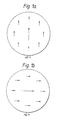
- the fundamental mode also referred to as the zero order mode
- the fundamental mode actually consists of two orthogonally polarised modes, both HE11. These are depicted in Figures 1a and 1b.
- the direction of the arrows in these Figures respectively indicate vertical polarisation for Figure 1a and horizontal polarisation for Figure 1b.
- the arrow at the centre of each of these two figures is larger than those disposed around it to indicate that the field is greatest at the centre.
- these two modes propagate with equal velocity, and so may be combined to produce any arbitrary pair of orthogonally polarised modes, such as left- and right-handed circularly polarised modes, or two orthogonal elliptically polarised modes.
- first order modes There are four true first order modes, namely TE01, TM01 and odd and even HE21.
- the pair of HE21 modes are degenerate in the same way as the pair of HE11 modes, but the three different types of first order mode TE01, TM01 and HE21 generally propagate with slightly differing velocities.
- the TE01 and TM01 modes both have annular circularly symmetric field distribution, which are respectively tangential and radial, and are depicted in Figures 2a and 2b.
- a circularly polarised HE11 field may be excited by superimposing the two orthogonally polarised linear HE11 modes in phase quadrature.
- the resultant is a field vector rotating at the optical frequency in a clockwise or anti-clockwise direction according to whether the phase of the second mode leads or lags the first.
- This circularly polarised HE11 field is depicted in Figure 3.
- the straight arrows indicate the field direction at a particular instant in time. It will be noticed that all the straight arrows are parallel, indicating that the field direction is the same over the whole area of the mode.
- the circular arrows indicate a clockwise progression of the field direction.
- a circularly polarised, circularly symmetric, first order field distribution is obtained by superimposing the TE01 and TM01 modes in phase quadrature.
- the instantaneous field direction is not the same all round the annulus, but is at progressively different directions around the annulus so that at any instant any given field direction occurs just once around the annulus.
- the polarisation of Figure 4 is the same as that of Figure 3, since both are clockwise (right-handed) circular.
- the resultant intensity distribution of Figure 5 results from a superimposing of zero order and first order fields of similar circular polarisation.
- Another way in which it may be provided is by the superimposing of zero order and first order fields of linear polarisation.
- the zero order field is that of one of the LP01 modes which are virtually identical with the HE11 modes, while the first order field is produced by superimposing similarly oriented complementary linearly polarised hybrid modes LP11 in phase quadrature.
- Figures 6a and 6b depict the two complementary hybrid LP11 modes.
- the intensity distribution of both of these first order hybrid modes consists of two spots 60 in which the electric field is oppositely directed at any instant along a single axis which remains fixed.
- an optical coherent detection system with phase diversity embodying the present invention in a preferred form consists essentially of an optical fibre mixing element constituted by coupler 90 and a multi-element, preferably a multisegment, photodetector 91.
- the coupler is provided with two input ports 92 and 93.
- One signal is launched into port 92 to propagate through the coupler 90 to reach the photodetector as a zero order field with a particular polarisation.
- the other signal is correspondingly launched into port 93 to reach the photodetector as a first order field with the same polarisation as that of the first-mentioned signal.
- a feature of this configuration is that the alignment of the coupler 90 with respect to the photodetector 91 may be simply achieved by exciting only one of the inputs to the coupler so as to provide it with a circularly symmetric output, and adjusting for equal output from each of the segments of the photodetector.
- the coupler 90 has been represented as a three-port device because only three ports are required.
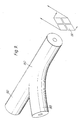
- a convenient way of implementing the required coupler is in the form of a fused fibre tapered directional coupler which has been constructed from two fibres and has four ports. In this case both input ports are used, but only one of the output ports. Typically the unused output port is terminated with an attenuator pad to prevent problems from reflections.
- Such a coupler may be constructed from a pair of identical fibres.
- Figure 10 schematically illustrates such a coupler constructed from identical fibres 100 and 101. The signal providing the requisite zero order field at the detector is launched into fibre 100 while that providing the requisite first order field is launched into fibre 101.
- the coupler may be of the kind in which the tapering is only just sufficient to produce total coupling of the first order field from fibre 101 to fibre 100 while leaving the more tightly bound zero order modes substantially uncoupled. Under these circumstances the requisite output is provided at the far end of fibre 100, while the far end of fibre 101 is unused and hence is shown in the drawing in broken outline.
- the tapering can be stronger and adjusted to provide that the zero order field couples from one fibre to the other n times while the first order couples (n+1) times. If n is an odd integer the principles of the output ends of the two fibres are of course reversed.
- a convenient way of providing the requisite first order field at the input end of fibre 101 is to precede this point with a length 102 of fibre into which a zero order field is launched which is mode converted in that length, for instance by periodic deformation introduced by pressing the fibre against mechanical gratings.
- a length 102 of fibre into which a zero order field is launched which is mode converted in that length, for instance by periodic deformation introduced by pressing the fibre against mechanical gratings.
- two gratings 103, 104 are employed spaced apart the requisite distance to give the appropriate phase relations at the detector between the respective components of the first order field.
- Adjustment of phase may alternatively be achieved by local deformations induced by fibre loops (not shown). Such use of loops will also normally be the most convenient way of providing the requisite adjustment of phase for the zero order power launched into fibre 100.
- Relative phase adjustment of the components of the first order field may alternatively or additionally be made by cutting back the output arm of the coupler in order to make use of the dispersion it provides to these components
- the coupler of Figure 10 is required to be capable of transmitting first order modes and hence it would superficially appear that it should not be constructed of single mode fibre.
- nominally single mode fibre is also capable of supporting first order modes, though with a greater attenuation than that afforded to the HE11 modes, this greater value being such that it effectively extinguishes the first order modes in a distance of no more than a few tens of metres.
- Such fibre is therefore in fact suitable for use in the construction of the coupler provided that the distance between the input and output ports from the coupling region of the coupler is kept reasonably short.
- it may be constructed from fibre that has been specifically prepared as overmoded "single mode" fibre by choice of single mode fibre designed for a longer operating wavelength or by not drawing it down from preform to quite the extent required to achieve single mode operation.
- the 4-port coupler of Figure 11 is distinguished from that of Figure 10 in that two fibres 110 and 111 from which it is constructed are not identical, but are chosen so that in the coupling region the phase velocity of the zero order field propagating in fibre 111 is matched with that of the first order field propagating in fibre 110.
- This may be achieved with fibres of the same core size and the same core/cladding refractive index difference if the refractive index of the core of fibre 110 is an appropriate amount greater than that of fibre 111.
- this may be achieved with fibres with matching core refractive indices and matching cladding refractive indices if the core diameter of fibre 111 is made an appropriate smaller than that of fibre 110.
- the match in phase velocity means that optical power propagating in the zero order field in fibre 111 is coupled into optical power propagating in a first order field in fibre 110 by virtue of the overlapping of these fields in the coupling region.
- Optical power in zero order fields is therefore launched into the input ends of both fibres 110 and 111 to provide an output from fibre 110 consisting of a mixture of zero order field derived from its own input and first order field derived from the zero order input to the other fibre.
- the appropriate phase relationships to produce the requisite similar polarisations can be provided by the adjustment of the deformations introduced by the presence of fibre loops (not shown) on the input side of the coupling region.
- relative phase adjustment of the components of the first order field may alternatively or additionally be made by cutting back the output arm of the coupler in order to make use of the dispersion it provides to these components.
- the mixing of the zero order and first order identically polarised fields at the multisegment detector is designed to produce an intensity distribution for which any change in phase of one of the fields with respect to that of the other produces solely a change in orientation of that intensity distribution. Attention is now directed to how a multisegment photodetector may be used to provide electrical signals for processing to produce a phase independent electrical signal output.
- the multisegment photodetector could have any number of segments, for instance it could be a six-sector array whose outputs can be processed in diametrically opposed pairs to produce output signals separated in phase by 120°.
- the preferred format of array is a quadrant photodetector because this shares the optical power between fewer receivers, each of which generates its own noise, and because the four outputs of a quadrant detector can be processed in diametrically opposed pairs to produce in-phase and phase quadrature outputs respectively.
- Such signals of the form A cos ⁇ and A sin ⁇ can be squared and summed to provide a final output signal that is independent of phase angle ⁇ .
- Each quadrant of the photodetector may be connected to its own low noise amplifier; however, it is generally preferred to connect the quadrants in diagonal pairs to two differential amplifiers as this provides a reduction in overall amplifier noise and hence an increased sensitivity provided that the effective responsivities can be accurately matched.
- Such matching is readily obtainable by exciting only one of the inputs to the coupler in order to produce a circularly symmetric intensity distribution across the surface of the photodetector and adjusting its position until all four quadrants produce identical photocurrents.
- a different processing algorithm may be employed alternatively or additionally to the above described one for producing a phase invariant signal, for instance one to produce a signal which characterises changes in relative phase.
- Such an algorithm is described for instance in the previously referenced Stowe and Hsu paper.
- the difference signals produced from the two diagonally opposed pairs of quadrants are each multiplied with the derivative with respect to time of the other difference signal, and then one of these resulting signals is subtracted from the other.
- Figure 9 has shown the light as being detected upon the segments of a quadrant photodetector and hence it is at the surface of these segments that the phase of the components of each field have to be related in the way necessary to provide that field with the requisite polarisation.
- the elements of the detector may not be the segments of a multisegment photodetector but may be spaced apart in a different configuration which may involve such greater separation between the elements. In such circumstances the light will be guided separately to each element.
- a heterodyne system In a heterodyne system the relative phase of the signals applied to the two input ports is continually changing, and so the asymmetric intensity distribution is amplitude modulated at the beat frequency. From this it also follows that in a heterodyne system the application of two orthogonal linearly polarised HE11 mode signals in phase quadrature to the first input port will produce two asymmetric intensity distributions that are amplitude modulated in phase quadrature at the beat frequency. In other words the system is responsive to any polarisation state of HE11 modes input, and is capable of distinguishing between such states.
- first order mode TE01 or TM01 for a polarisation sensitive coherent detection system is generated by induced mode coupling from an HE11 mode it may not always be convenient to arrange for only one of these two first order modes to be excited to the exclusion of the other. In fact this is not a problem provided that they are in phase with each other at the point where these modes are coherently mixed with the other HE11 mode.
- the situation is therefore somewhat analogous that of phase diversity system but, whereas in the phase diversity system phase quadrature is required and can be obtained but cutting back the fibre to the appropriate length, in the polarisation diversity system such cutting back will be to a point where the two first order mode signals are in phase with each other.
- the polarisation direction at points around the annulus of the combined first order TE01 and TM01 modes is neither exactly radial nor exactly tangential, but lies somewhere in between.
- the coherent detection system with polarisation diversity does not have phase diversity and hence, as mentioned before, there is of course no interference effect whenever the two interfering signals are in phase quadrature. This means that in a heterodyne detection system the asymmetric pattern generated by the interference effect is amplitude modulated at the beat frequency. In a homodyne detection system it means that other steps have to be taken to avoid a permanent phase quadrature condition persisting.
- Algorithms for processing the electrical signal outputs of the four quadrants of the photodetector in this polarisation diversity system may correspond with those employable in the phase diversity system.
- algorithms that in the phase diversity system produce outputs that are independent of phase and that are representative of the rate of change of phase in this polarisation diversity system produce outputs that respectively are independent of the state of polarisation of the zero order mode optical signal and representative of the rate of change of its state of polarisation.
Landscapes
- Physics & Mathematics (AREA)
- Electromagnetism (AREA)
- Engineering & Computer Science (AREA)
- Computer Networks & Wireless Communication (AREA)
- Signal Processing (AREA)
- Optical Transform (AREA)
- Optical Communication System (AREA)
- Gyroscopes (AREA)
- Light Guides In General And Applications Therefor (AREA)
Applications Claiming Priority (2)
| Application Number | Priority Date | Filing Date | Title |
|---|---|---|---|
| GB08619080A GB2193610A (en) | 1986-08-05 | 1986-08-05 | Coherent mixing of optical signals |
| GB8619080 | 1986-08-05 |
Publications (2)
| Publication Number | Publication Date |
|---|---|
| EP0256647A2 true EP0256647A2 (de) | 1988-02-24 |
| EP0256647A3 EP0256647A3 (de) | 1990-03-28 |
Family
ID=10602243
Family Applications (1)
| Application Number | Title | Priority Date | Filing Date |
|---|---|---|---|
| EP87305947A Ceased EP0256647A3 (de) | 1986-08-05 | 1987-07-06 | Kohärente Mischung von optischen Signalen |
Country Status (4)
| Country | Link |
|---|---|
| US (1) | US4898443A (de) |
| EP (1) | EP0256647A3 (de) |
| JP (1) | JPS63106707A (de) |
| GB (2) | GB2193610A (de) |
Cited By (1)
| Publication number | Priority date | Publication date | Assignee | Title |
|---|---|---|---|---|
| EP0576060A1 (de) * | 1992-06-25 | 1993-12-29 | Koninklijke KPN N.V. | Optische Mischeranordnung mit Photodetektor für einen Hétérodynempfänger |
Families Citing this family (4)
| Publication number | Priority date | Publication date | Assignee | Title |
|---|---|---|---|---|
| US5247309A (en) * | 1991-10-01 | 1993-09-21 | Grumman Aerospace Corporation | Opto-electrical transmitter/receiver module |
| US20020170591A1 (en) * | 2001-05-15 | 2002-11-21 | Pharmaseq, Inc. | Method and apparatus for powering circuitry with on-chip solar cells within a common substrate |
| WO2015023255A1 (en) | 2013-08-12 | 2015-02-19 | Halliburton Energy Services, Inc | Systems and methods for spread spectrum distributed acoustic sensor monitoring |
| WO2016033192A1 (en) | 2014-08-28 | 2016-03-03 | Adelos, Inc. | Noise management for optical time delay interferometry |
-
1986
- 1986-08-05 GB GB08619080A patent/GB2193610A/en not_active Withdrawn
-
1987
- 1987-04-24 GB GB8709777A patent/GB2193611B/en not_active Expired - Fee Related
- 1987-07-06 EP EP87305947A patent/EP0256647A3/de not_active Ceased
- 1987-08-04 JP JP62193881A patent/JPS63106707A/ja active Pending
-
1988
- 1988-12-19 US US07/289,396 patent/US4898443A/en not_active Expired - Lifetime
Non-Patent Citations (3)
| Title |
|---|
| ELECTRONICS LETTERS, vol. 21, no. 19, 12th September 1985, pages 867-868, Stevenage, Herts, GB; T.G. HODGKINSON et al.: "Demodulation of optical DPSK using in-phase and quadrature detection" * |
| IEE PROCEEDINGS SECTION A à I, Stevenage, October 1985, vol. 132, no. 5, Part J, October 1985, pages 277-286, Stevenage, Herts, GB; R.C. YOUNGQUIST et al.: "All-fibre components using periodic coupling" * |
| JOURNAL OF LIGHTWAVE TECHNOLOGY, vol. LT-1, no. 3, September 1983, pages 519-523, IEEE, New York, US; D.W. STOWE et al.: "Demodulation of interferometric sensors using a fiber-optic passive quadrature demodulator" * |
Cited By (1)
| Publication number | Priority date | Publication date | Assignee | Title |
|---|---|---|---|---|
| EP0576060A1 (de) * | 1992-06-25 | 1993-12-29 | Koninklijke KPN N.V. | Optische Mischeranordnung mit Photodetektor für einen Hétérodynempfänger |
Also Published As
| Publication number | Publication date |
|---|---|
| GB2193611B (en) | 1990-08-08 |
| GB8709777D0 (en) | 1987-05-28 |
| GB2193610A (en) | 1988-02-10 |
| US4898443A (en) | 1990-02-06 |
| GB8619080D0 (en) | 1986-09-17 |
| EP0256647A3 (de) | 1990-03-28 |
| GB2193611A (en) | 1988-02-10 |
| JPS63106707A (ja) | 1988-05-11 |
Similar Documents
| Publication | Publication Date | Title |
|---|---|---|
| EP0445943B1 (de) | Polarisationsunabhängige kohärente Lichtwellendetektionsvorrichtung | |
| Cole et al. | Synthetic-heterodyne interferometric demodulation | |
| US20100158521A1 (en) | Optical mixer for coherent detection of polarization-multiplexed signals | |
| CN105794129B (zh) | 偏振无关相干光接收器 | |
| EP1302774B1 (de) | Sagnac-interferometer-stromsensor | |
| US5200795A (en) | Passive quadrature phase detection system for coherent fiber optic systems | |
| GB2110895A (en) | Coherent detection and demodulation of a phase-modulated carrier wave in a random polarization state | |
| EP0642654A1 (de) | Konfigurationssteuerung von modekupplungsfehlern. | |
| EP0576663A1 (de) | Symmetrierung von Resonatorbetriebsarten. | |
| JPH03210841A (ja) | 光フアイバ通信システム | |
| Ohtsuka | Analysis of a fiber-optic passive loop-resonator gyroscope: Dependence on resonator parameters and light-source coherence | |
| JPS6387032A (ja) | 光信号ビーム検出装置 | |
| EP0246004B1 (de) | Optische Überlagerungsmischer mit Einzelfotodiode | |
| US4898443A (en) | Coherent mixing of optical signals | |
| Stowe et al. | Demodulation of interferometric sensors using a fiber-optic passive quadrature demodulator | |
| US20030169428A1 (en) | Saw tooth bias modulation and loop closure for an interferometric fiber optic gyroscope | |
| EP0260745A1 (de) | Vorrichtung zur optischen heterodynen Detektion eines optischen Signals und optisches Übertragungssystem mit einer solchen Vorrichtung | |
| EP0078931B1 (de) | Winkelgeschwindigkeitsfühler | |
| US5162869A (en) | Apparatus and method having at least one waveguide coupler to create at least two signals having a mutual phase shift not equal to 180 degrees | |
| US4609290A (en) | Passive homodyne demodulator and sensor system | |
| US5170275A (en) | Optical mixing for heterodyne detection | |
| EP0310174B1 (de) | Anordnung für optische Heterodyn- oder Homodyndetektion eines optischen Signalstrahls und Empfänger mit einer derartigen Anordnung | |
| WO1992005459A1 (en) | Optical apparatus | |
| WO1993005554A1 (en) | A method of suppressing relative intensity noise in coherent optical systems, such as communication receivers | |
| Travis et al. | Passive quadrature detection using speckle rotation on a multisegment photodetector |
Legal Events
| Date | Code | Title | Description |
|---|---|---|---|
| PUAI | Public reference made under article 153(3) epc to a published international application that has entered the european phase |
Free format text: ORIGINAL CODE: 0009012 |
|
| AK | Designated contracting states |
Kind code of ref document: A2 Designated state(s): BE DE FR IT NL SE |
|
| PUAL | Search report despatched |
Free format text: ORIGINAL CODE: 0009013 |
|
| AK | Designated contracting states |
Kind code of ref document: A3 Designated state(s): BE DE FR IT NL SE |
|
| 17P | Request for examination filed |
Effective date: 19900219 |
|
| 17Q | First examination report despatched |
Effective date: 19920601 |
|
| STAA | Information on the status of an ep patent application or granted ep patent |
Free format text: STATUS: THE APPLICATION HAS BEEN REFUSED |
|
| 18R | Application refused |
Effective date: 19921121 |
|
| RIN1 | Information on inventor provided before grant (corrected) |
Inventor name: EPWORTH, RICHARD EDWARD Inventor name: BRICHENO, TERRY Inventor name: WRIGHT, STEPHEN |