EP0256689A2 - Hochspannungsgleichstromversorgung für die elektrische Schaltung eines Kraftfahrzeuges - Google Patents
Hochspannungsgleichstromversorgung für die elektrische Schaltung eines Kraftfahrzeuges Download PDFInfo
- Publication number
- EP0256689A2 EP0256689A2 EP87306549A EP87306549A EP0256689A2 EP 0256689 A2 EP0256689 A2 EP 0256689A2 EP 87306549 A EP87306549 A EP 87306549A EP 87306549 A EP87306549 A EP 87306549A EP 0256689 A2 EP0256689 A2 EP 0256689A2
- Authority
- EP
- European Patent Office
- Prior art keywords
- voltage
- phase
- low
- generator
- autotransformer
- Prior art date
- Legal status (The legal status is an assumption and is not a legal conclusion. Google has not performed a legal analysis and makes no representation as to the accuracy of the status listed.)
- Granted
Links
Images







Classifications
-
- H—ELECTRICITY
- H02—GENERATION; CONVERSION OR DISTRIBUTION OF ELECTRIC POWER
- H02J—ELECTRIC POWER NETWORKS; CIRCUIT ARRANGEMENTS OR SYSTEMS FOR SUPPLYING OR DISTRIBUTING ELECTRIC POWER; SYSTEMS FOR STORING ELECTRIC ENERGY
- H02J7/00—Circuit arrangements for charging or discharging batteries or for supplying loads from batteries
- H02J7/14—Circuit arrangements for charging or discharging batteries or for supplying loads from batteries for charging batteries from dynamo-electric generators driven at varying speed, e.g. on vehicle
- H02J7/1438—Circuit arrangements for charging or discharging batteries or for supplying loads from batteries for charging batteries from dynamo-electric generators driven at varying speed, e.g. on vehicle in combination with power supplies for loads other than batteries
Definitions
- the invention herein relates to a high DC voltage power supply adapted for incorporation within a motor vehicle electrical circuit of the low DC voltage type.
- the usual low DC voltage electrical circuit for a motor vehicle includes a storage battery for providing standby power at the low DC voltage, a generator driven by the vehicle engine and controlled by a voltage regulator for producing a low three-phase AC voltage, and a three-phase rectifier for converting the low three-phase AC voltage to the low DC voltage for charging the storage battery and for energizing other low DC voltage loads in the vehicle.
- a high power windshield heater element is one example of such a high DC voltage load.
- the present invention provides a high DC voltage power supply applicable to a motor vehicle electrical circuit of the above type and capable of advantageously energizing a high DC voltage load such as a high power window glass heater.
- a motor vehicle electrical circuit in accordance with the present invention is characterised by the features specified in the characterising portion of Claim 1.
- the high DC voltage power supply of the invention includes a three-phase autotransformer and a three-phase full-wave rectifier.
- the autotransformer is employed to transform the low three-phase AC voltage of the usual motor vehicle electrical circuit to a high three-phase AC voltage.
- the rectifier is employed to rectify the high three-phase AC voltage to provide a high DC voltage suitable for energizing a high DC voltage load.
- This arrangement has the advantage of leaving the usual low DC voltage electrical circuit intact and undisturbed, i.e., the autotransformer and rectifier of the high DC voltage power supply do not have any part in the generation of the low DC voltage.
- the autotransformer provides cost and efficiency advantages as compared to a transformer having independent primary and secondary windings.
- the high DC voltage load is ungrounded, i.e., neither terminal of the load is connected to circuit ground.
- the potential at one load terminal is above ground while the potential at the other load terminal is below ground.
- the voltage available for inadvertent discharge from either load terminal to ground is lower than if one terminal of the load was grounded.
- the voltage that would be available for inadvertent discharge to ground from the ungrounded terminal of the load could be up to approximately twice the voltage available for inadvertent discharge with the invention.
- the invention reduces the chance for, and severity of, any electrical shock or arc that might be attendant to an accidental voltage discharge.
- This feature of the invention is especially advantageous where the high DC voltage necessary to satisfactorily energize the high DC voltage load is several times (or more) greater than the low DC voltage, as can be the case when the high DC voltage load is a high power window glass heater.
- control apparatus or applying means for selectively applying the low three-phase AC voltage to the autotransformer only when it is desired to energize the high DC voltage load. At all other times, the low three-phase AC voltage is withheld from the autotransformer to avoid incurring the energy losses and inefficiencies associated with energization of the autotransformer.
- This feature of the invention is particularly advantageous in a motor vehicle where reduced energy consumption and greater efficiency translate into increased vehicle fuel economy.
- the control apparatus is provided by one or more sets of switches located between the output of the generator and the input or primary side of the autotransformer, which is the low voltage/high current side of the voltage step-up autotransformer of the invention.
- the invention runs counter to usual electrical design practice which dictates that switching can be most easily and conveniently accomplished on the high voltage/low current side of a transformer, which would be the output or secondary side of the voltage step-up autotransformer of the invention.
- the autotransformer has at least first and second sets of input taps for providing different voltage step-up ratios dependent upon whether the low three-phase AC voltage is applied to the first set of taps or the second set of taps. In conjunction with the rectifier, this results in the provision of two high DC voltages having different absolute magnitudes. Additional sets of input taps can be employed to achieve additional voltage step-up ratios and additional high DC voltage levels.
- the high DC voltage load is a high power windshield heater element of the type where the heater resistance is in the form of a transparent film or layer uniformly distributed within or over the window glass.
- the two high DC voltages of different magnitude can be utilized to selectively produce maximum power and reduced power energization of the windshield heater element corresponding to deice and defog modes of operation, respectively.
- the tapping of the autotransformer on the input or primary side rather than the output or secondary side yields the most efficient design and operation of the autotransformer.
- the full phase winding of the autotransformer is utilized on the transformer secondary winding for all voltage step-up ratios.
- output or secondary taps were employed, less than the full phase winding of the autotransformer would be utilized as the transformer secondary winding tor all voltage step-up ratios less than the highest step-up ratio. For a given generator power output capability, this would require that the autotransformer have more core material and/or winding turns, i.e., be heavier and/or larger, than is required with the input or primary tapping arrangement of the present invention.
- the generator is excited from a voltage source independent of the low three-phase AC voltage put out by the generator (i.e., the generator is not self-excited), at least during any period that the combined power requirement imposed by the high DC voltage load and the low DC voltage loads would overload the generator and cause a degenerative collapse in the low three-phase AC voltage if the generator was excited from a voltage source dependent upon the low three-phase AC voltage.
- a voltage regulator which applies current to the generator field winding derived from the storage battery.
- the invention further contemplates, as an additional feature if desired, the provision of a current sensor, preferably a current transformer, for measuring the magnitude of the AC current through one of the input or output terminals of the autotransformer as an indication of the magnitude of the DC current through the high DC voltage load.
- a current sensor preferably a current transformer
- the terminals of the autotransformer are particularly advantageous for this purpose because they are readily accessible and because the AC current flow therethrough is proportional to the DC current flow through the high DC voltage load only and not any other vehicle loads.
- the high DC voltage load is the resistance element of a high-power windshield heater
- the current sensor can be employed to determine whether the sensed autotransformer current is below a lower limit indicative of an abnormally low load current such as might be caused by an opened condition in the heater element due to a cracked windshield.
- the invention also contemplates, as another optional feature, the provision of two capacitors each connected between a different associated one of the load terminals and circuit ground for suppressing radio frequency interference generated within the three-phase full-wave rectifier of the high DC voltage power supply.
- Part I is generally directed to an exemplary vehicle electrical circuit of the low DC voltage type to which the instant invention is particularly applicable.
- Part II is generally directed to the high DC voltage power supply aspects of the invention.
- Part III is generally directed to the dual mode heated windshield control aspects of the invention.
- Part IV is generally directed to digital computer implementations of the dual mode heated windshield control aspects of the invention.
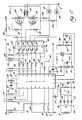
- Figure 1 includes an automotive vehicle electrical circuit 10 of the low DC voltage type.
- a storage battery 12 provides standby power at the low DC voltage, e.g., a nominal magnitude of fourteen volts.
- the positive terminal of the storage battery 12 is connected to a DC power line 14 while the negative terminal of the storage battery 12 is connected to circuit ground 16.
- circuit ground 16 Also connected between the DC power line 14 and circuit ground 16, through normally open contact 18 which may be part of the vehicle ignition switch, are various low DC voltage loads collectively represented by block 20.
- the low DC voltage loads 20 would normally include such things as the starter motor, vehicle lights, radio, electrical instruments, cigarette lighter, power door locks, power seat adjusters, power window operators, and the like.
- the electrical circuit 10 also includes a three-phase AC generator 22 having stationary output windings or phase windings 24a, 24b and 24c and a rotatable field winding 26 mechanically driven by the vehicle engine 28.
- a low three-phase AC voltage is developed across the phase windings 24a, 24b, and 24c having an amplitude determined by the amount of current fed through the rotatable field winding 26 and having a frequency determined by the rotating speed of the rotatable field winding 26.
- the low three-phase AC voltage is carried by AC power lines 30a, 30b and 30c.
- a rectifier 32 of the three-phase full wave bridge type includes positively poled diodes 34a, 34b and 34c connected between the AC power lines 30a, 30b and 30c, respectively, and the DC power line 14.
- the rectifier 32 further includes negatively poled avalanche diodes 36a, 36b and 36c connected between the AC power lines 30a, 30b and 30c, respectively, and circuit ground 16.
- the rectifier 32 is responsive to the low three-phase AC voltage put out by the three-phase AC generator 22 via the AC power lines 30a, 30b and 30c to rectify the same to provide a low DC voltage, between the DC power line 14 and circuit ground 16, for charging the storage battery 12 and supplying the various low DC voltage loads 20 of the automotive vehicle.
- a voltage regulator 38 is responsive to the magnitude of the low DC voltage put out by the rectifier 32 between the DC power line 14 and circuit ground 16 to regulate the amount of current fed from the storage battery 12 through the rotatable field winding 26 of the three-phase AC generator 22 to cause the amplitude of the low three-phase AC voltage to be correct to produce a low DC voltage of the desired magnitude, e.g., nominally fourteen volts, between the DC power line 14 and circuit ground 16 upon rectification by the rectifier 32.
- the voltage regulator 38 is of the type shown in U.S. patent 3,098,964 or U.S. patent 4,636,706 which are incorporated herein by reference.
- the automotive vehicle electrical circuit 10 is of common type and is shown by way of illustration only and not by way of any limitation upon the invention.
- the three-phase AC generator 22 may take other well-known forms effective to provide the required low three-phase AC voltage.
- the present invention provides a high DC voltage power supply for an automotive vehicle effective to advantageously energize a high DC voltage load such as a high-power windshield heater.
- a high DC voltage load 40 which may be a high-power windshield heater of the kind previously described, is schematically depicted as an ungrounded resistance.
- a high DC voltage power supply for energizing the high DC voltage load 40 includes a three-phase autotransformer 42, a three-phase full-wave bridge rectifier 44, and a pair of switching relays 46 and 48.
- the three-phase autotransformer 42 includes phase windings 50a, 50b and 50c connected in a wye configuration having an ungrounded neutral node or terminal at 52.
- the phase windings 50a, 50b and 50c are equipped with a first set of input terminals or taps 54a, 54b, and 54c, a second set of input terminals or taps 56a, 56b, and 56c, and a set of output terminals 58a, 58b, and 58c.
- the three-phase autotransformer 42 responds to the application of the low three-phase AC voltage put out by the three-phase AC generator 22 to step up the amplitude of the same to provide a high three-phase AC voltage at the output terminals 58a, 58b, and 58c.
- the application of the low three-phase AC voltage to the first set of input terminals 54a, 54b, and 54c results in the development of a first high three-phase AC voltage at the output terminals 58a, 58b, and 58c while the application of the low three-phase AC voltage to the second set of input terminals 56a, 56b, and 56c results in the development of a second high three-phase AC voltage at the output terminals 58a, 58b, and 58c.
- phase windings 50a, 50b and 50c of the three-phase autotransformer 42 each serve the dual function of a primary winding and a secondary winding.
- the primary winding is formed by the length of the phase winding 50a between the input terminal 54a and the neutral node 52 while the secondary winding is formed by the entire length of the phase winding 50a between the output terminal 58a and the neutral node 52.
- the turns ratio or voltage transformation ratio between the primary and secondary lengths of the phase winding 50a is such as to provide a step-up in voltage, i.e., the amplitude of the AC voltage developed between the output terminal 58a and the neutral node 52 is greater than the amplitude of the voltage applied between the input terminal 54a and the neutral node 52.
- the remaining two phase windings 50b and 50c are such as to provide a step-up in voltage, i.e., the amplitude of the AC voltage developed between the output terminal 58a and the neutral node 52 is greater than the amplitude of the voltage applied between the input terminal 54a and the neutral node 52.
- the step-up voltage transformation ratio provided by the three-phase autotransformer 42 between the first set of input terminals 54a, 54b, and 54c and the output terminals 58a, 58b, and 58c is higher than the step-up voltage transformation ratio provided between the second set of input terminals 56a, 56b, and 56c and the output terminals 58a, 58b and 58c.
- the amplitude of the first high three-phase AC voltage is greater than the amplitude of the second high three-phase AC voltage.
- the three-phase autotransformer 42 provides cost, size and efficiency advantages as compared to a transformer having separate, isolated primary and secondary windings. These advantages are especially significant in the automotive vehicle context of the invention where cost, size and efficiency are vital concerns.
- the three-phase full-wave bridge rectifier 44 includes positively poled diodes 60a, 60b and 60c connected between the output terminals 58a, 58b, and 58c, respectively, of the three-phase autotransformer 42 and one load terminal 62 of the high DC voltage load 40.
- the three-phase full-wave bridge rectifier 44 further includes negatively poled diodes 64a, 64b and 64c connected between the output terminals 58a, 58b, and 58c, respectively, of the three-phase autotransformer 42 and the other load terminal 66 of the high DC voltage load 40.
- the three-phase full-wave bridge rectifier 44 is responsive to the first and second high three-phase AC voltages appearing at the output terminals 58a, 58b, and 58c of the three-phase autotransformer 42 to rectify the same to provide corresponding first and second high DC voltages across the high DC voltage load 40 between the ungrounded load terminals 62 and 66. Consistent with the difference in amplitude between the first and second high three-phase AC voltages, the magnitude of the first high DC voltage is greater than the magnitude of the second high DC voltage.
- Capacitors 68 and 70 are connected between circuit ground 16 and the load terminals 62 and 66, respectively, to provide appropriate suppression of radio frequency interference (RFI) emanating from the diode switching action taking place in the three-phase full-wave bridge rectifier 44. Similar RFI suppression capacitors may be provided at other points in the circuit if desired, for example, between the AC power lines 30a, 30b and 30c, respectively, and circuit ground 16.
- RFID radio frequency interference
- the pair of switching relays 46 and 48 control the application of the low three-phase AC voltage from the three-phase AC generator 22 to the three-phase autotransformer 42.
- the first switching relay 46 includes a coil 72 which is effective when energized to close contacts 74a, 74b and 74c which are normally open to apply the low three-phase AC voltage from the AC power lines 30a, 30b and 30c of the three-phase AC generator 22 to the first set of input terminals 54a, 54b, and 54c of the three-phase autotransformer 42, respectively.
- the second switching relay 48 includes a coil 76 which is effective when energized to close contacts 78a, 78b and 78c which are normally open to apply the low three-phase AC voltage from the AC power lines 30a, 30b and 30c of the three-phase AC generator 22 to the second set of input terminals 56a, 56b, and 56c of the three-phase autotransformer 42, respectively.
- the three-phase autotransformer 42 and three-phase full-wave bridge rectifier 44 are effective to transform and rectify the low three-phase AC voltage put out by the three-phase AC generator 22 to provide a high DC voltage at a first or upper level between the load terminals 62 and 66 to energize the high DC voltage load 40 at high (maximum power.
- the three-phase autotransformer 42 and three-phase full-wave bridge rectifier 44 are effective to transform and rectify the low three-phase AC voltage put out by the three-phase AC generator 22 to provide a high DC voltage at a second or lower level between the load terminals 62 and 66 to energize the high DC voltage load 40 at low (reduced) power.
- the invention contemplates an appropriate controller 80 which, in its most rudimentary form, may be provided by a manually operable switch 82 including a movable contact 84 and three fixed contacts 86, 88 and 90 corresponding to off, maximum power and reduced power positions, respectively, of the manually operable switch 82.
- the movable contact 84 is connected to the DC power line 14.
- the fixed contact 86 is unconnected while the fixed contacts 88 and 90 are connected to the coils 72 and 76, respectively.
- the movable contact 84 In the maximum power position of the manually operable switch 82, the movable contact 84 is in engagement with the fixed contact 88 and the switching relay 46 is activated to initiate and sustain the maximum (high) power mode of operation in which the high DC voltage load 40 is energized by the first high DC voltage. In the reduced power position of the manually operable switch 82, the movable contact 84 is in engagement with the fixed contact 90 and the switching relay 48 is activated to initiate and sustain the reduced (low) power mode of operation in which the high DC voltage load 40 is energized by the second high DC voltage.
- the movable contact 84 In the off position of the manually operable switch 82, the movable contact 84 is in engagement with the unconnected fixed contact 86 to deactivate the switching relays 46 and 48 and thereby terminate and prohibit further energization of the high DC voltage load 40 in either the maximum (high) power mode or the reduced (low) power mode.
- the high DC voltage load 40 is depicted as a resistance having ungrounded load terminals 62 and 66.
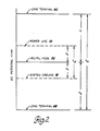
- the high DC voltage developed across the high DC voltage load 40 is symmetrical with respect to the potential at the neutral node 52 of the three-phase autotransformer 42.
- the potential at the load terminal 62 and the potential at the load terminal 66 are equally above and below the potential at the neutral node 52 of the three-phase autotransformer 42, respectively.
- the neutral node 52 of the three-phase autotransformer 42 is at the same potential as the imaginary neutral of the three-phase AC generator 22 which is approximately equivalent to one-half the nominal magnitude of the low DC voltage of the electrical circuit 10, or one-half the potential between the DC power line 14 and circuit ground 16.
- V HI is the DC voltage developed across the high DC voltage load 40 between the load terminals 62 and 66.
- V1 is the DC voltage appearing between the neutral node 52 of the three-phase autotransformer 42 and the load terminal 62 of the high DC voltage load 40 and is equal to one-half V HI .
- V2 is the DC voltage appearing between the neutral node 52 of the three-phase autotransformer 42 and the load terminal 66 of the high DC voltage load 40 and is also equal to one-half V HI .
- V LO is the DC voltage developed between the DC power line 14 and circuit ground 16.
- V X is the DC voltage appearing between the DC power line 14 and the neutral node 52 of the three-phase autotransformer 42 and is equal to one-half V LO .
- V Y is the DC voltage appearing between circuit ground 16 and the neutral node 52 of the three-phase autotransformer 42 and is equal to one-half V LO .
- the high voltage V HI is depicted in Figure 2 as approximately three times greater than the low DC voltage V LO .
- the potential at load terminal 62 is above circuit ground 16 while the potential at load terminal 66 is below circuit ground 16. Accordingly, the voltage available for inadvertent discharge from either of the load terminals 62 and 66 to circuit ground 16 is substantially lower than would otherwise be the case in a vehicle electrical circuit where one of the load terminals 62 and 66 was grounded. For example, in the latter kind of vehicle electrical circuit, if the load terminal 66 was connected to circuit ground 16, the entire high DC voltage would be available at the ungrounded load terminal 62 for inadvertent discharge to circuit ground 16.
- This benefit of the invention can be very effective in lowering the chance for, and severity of, any electrical shock or arc attendant to an accidental voltage discharge.
- Another benefit of the present invention involves the provision of the switching relays 46 and 48 (or equivalents) to selectively apply the low three-phase AC voltage put out by the three-phase AC generator 22 to the three-phase autotransformer 42 only when it is desired to energize the high DC voltage load 40. At all other times, the switching relays 46 and 48 are effective to withhold the low three-phase AC voltage from the three-phase autotransformer 42 thereby avoiding the various energy losses that would otherwise be incurred if the three-phase autotransformer 42 were continuously energized.
- This benefit of the invention is particularly advantageous in a motor vehicle electrical circuit where reduced energy consumption translates into increased vehicle fuel economy.
- the switching relays 46 and 48 should be located on the high voltage/low current side of the three-phase autotransformer 42, which is the output or secondary side of a voltage step-up transformer such as the three-phase autotransformer 42.
- the present invention runs counter to the foregoing standard electrical design tenet.
- a still further benefit of the invention derives from placement of the first and second sets of voltage step-up ratio changing taps provided by input terminals 54a,b,c and 56a,b,c on the input or primary side of the phase windings 50a,b,c of the three-phase autotransformer 42 rather than the output or secondary side.
- the tap sets 54a,b,c and 56a,b,c as input or primary taps
- the full phase winding 50a,b,c of the three-phase autotransformer 42 is utilized as the transformer secondary winding for both voltage step-up ratios.
- output or secondary taps were employed, less than the full phase winding 50a,b,c would be utilized as the transformer secondary winding for the lower of the two voltage step-up ratios.
- Figure 3A illustrates the "primary side” transformer tapping and switching arrangement of the invention.
- Figure 3B illustrates the converse "secondary side” transformer tapping and switching arrangement.
- the illustration is confined to a single phase winding 50 of the three-phase autotransformer 42 including high power tap 54 and associated contact 74 and low power tap 56 and associated contact 78.
- the flux level ⁇ of the three-phase autotransformer 42 is inversely related to the product of the generator frequency F and the number of primary winding turns N. For maximum efficiency, it is desirable that this product be such as to maintain the flux level ⁇ at a maximum value ⁇ m which yields an operating point just below the saturation point of the B versus H operating curve of the three-phase autotransformer 42, where B is flux per unit area of the transformer core and H is ampere-turns per unit length of the transformer core.
- ⁇ m KE/FN
- FN KE/ ⁇ m where the quantity KE/ ⁇ m is a constant.
- the generator frequency F is determined by the combined power requirement of the high DC voltage load 40 and low DC voltage loads 20 in respect to the frequency versus power output curves of the three-phase AC generator 22.
- the lowest running frequency of the three-phase AC generator 22 is experienced at the lowest running speed of the vehicle engine 28, which is usually the warmed-up idle speed.
- the speed of the vehicle engine 28 must be controlled during the high-power mode of operation to drive the three-phase AC generator 22 at a higher frequency at which the generator output power is sufficient to meet the combined power requirement of the low and high DC voltage loads 20 and 40 during the high power mode of operation, or the three-phase AC generator 22 will be overloaded and the storage battery 12 will be discharged.
- the speed of the vehicle engine 28 need not be controlled during the low power mode of operation since any engine speed at or above the warmed-up idle speed will provide adequate output power from the three-phase AC generator 22 and the storage battery 12 will not be discharged.
- the speed of the vehicle engine 28 must be controlled during the low power mode of operation as well or the three-phase AC generator 22 will be overloaded and the storage battery 12 will be discharged.
- the first frequency F1 is the lowest generator frequency required for the high power mode of operation which typically will be greater than the warmed-up idle speed of the vehicle engine 28.
- the second frequency F2 is the lowest frequency suitable for the low power mode of operation, which may be the generator frequency corresponding to the warmed-up idle speed of the vehicle engine 28.
- the first turns number N1 is the number of primary winding turns necessary to satisfy expression (3) when the generator frequency is F1.
- the second turns number N2 is the number of primary winding turns necessary to satisfy expression (3) when the generator frequency is F2.
- the second number N2 of primary winding turns required for the low power mode is greater than the first number N1 of primary winding turns required for the high power mode by a factor F1/F2 which is the ratio of the first generator frequency F1 required for the high power mode to the second generator frequency F2 required for the low power mode.
- F1/F2 is the ratio of the first generator frequency F1 required for the high power mode to the second generator frequency F2 required for the low power mode.
- the ratio of primary turns to secondary turns for the high power mode is N1:N3 while the ratio of primary turns to secondary turns for the low power mode is N2:N3 where N3 is the total number of turns in the phase winding 50.
- the N3 number of winding turns is utilized for the high power mode at the higher generator frequency F1 and the amount of core material can accordingly be optimized for this high frequency.
- the N3 number of winding turns is utilized for the low power mode only at the lower generator frequency F2 and the amount of core material must accordingly be designed for this lower frequency. Therefore, the Figure 3B arrangement disadvantageously requires more core material in the three-phase autotransformer 42 than the Figure 3A arrangement for the same N3 number of winding turns.
- the N4-N3 number of turns of the phase winding 50 are not utilized during the low power mode of operation even though they are energized during such mode.
- the three-phase AC generator 22 is excited from a voltage source independent of the low three-phase AC voltage put out by the three-phase AC generator 22, i.e., the three-phase AC generator 22 is not self-excited.
- the voltage regulator 38 is of the type that energizes the rotatable field winding 26 of the three-phase AC generator 22 with a voltage derived from the storage battery 12 as opposed to a voltage derived from the output voltage of the three-phase AC generator 22.
- the rotatable field winding 26 was energized with a voltage derived from the low three-phase AC voltage put out by the three-phase AC generator 22, i.e., if the three-phase AC generator 22 was self-excited, the output voltage of the three-phase AC generator 22 would suffer a degenerative collapse. Specifically, at the onset of the overload condition, the output voltage of the three-phase AC generator 22 would decrease thereby producing a decrease in the voltage energizing the rotatable field winding 26 which would further decrease the output voltage of the three-phase AC generator 22 and so on until the output voltage of the three-phase AC generator 22 was fully collapsed.
- the voltage energizing the rotatable field winding 26 is maintained, at least so long as the charge of the storage battery 12 holds up, and the degenerative collapse of the low three-phase AC voltage put out by the three-phase AC generator 22 is prevented.
- the voltage regulator 38 could be of the type that otherwise energizes the rotatable field winding 26 with a voltage derived from the output voltage of the three-phase AC generator 22. Examples of such a voltage regulator are shown in U.S. patents 3,469,168 and 3,597,654 where the voltage for exciting the field winding is derived from the generator output voltage via a diode trio.
- An additional advantage of the invention resides in the fact that the normal operation of the automotive vehicle electrical circuit 10 to produce the usual low DC voltage between the DC power line 14 and circuit ground 16 is unaffected by the high DC voltage power supply provided by the invention, i.e., the three-phase autotransformer 42, three-phase full-wave bridge rectifier 44 and switching relays 46 and 48 do not interfere with, or have any part in, the generation of the usual low DC voltage. In this way, the efficiency and reliability of the low DC voltage circuit 10 are not degraded by the high DC voltage power supply of the invention.
- the input terminals 54a,b,c and 56a,b,c and the output terminals 58a,b,c of the three-phase autotransformer 42 provide convenient portals through which to monitor the AC current flow associated with the three-phase autotransformer 42 to obtain an indication of the corresponding DC current flow through the high DC voltage load 40.
- the present invention contemplates that the high DC voltage load 40 may be the resistance element of a motor vehicle windshield heater and the high DC voltage power supply (provided by the three-phase autotransformer 42, the three-phase full-wave bridge rectifier 44 and the switching relays 46 and 48) may be employed to selectively produce maximum and reduced i.e., high and low, heat outputs from the resistance element corresponding to deice and defog modes of operation, respectively.
- the high DC voltage load 40 may be the resistance element of a motor vehicle windshield heater and the high DC voltage power supply (provided by the three-phase autotransformer 42, the three-phase full-wave bridge rectifier 44 and the switching relays 46 and 48) may be employed to selectively produce maximum and reduced i.e., high and low, heat outputs from the resistance element corresponding to deice and defog modes of operation, respectively.
- the first switching relay 46 is energized to render the three-phase autotransformer 42 and the three-phase full-wave bridge rectifier 44 effective to develop the first high DC voltage at a maximum magnitude across the resistance element to produce a maximum heat output from the resistance element sufficient to remove ice and frost from the exterior surface of the vehicle windshield.
- the second switching relay 48 is energized to render the three-phase autotransformer 42 and the three-phase full-wave bridge rectifier 44 effective to develop the second high DC voltage at a reduced magnitude across the resistance element to produce a reduced heat output from the resistance element sufficient to remove condensation from the interior surface of the windshield and/or to help prevent the formation of ice or frost on the exterior surface of the windshield.
- the resistance of the resistance element may be on the order of 3.8 ohms
- the maximum power output from the resistance element during the deice mode of operation may be on the order of 1500 watts
- the reduced power output from the resistance element during the defog mode of operation may be on the order of 400 watts.
- the first high DC voltage of maximum magnitude is on the order of 75 volts while the second high DC voltage of reduced magnitude is on the order of 40 volts.
- the latter two high DC voltages are substantially greater than the magnitude of the low DC voltage, e.g., nominally fourteen volts, available in the usual automotive vehicle electrical circuit such as that designated by the numeral 10 in Figure 1.
- the invention contemplates a controller 80, as shown in Figure 4, which consists of appropriate control circuitry 92 and various associated inputs (to be described) providing a sophisticated array of control features as follows:
- the control circuitry 92 is operative to initiate the deice mode of operation in response to a vehicle operator actuated deice command, such as depression of momentary deice pushbutton switch 94, provided that the vehicle transmission 96 is in a park or neutral state (i.e., not in one of the drive states) as indicated by an appropriate sensor 98, which may be a switch responsive to the position of the transmission shift selector 100 such that the sensor 98 switch is closed when the vehicle transmission 96 is in the park or neutral state.
- a vehicle operator actuated deice command such as depression of momentary deice pushbutton switch 94
- an appropriate sensor 98 which may be a switch responsive to the position of the transmission shift selector 100 such that the sensor 98 switch is closed when the vehicle transmission 96 is in the park or neutral state.
- the control circuitry 92 is responsive to energize the coil 72 to initiate the deice mode of operation and, at the same time, to also energize a telltale device 102, which may be provided by a light emitting diode, to indicate that the deice mode of operation is in progress.
- a telltale device 102 which may be provided by a light emitting diode
- the control circuitry 92 is operative to automatically terminate the deice mode of operation a predetermined time period after initiation unless earlier terminated by action of the vehicle operator.
- the predetermined deice time period should be sufficiently long to satisfactorily clear ice and frost from the exterior surface of the windshield, e.g., two minutes where the maximum power output of the resistance element is of the order of 1500 watts.
- the deice mode of operation is immediately terminated.
- the deice mode of operation is also immediately terminated in response to a vehicle operator actuated off command, such as depression of momentary off pushbutton switch 104.
- the control circuitry 92 is effective to terminate the deice mode of operation by deenergizing the coil 72, at which time the deice telltale device 102 is also deenergized.
- the control circuitry 92 is operative to initiate the defog mode of operation automatically in response to termination of a preceding deice mode of operation, except where termination of such deice mode was effected by a vehicle operator actuated off command.
- This defog-after-deice feature keeps the resistance element energized at a reduced heat output immediately following the deice mode of operation to prevent the reformation of ice or frost on the exterior of the windshield.
- the control circuitry 92 is operative to initiate the defog mode of operation in response to a vehicle operator actuated defog command, such as depression of momentary defog pushbutton switch 106.
- the control circuitry 92 is responsive to energize the coil. 76 to initiate the defog mode of operation and, at the same time, to also energize a telltale device 108, which may be provided by a light emitting diode, to indicate that the defog mode of operation is in progress.
- control circuitry 92 is operative to automatically terminate the defog mode of operation a predetermined time period after initiation, provided that such initiation was in response to termination of an immediately preceding deice mode of operation.
- the predetermined defog time period should be sufficiently long to satisfactorily keep ice and frost from reforming on the exterior of the windshield until the usual hot air type windshield defroster and/or interior space heater of the vehicle have warmed up to a temperature effective to perform this function, i.e., ten minutes.
- the defog mode of operation is permitted to continue indefinitely until terminated in response to an operator actuated off command, i.e., depression of momentary off pushbutton switch 104.
- an operator actuated off command i.e., depression of momentary off pushbutton switch 104.
- the defog mode of operation can be utilized as a substitute for the usual hot air type windshield defroster, thereby eliminating the ductwork, blower motor, etc. normally associated with the latter.
- the control circuitry 92 is effective to terminate the defog mode of operation by deenergizing the coil 76, at which time the defog telltale device 108 is also deenergized.
- control circuitry 92 is responsive to initiation of the deice mode of operation to issue a fast idle command to the vehicle engine 28 via line 110 to raise the engine idle speed (and torque) above the normal idle speed (and torque) to ensure that the motive power provided by the vehicle engine 28 is great enough to drive the three-phase AC generator 22 at the speed or frequency required to produce the necessary electrical power for the deice mode of operation.
- the storage battery 12 could become undesirably discharged during the deice mode of operation, particularly where the size of the three-phase autotransformer 42 has been kept to the minimum necessary to provide sufficient power to satisfy the defog mode of operation when the vehicle engine 28 driving the three-phase AC generator 22 is running at idle speed.
- the operation of the vehicle engine 28 is governed by an electronic controller (not separately shown) of known type having apparatus for raising the idle speed of the vehicle engine 28 in response to receipt of a fast idle command from the control circuitry 92.
- the vehicle engine 28 could be specifically equipped with a suitable actuator to perform this function.
- the control circuitry 92 is operative to prohibit further energization of the resistance element in response to overheating of the vehicle windshield as is detected by a heat sensor 112 which may be a thermistor located in or on the windshield.
- a heat sensor 112 which may be a thermistor located in or on the windshield.
- overheating which might result in damage to the windshield, could occur if either the deice or defog mode of operation is inadvertently initiated in warm weather.
- the control circuitry 92 acts to immediately deenergize the energized one of the switching relays 46 and 48 thereby terminating whichever one of the deice and defog modes of operation happens to then be in progress.
- the control circuitry 92 senses the voltage of the storage battery 12 appearing between lines 114 and 116 and prohibits further energization of the resistance element, by deenergizing the energized one of the switching relays 46 and 48, if the battery voltage drops below a specified lower limit, e.g. eleven volts. This feature prevents the storage battery 12 from becoming inordinately discharged by operation of the resistance element.
- the lines 114 and 116 are electrically equivalent to the DC power line 14 and circuit ground 16 shown in Figure 1.
- control circuitry 92 is deenergized, thereby deenergizing the switching relays 46 and 48 and prohibiting further energization of the resistance element, whenever the (ignition switch) normally open contacts 18 are opened, i.e., when the vehicle ignition switch is shut off by the vehicle operator.
- a current transformer 118 senses the current flowing through one of the output terminals 58a, 58b and 58c of the three-phase autotransformer 42.
- the current transformer 118 could be applied to sense the current flow through one of the input terminals 54a, 54b and 54c or 56a, 56b and 56c of the three-phase autotransformer 42.
- the current transformer 118 includes a core 120 looped around a lead wire 122 connected to the output terminal 58a of the three-phase autotransformer 42 such that the lead wire 122 forms the primary winding of the current transformer 118.
- a secondary winding 124 is wound around core 120 and connected to the control circuitry 92. While the current transformer 118 is preferred, other forms of current detection could be employed instead.
- the AC current flowing through the lead wire 122 is related to, and indicative of, the DC current flowing through the high DC voltage load (resistance element) 40 (the DC load current is derived from the AC transformer current). If the windshield should become cracked, causing an open circuit condition through all or part of the resistance element, the DC load current through the resistance element will fall abnormally low thereby causing the AC current flow through the lead wire 122 to be likewise abnormally low. Under some circumstances, a cracked windshield condition could result in arcing if the resistance element remains energized. Accordingly, in the event of abnormally low AC transformer current, it is desirable that energization of the windshield heater be immediately terminated.
- control circuitry 92 monitors the current flow through the lead wire 122 via the secondary winding 124 and core 120 of the transformer 118 and deenergizes the switching relays 46 and 48 whenever this current flow is below a lower limit indicative of an abnormally low DC current flow in the resistance element.
- control circuitry 92 for providing the previously described control features may take a variety of well-known forms.
- the control circuitry 92 may be implemented using logic devices such as AND gates, OR gates, flip-flops, monostable multivibrators, inverters, comparators, latch devices and the like, all as well understood in the art.
- the control circuitry 92 can be implemented by a suitably programmed digital computer together with appropriate peripheral devices.
- Other suitable forms of the control circuitry 92 will also be apparent to the skilled artisan.
- the present invention is not limited to any particular implementation of the control circuitry 92.
- the control circuitry 92 shown in Figure 4 is implemented by a digital computer apparatus as shown in Figure 5 where like numerals are used to denote like elements.
- the digital computer 126 may be, for example, a Motorola Model No. MC6805R2 microcomputer commercially available from Motorola, Inc., as described in Motorola publication: "Advance Information, MC68(7)05R/U Series 8-Bit Microcomputers," pages 3-298 to 3-389. The latter publication is available upon request from Motorola, Inc., or from the applicant of this application. However, it is to be understood that the digital computer 126 can be implemented by any suitable digital computer.
- Pins 33,34,36,37 and 38 of the digital computer 126 are discrete inputs to the input/output unit of the digital computer 126.
- the pushbutton switch 94 for deice is connected between circuit ground 16 and pin 36 of the digital computer 126.
- the pushbutton switch 106 for defog is connected between circuit ground 16 and pin 38 of the computer 126.
- the pushbutton switch 104 for off is connected between circuit ground 16 and pin 37 of the digital computer 126.
- the sensor 98 for vehicle transmission is connected between circuit ground 16 and pin 34 of the digital computer 126.
- a bypass switch 128 (not previously described, but to be described hereinafter) is connected between circuit ground 16 and pin 33 of the digital computer 126.
- Pull-up resistors 130,132,134,136 and 138 are each connected between a six volt source 140 and the pins 33,34,36,37 and 38, respectively. In operation, the potential at pins 33,34,36,37 and 38 is shifted to ground when the associated one of the switches 94,98,104,106 or 128 is closed and is otherwise maintained at the six volt potential of six volt source 140 via pull-up resistors 130,132,134,136 and 138 when the associated one of the switches, 94, 98,104,106 and 128 is open.
- the six volt source 140 is connected directly to pin 4 and indirectly to pins 3,8 and 18 of the digital computer 126 through resistors 142,144 and 146 respectively.
- a clock reference for the digital computer 126 is provided by a 4MHz crystal 148 connected between pins 5 and 6, and a capacitor 150 connected between pin 5 and circuit ground 16.
- a five volt source 152 is connected directly to pin 19.
- Pins 1,7 and 20 are connected directly to circuit ground 16.
- a capacitor 154 is connected between pins 19 and 20.
- a capacitor 156 is connected between pins 1 and 2.
- Pins 22,23 and 24 of the digital computer 126 are analogue voltage inputs to the analogue to digital converter unit of the digital computer 126.
- pin 22 is connected to the junction between a pair of voltage divider resistors 112 and 158 connected in series between the five volt source 152 and circuit ground 16 where the resistor 112 is the heat sensor for the windshield.
- Noise and transient filtering is provided by capacitor 160 and which is connected between pin 22 and circuit ground 16. Accordingly, the windshield temperature sensor input appears as an analogue voltage at pin 22 of the digital computer 126.
- the secondary winding 124 of the (windshield crack detector) current transformer 118 is connected via a full-wave bridge rectifier 162 and voltage divider/filter 164 to pin 23 of the digital computer 126.
- the full-wave bridge rectifier 162 is provided by diodes 166,168,170 and 172.
- the voltage divider/filter 164 is provided by resistors 174 and 176 and by capacitor 178.
- pin 23 is connected to the junction between the resistors 174 and 176 which are connected in series between the positive terminal of the full-wave bridge rectifier 162 and the negative terminal of the full-wave bridge rectifier 162 which is connected to circuit ground 16.
- Capacitor 178 for noise and transient filtering is connected between pin 23 and circuit ground 16.
- the AC voltage developed across the secondary winding 124 of the (windshield crack detector) current transformer 118 is full-wave rectified by the full-wave bridge rectifier 162 to provided a DC voltage which is divided by the resistors 174 and 176 and applied to pin 23 of the digital computer 126 as the windshield crack detector input.
- Pin 24 of the digital computer 126 is connected to the junction between a pair of voltage divider resistors 180 and 182 which are connected in series across the storage battery 12. Noise and transient filtering is provided by a capacitor 184 connected between pin 24 and circuit ground 16. Reverse polarity voltage protection is provided by diode 186 connected between pin 24 and circuit ground 16. Thus, an analogue voltage proportioned to the vehicle battery voltage appears at pin 24 of the digital computer 126.
- Pins 27,32,35,39 and 40 of the digital computer 126 are discrete outputs from the input/output unit of the digital computer 126. Each discrete output is buffered through an NPN junction transistor connected in a common emitter configuration and provided as part of an integrated circuit buffer module 190 which may be a CA3081 as commercialy available from RCA Corporation.
- Pin 39 of the digital computer 126 is the fast idle discrete output.
- an NPN transistor 192 in the integrated circuit buffer module 190 is turned off through the biasing action of resistors 194 and 196 to send a fast idle command signal (high potential) to the vehicle engine 28 via a resistor 198 and line 110.
- Pins 35 and 40 of the digital computer 126 are the deice and defog relay outputs, respectively.
- an NPN transistor 200 in the integrated circuit buffer module 190 is turned on through the biasing action of resistors 202 and 204 to turn on a MOSFET driver transistor 206 to energize coil 72 for deice.
- an NPN transistor 208 in the integrated circuit buffer module 190 is turned on through the biasing action of resistors 210 and 212 to turn on an MOSFET driver transistor 214 to energize coil 76 for defog.
- MOSFET driver transistors 206 and 214 may, for example, be IRF9511 P-channel devices available from International Rectifier, Inc.
- Biasing resistors 216 and 218 are connected between a nominal twelve volt source 220 (which may be derived from the load side of the normally open contact 18 of vehicle ignition switch) and the gates of the MOSFET driver transistors 206 and 214, respectively, to keep the MOSFET driver transistors 206 and 214 turned off at all times other than when the NPN transistors 200 and 208 are turned on.
- a Diode 222 is connected from the base of NPN transistor 200 to the collector of NPN transistor 208 as an interlock to ensure that if the potential at pins 35 and 40 should be high at the same time NPN, transistor 208 will turn on and NPN transistor 200 will turn off thereby making the defog mode of operation the default mode of the circuit.
- Pins 27 and 32 of the digital computer 126 are the deice and defog indicator outputs, respectively.
- an NPN transistor 224 in integrated circuit buffer module 190 is turned on through the biasing action of resistors 226 and 228 to keep telltale device 102 for deice deenergized.
- an NPN transistor 230 in integrated circuit buffer module 190 is turned on through the biasing action of resistors 232 and 234 to keep telltale device 108 for defog deenergized.
- NPN transistor 224 When the potential at pin 27 of the digital computer 126 is low (during the deice mode), NPN transistor 224 turns off thereby permitting telltale device 102 to be energized through a resistor 236 which is connected to nominal twelve volt source 220. In like manner, when the potential at pin 32 is low (during the defog mode), NPN transistor 230 is turned off thereby permitting telltale device 108 to be energized through a resistor 240 which is connected to nominal twelve volt source 220.
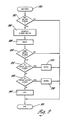
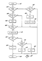
- the digital computer 126 shown in Figure 5 is operated in accordance with a program embodied within a set of flow charts illustrated in Figures 6-17.
- the main program is initiated at point 250 when power is first applied to the digital computer 126, e.g., when normally open contact 18 of ignition switch is closed.
- the program proceeds to an initialize step 252 where an initialize routine is executed as shown in Figure 7.
- the main program recirculates continuously through a loop consisting of a faults step 254 at which a faults routine is performed as shown in Figure 8, a switches step 256 at which a switches routine is performed as shown in Figure 9, and a timers step 258 at which a timers routine is performed as shown in Figure 10.
- the latter three steps 254,256 and 258 are repeatedly executed in series so long as the digital computer 126 is powered up.
- the initialize routine begins at point 260 and proceeds to an allow interrupt step 262 at which the internal interrupt timer in the central processing unit of the digital computer 126 is set and after which such timer repeatedly calls an interrupt routine as shown in Figure 11, e.g., every 25 milliseconds.
- the initialize routine proceeds to an off step 264 at which an off routine is executed as shown in Figure 12.
- the initialize routine proceeds to an end point 266 at which the routine is terminated.
- the interrupt routine establishes and operates the three timers utilized by the dual mode heated windshield control: a deice timer for timing the deice mode of operation, a defog timer for timing the timed defog mode of operation, and a crack detector delay timer for timing a delay following initial energization of the three-phase AC generator 22 before any cracked windshield indication is interpreted as valid.
- the latter delay permits the voltage regulator 38 to gradually bring the low three-phase AC voltage output of the three-phase AC generator 22 up to its full operating value sufficiently slowly that the increased load on the vehicle engine 28 is not noticeable to the vehicle operator.
- a typical value for this crack detector delay period may be approximately three seconds.
- typical values for the timed deice and defog modes of operation may be two minutes and ten minutes, respectively.
- the interrupt routine of Figure 11 begins at point 268 and proceeds to a set interrupt timer step 270 at which the interrupt timer in the central processing unit of the digital computer 126 is set.
- the routine then proceeds to a decision step 272 at which the digital computer 126 determines whether the count in the deice timer is zero, meaning that the timer is inactive. If the decision at decision step 272 is no, the program proceeds to a decision step 274 at which the digital computer 126 determines whether the count. in the deice timer is one. If the decision at decision step 274 is yes, a deice timer flag is set true at step 276 and the routine proceeds to a decrement deice timer step 278.
- step 274 If the decision of decision step 274 is no, the program immediately proceeds to the decrement deice timer step 278. At decrement deicer timer step 278, the deice timer is decremented one count and the routine then moves on to decision step 280. Similarly, if the decision at decision step 272 is yes, the interrupt routine proceeds immediately to decision step 280.
- the digital computer 126 determines whether the count in the defog timer is zero, meaning that the timer is inactive. If the decision at decision step 280 is no, the program proceeds to a decision step 282 at which the digital computer 126 determines whether the count in the defog timer is one. If the decision at decision step 282 is yes, a defog timer flag is set true at step 284 and the routine proceeds to a decrement defog timer step 286. If the decision of decision step 282 is no, the program immediately proceeds to the decrement defog timer step 286.
- defog timer is decremented one count and the routine then moves on to decision step 288. Likewise, if the decision at decision step 280 is yes, the interrupt routine proceeds immediately to decision step 288.
- the digital computer 126 determines whether the count in the crack detector delay timer is zero, meaning that the timer is inactive. If the decision at decision step 288 is no, the program proceeds to timer step 290. At timer step 290, the crack detector delay timer is decremented one count and the interrupt routine then proceeds to an end point 292 at which the routine is terminated. Similarly, if the decision at decision step 288 is yes, the routine proceeds immediately to the end point 292.
- the faults routine checks the heated windshield circuit for any problems or faults.
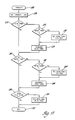
- the faults routine begins at point 294 and proceeds to a decision step 296 at which the digital computer 126 determines whether the battery voltage input at pin 24 indicates that the voltage of the storage battery 12 is below a lower limit, e.g., below eleven volts. If the decision at decision step 296 is yes, a fault flag is set true at step 298 and the faults routine proceeds to an oFf step 300 where an off routine is performed as shown in Figure 12. Following execution of the off step 300, the faults routine then proceeds to an end point 302 at which the routine is terminated.
- the faults routine moves on to a decision step 304 at which the digital computer 126 determines whether the crack detector input at pin 23 indicates that the windshield is cracked. If the decision at decision step 304 is yes, the program proceeds to a decision step 306 at which the digital computer 126 determines whether the count in the crack detector delay timer is zero, meaning that the timer is inactive or timed out. If the decision at decision step 306 is yes, the fault flag is set true at step 298 and the routine proceeds through steps 300 and 302 as previously described. If the decision at decision step 306 is no, the faults routine moves on to decision step 308. Similarly, if the decision at decision step 304 is no, the faults routine proceeds immediately to decision step 308.
- the digital computer 126 determines whether the windshield temperature input at pin 22 indicates that the windshield temperature is above an upper limit, e.g., above 38°C (100° F). If the decision at decision step 308 is yes, the program proceeds to a decision step 310 at which the digital computer 126 determines whether the bypass switch 128 is closed, i.e., whether pin 33 is at ground. The bypass switch 128 permits the windshield temperature input at pin 22 to be bypassed during manufacturing and maintenance operations. If the decision at decision step 310 is no, the fault flag is set true at step 298 and the program proceeds through steps 300 and 302 as previously described. If the decision at decision step 310 is yes, the program moves to a decision step 312. Likewise, if the decision at decision step 308 is no, the faults routine proceeds immediately to decision step 312.
- the digital computer 126 determines whether pin 34 is at ground potential indicating that the switch of sensor 98 is closed because the vehicle transmission 96 is in the park or neutral condition. If the decision at decision step 312 is yes, the fault flag is set false at step 314 and the fault routine proceeds to the end point 302. If the decision at decision step 312 is no, the program proceeds to decision step 316 at which the digital computer 126 determines whether the count in the deice timer is zero. If the decision at decision step 316 is yes, the program proceeds through steps 314 and 302 as previously described. If the decision at decision step 316 is no, the program proceeds to step 318 at which a timed defog routine is executed as shown in Figure 13, and then the faults routine proceeds through steps 314 and 302 as previously described.
- the switches routine monitors the condition of the deice, defog and off pushbutton switches 94, 104 and 106.
- the switches routine begins at point 320 and proceeds to a decision step 322 at which the digital computer 126 determines whether any of the pushbutton switches 94, 104 or 106 is closed as indicated by the potential at pins 36, 38 and 37, respectively. If the decision at decision step 322 is no, the switches routine proceeds immediately to an end point 324 at which the routine is terminated. If the decision at decision step 322 is yes, the program proceeds to step 326 at which the identity of the closed one of the pushbutton switches 94, 104 and 106 is saved in memory.
- step 328 a delay routine as shown in Figure 13 is executed.
- the switches routine proceeds to decision step 330 at which the digital computer 126 determines whether the previously identified one of the pushbutton switches 94, 104 and 106 is still closed as indicated by the potential at the appropriate one of the pins 36, 38 and 37.
- the step 328 delay which may be on the order of 10 milliseconds, provides for clearance of a false "switch closed" indication due to noise, switch contact bounce, or some other transient condition.
- the switches routine proceeds directly to the end point 324. If the decision at decision step 330 is yes, the program proceeds to decision step 332 at which the digital computer 126 compares the read switch number with a stored number indicative of the (deice) pushbutton switch 94 to determine whether the closed switch is the (deice) pushbutton switch 94. If the decision at decision step 332 is yes, the switches routine moves to step 334 at which a timed deice routine is executed as shown in Figure 14 and then the program proceeds to the end point 324.
- step 336 the digital computer 126 compares the read switch number with a stored number indicative of the (defog) pushbutton switch 106 to determine whether the closed switch is the (defog) pushbutton switch 106. If the decision at decision step 336 is yes, the program proceeds to step 338 where a continuous defog routine is executed as shown in Figure 15 and then the program proceeds to the end point 324. If the decision at decision step 336 is no, (indicating that multiple switches are closed), the program proceeds to step 340 where an off routine is executed as shown in Figure 12, and then the switches routine proceeds to the end point 324.
- the timers routine monitors the circuit timers.
- the timers routine begins at point 342 and proceeds directly to decision step 344 at which the digital computer 126 determines whether the deice timer flag is true. If the decision at decision step 344 is yes, the program moves to step 346 where a timed defog routine is executed as shown in Figure 16. Following the step 346, the timers routine resumes at step 348 where the deice timer flag is set false, and then the timers routine proceeds to an end point 350 at which the routine is terminated. If the decision at decision step 344 is no, the timers routine proceeds to decision step 352 at which the digital computer 126 determines whether the defog timer flag is true.
- step 352 If the decision at decision step 352 is yes, the program moves to step 354 where an off routine is executed as shown in Figure 12. Following execution of the step 354, the timers routine resumes at step 356 where the defog timer flag is set false, and the program then proceeds to the end point 350 at which the timers routine is terminated.
- the off routine of the digital computer 126 turns off all circuit timers and outputs. Specifically, the off routine begins at point 358 and then proceeds to step 360 where the (deice) coil 72 and the (deice) telltale device 102 are deenergized. From step 360, the program proceeds to step 362 where the fast idle command signal is extinguished. From step 362, the program proceeds to step 364 where the deice timer is reset to zero. From step 364, the program proceeds to step 366 where the crack detector delay timer is reset to zero. From step 366, the program proceeds to step 368 where the (defog) coil 76 and the (defog) telltale device 108 are deenergized.
- step 368 the program proceeds to step 370 where a defog flag is set false. From step 370, the program proceeds to step 372 where the defog timer is reset to zero. From step 372, the program proceeds to step 374 where a delay routine is executed as shown in Figure 13. The step 374 delay ensures that when the circuit shifts automatically from the deice mode of operation to the defog mode of operation, the deice mode is terminated before the defog mode is initiated. From step 374, the off routine proceeds to an end point 376 at which the routine is terminated.
- the timed deice routine begins at point 378 and proceeds directly to decision step 380 where the digital computer 126 determines whether the fault flag is true thereby indicating the existence of a fault. If the decision at decision step 380 is yes, the deice routine proceeds immediately to an end point 382 where the routine is terminated. If the decision at decision step 380 is no, the program proceeds to decision step 384 where the digital computer 126 determines whether the count in the deice timer is equal to zero. If the decision at decision step 384 is no, the deice routine proceeds directly to the end point 382.
- the program proceeds to a decision step 386 where the digital computer 126 determines whether the vehicle transmission 96 is in the park or neutral condition as indicated by the potential at pin 34 which is determined by the state of the switch of sensor 98. If the decision at decision step 386 is no, the deice routine proceeds directly to the end point 382. If the decision at decision step 386 is yes, the deice routine proceeds to decision step 388 at which the digital computer 126 determines whether the defog flag is true. If the decision at decision step 388 is yes, the program proceeds to the end point 382.
- step 390 the digital computer 126 determines whether the count in the defog timer is equal to zero. If the decision at decision step 390 is no, the deice routine proceeds directly to the end point 382. If the decision at decision step 390 is yes, the program proceeds to step 392 at which the digital computer 126 initiates a fast idle command to the vehicle engine 28 via line 110. From step 392, the deice routine proceeds to step 394 where the (deice) coil 72 and the (deice) telltale indicator 102 are energized. From step 394, the deice routine proceeds to step 396 where the deice timer is set to provide the appropriate time delay, e.g., two minutes. From step 396, the deice routine proceeds to step 398 at which the crack detector delay timer is reset. From step 398, the program proceeds to the end point 382 at which the timed deice routine is terminated.
- the timed defog routine begins at point 400 and proceeds to step 402 at which the digital computer 126 deenergizes the (deice) coil 72 and (deice) telltale device 102. From step 402, the timed defog routine proceeds to step 404 at which the fast idle command to the vehicle engine 28 via line 110 is extinguished. From step 404, the timed defog routine proceeds to step 406 where a delay routine is executed as shown in Figure 13. The delay of step 406 is provided to permit the (deice) coil 72 to be deenergized and the relay contacts 74a,b,c to open before the (defog) coil 76 is energized.
- the timed defog routine proceeds to step 408 at which the (defog) coil 76 and (defog) telltale device 108 are energized. From step 408, the timed defog routine proceeds to step 410 at which the defog timer is set to provide the appropriate defog time period, e.g., ten minutes. From step 410, the program proceeds to step 412 at which the crack detector delay timer is reset. From step 412, the timed defog routine proceeds to an end point 414 at which the routine is terminated.
- the continuous defog routine begins at point 416 and proceeds to a decision step 418 at which the digital computer 126 determines whether the fault flag is true. If the decision at decision step 418 is yes, the defog routine proceeds directly to an end point 420 at which the routine is terminated. If the decision at decision step 418 is no, the program proceeds to step 422 where the (deice) coil 72 and (deice) telltale device 102 are deenergized. From step 422, the program moves to step 424 where the deice timer is reset to zero. From step 424 the program proceeds to step 426 where the fast idle command to the vehicle engine 28 via line 110 is extinguished.
- step 428 a delay routine is executed as shown in Figure 13.
- the delay of step 428 is provided to permit the (deice) coil 72 to be deenergized and the relay contacts 74a,b,c to open before the (defog) coil 76 is energized.
- the continuous defog routine proceeds to step 430 at which the crack detector delay timer is reset.
- step 430 the program proceeds to step 432 at which the defog timer is reset to zero.
- step 434 the defog flag is set true.
- step 434 the routine moves to step 436 at which the digital computer 126 energizes the (defog) coil 76 and the (defog) telltale device 108. From step 436, the continuous defog routine proceeds to the end point 420 at which the routine is terminated.
- the delay routine begins at point 438 and proceeds directly to step 440 at which a register X is loaded with a reference number, e.g., 125. Thereafter, the program proceeds to step 442 where the X register is decremented by one count. From step 442, the program proceeds to decision step 444, where the digital computer 126 determines whether the count in the X register is equal to zero. If the decision at decision step 444 is no, the program recirculates through steps 442 and 444 until the number in the x register has been decremented to zero and the decision at decision step 444 is yes.
- the reference number loaded into the X register at step 440 is selected such that the elapsed time required to decrement the X register by recirculating through steps 442 and 444 represents a standard time interval, e.g., one millisecond.
- the delay routine proceeds to step 446 at which the accumulator in the central processing unit of the digital computer 126 is decremented by one count. Thereafter, the program proceeds to a decision step 448 at which the digital computer 126 determines whether the count in the accumulator is equal to zero. If the decision at decision step 448 is no, the program reverts back to step 440 and the previously described delay process is repeated. If the decision at decision step 448 is yes, the program proceeds to an end point 450 at which the delay routine is terminated. It will be appreciated that the length of the delay period produced by the delay routine is determined by the number loaded into the accumulator before the delay routine is called.
- this number is such as to deliver a delay of approximately 10 milliseconds when the delay routine is called during execution of the switches routine as shown in Figure 9 (and the switch routine shown in Figure 18) and approximately 25 milliseconds when the delay routine is called during execution of the off routine as shown in Figure 12, the continuous defog routine as shown in Figure 15, and the timed defog routine as shown in Figure 16.
- the dual mode heated windshield control of the invention utilizes three vehicle operator actuated input switches, i.e., deice pushbutton switch 94, defog pushbutton switch 106 and off pushbutton switch 104
- an alternative embodiment utilizing a single operator actuated input switch is also possible.
- the single input switch embodiment may be implemented in the same manner as the three input switch embodiment with two modifications: First, the pushbutton switches 104 and 106 and associated pull-up resistors 136 and 138 are eliminated from Figure 5 thereby yielding the modified computer implementation shown in Figure 17 where the single input switch is the former (deice) pushbutton switch 94. Second, the switches routine shown in Figure 9 is replaced by a substitute switch routine as shown in Figure 18.
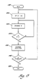
- the switch routine begins at point 452 and proceeds directly to decision step 454 at which the digital computer 126 determines whether the single input switch 94 is closed as indicated by the potential at pin 36. If the decision at decision step 454 is no, the program proceeds to decision step 456 where the digital computer 126 determines whether a switch flag has been set. If the decision at decision step 456 is no, the program proceeds immediately to an end point 458 at which the switch routine is terminated. If the decision at decision step 456 is yes, the program moves to step 460 at which a 25 millisecond delay routine is executed as shown in Figure 13. Following the delay of step 460, the switch routine proceeds to step 462 at which the switch flag is cleared, and then the program proceeds to the end point 458.
- step 454 determines if the switch flag is set. If the decision at decision step 464 is yes, the program proceeds to the end point 458. If the decision at decision step 464 is no, the program moves to step 466 at which a 25 millisecond delay routine is executed as shown in Figure 13, and then the switch routine proceeds to decision step 468.
- step 468 of the switch routine the digital computer 126 determines whether the single input switch 94 is still closed. If the decision at decision step 468 is no, the program moves directly to the end point 458. If the decision at decision step 468 is yes, the program proceeds to step 470 at which the switch flag is set. From step 470, the program moves to decision step 472 at which the digital computer 126 determines whether the heated windshield circuit is off or deenergized. If the decision at decision step 472 is no, the switch routine proceeds to step 474 at which an off routine is performed as illustrated in Figure 12. Following the off routine of step 474, the program proceeds to the end point 458.
- the switch routine proceeds to a decision step 476 at which the digital computer 126 determines whether the vehicle transmission 96 is in the park or neutral condition as indicated by the state of switch of sensor 98 at pin 34. If the decision at decision step 476 is yes, the program moves to step 478 at which a timed deice routine is executed as shown in Figure 14. Following the step 478 deice routine, the switch routine proceeds to the end point 458 at which the routine is terminated. Conversely, if the decision at decision step 476 is no, the program moves to step 480 at which a continuous defog routine is executed as shown in Figure 15. Following the defog routine of step 480, the switch routine proceeds to the end point 458 at which the routine is terminated.
- the single switch embodiment is characterized by a timed cycle and a continous cycle.
- the timed cycle is initiated in response to an initial operator closure of the single input switch 94 when the vehicle transmission 96 is in the park or neutral condition (thereby providing a deice command) and thereafter may be terminated at any time in response to a subsequent operator closure of the single input switch 94 (thereby providing an off command).
- the timed cycle includes (unless earlier terminated) a high heat deice mode of operation which is initiated when the timed cycle is initiated and which is terminated in response to the first to occur of expiration of a predetermined deice time period after initiation, or shifting of the vehicle transmission 96 to other than the park or neutral condition.
- the timed cycle further includes (unless earlier terminated) a low heat defog mode of operation which is initiated in response to termination of the deice mode of operation and which is terminated at the expiration of a predetermined defog time period after initiation.
- the continuous cycle is initiated in response to an initial operator closure of the single input switch 94 when the vehicle transmission 96 is in other than the park or neutral condition (thereby providing a defog command) and is thereafter terminated in response to a subsequent operator closure of the single input switch 94 (thereby providing an off command).
- the continuous cycle consists of the low heat defog mode of operation which is initiated when the continuous cycle is initiated and which is terminated when the continuous cycle is terminated.
Landscapes
- Engineering & Computer Science (AREA)
- Power Engineering (AREA)
- Control Of Eletrric Generators (AREA)
- Control Of Charge By Means Of Generators (AREA)
Applications Claiming Priority (4)
| Application Number | Priority Date | Filing Date | Title |
|---|---|---|---|
| US89702386A | 1986-08-15 | 1986-08-15 | |
| US897023 | 1986-08-15 | ||
| US07/050,999 US4780619A (en) | 1986-08-15 | 1987-05-15 | High DC voltage power supply for motor vehicle electrical system |
| US50999 | 1987-05-15 |
Publications (3)
| Publication Number | Publication Date |
|---|---|
| EP0256689A2 true EP0256689A2 (de) | 1988-02-24 |
| EP0256689A3 EP0256689A3 (en) | 1989-05-31 |
| EP0256689B1 EP0256689B1 (de) | 1993-01-27 |
Family
ID=26728942
Family Applications (1)
| Application Number | Title | Priority Date | Filing Date |
|---|---|---|---|
| EP19870306549 Expired - Lifetime EP0256689B1 (de) | 1986-08-15 | 1987-07-24 | Hochspannungsgleichstromversorgung für die elektrische Schaltung eines Kraftfahrzeuges |
Country Status (4)
| Country | Link |
|---|---|
| US (1) | US4780619A (de) |
| EP (1) | EP0256689B1 (de) |
| CA (1) | CA1286717C (de) |
| DE (1) | DE3783828T2 (de) |
Cited By (9)
| Publication number | Priority date | Publication date | Assignee | Title |
|---|---|---|---|---|
| WO1989006061A1 (fr) * | 1987-12-21 | 1989-06-29 | Robert Bosch Gmbh | Circuits de bord de vehicules |
| EP0325520A3 (en) * | 1988-01-20 | 1990-01-17 | Saint-Gobain Vitrage | Dual tension supply circuit for an automotive vehicle |
| EP0370468A1 (de) * | 1988-11-21 | 1990-05-30 | Hitachi, Ltd. | Stromversorgungssystem für Kraftfahrzeuge |
| EP0373805A3 (de) * | 1988-12-14 | 1991-01-09 | Texas Instruments Incorporated | Wechselstromgeneratorsystem für Kraftfahrzeuge |
| EP0407641A1 (de) * | 1989-07-13 | 1991-01-16 | Nissan Motor Co., Ltd. | Erwärmungsvorrichtung fÀ¼r Fahrzeugscheibe |
| EP0379357A3 (de) * | 1989-01-18 | 1991-08-28 | Hitachi, Ltd. | Stromversorgungsgerät für Fahrzeug |
| EP0426345A3 (en) * | 1989-11-02 | 1992-06-03 | Hitachi, Ltd. | Generator system |
| DE4225359C1 (de) * | 1992-07-31 | 1994-03-31 | Audi Ag | Drehstromgenerator mit Gleichrichter, insbesondere für ein Kraftfahrzeug |
| CN108075145A (zh) * | 2011-08-22 | 2018-05-25 | 安辛可公司 | 连到公共DC总线的ZnBr液流电池的可反转极性操作和切换方法 |
Families Citing this family (27)
| Publication number | Priority date | Publication date | Assignee | Title |
|---|---|---|---|---|
| US4947053A (en) * | 1986-08-15 | 1990-08-07 | General Motors Corporation | High DC voltage power supply for motor vehicle electrical system |
| US4878424A (en) * | 1988-11-07 | 1989-11-07 | Specialty Equipment Companies, Inc. | Cooking apparatus |
| JP2507080Y2 (ja) * | 1988-11-29 | 1996-08-14 | 日産自動車株式会社 | 車両用ウインドウの加熱装置 |
| US5187350A (en) * | 1989-06-06 | 1993-02-16 | Isuzu Motors Limited | Vehicle windshield heater utilizing regulator output current control with a voltage divider |
| US5066866A (en) * | 1989-12-26 | 1991-11-19 | Hallidy William M | Power converter system |
| DE4036363C2 (de) * | 1990-11-15 | 2001-07-19 | Bosch Gmbh Robert | Einrichtung zur thermischen Überwachung einer heizbaren Scheibe im Kraftfahrzeug |
| US5168207A (en) * | 1991-02-11 | 1992-12-01 | Ford Motor Company | Three level control system for a voltage dependent load |
| US5321231A (en) * | 1992-01-24 | 1994-06-14 | General Motors Corporation | System for supplying power to an electrically heated catalyst |
| US5350959A (en) * | 1993-05-20 | 1994-09-27 | General Motors Corporation | Electrical connector for alternating current generators |
| JP3161232B2 (ja) * | 1994-07-05 | 2001-04-25 | 国産電機株式会社 | 内燃機関用電源装置 |
| US5510696A (en) * | 1994-11-03 | 1996-04-23 | General Motors Corporation | Zero current switching between winding sets in a permanent magnet alternator having a split winding stator |
| US5808451A (en) * | 1995-12-29 | 1998-09-15 | Kokusan Denki Co., Ltd. | Power device for internal combustion engine |
| JP3839199B2 (ja) * | 1999-10-06 | 2006-11-01 | 本田技研工業株式会社 | ハイブリッド車両の制御装置 |
| JP3552614B2 (ja) * | 1999-11-11 | 2004-08-11 | トヨタ自動車株式会社 | 電源回路 |
| DE10100525A1 (de) * | 2001-01-08 | 2002-07-18 | Bosch Gmbh Robert | Verfahren zur Steuerung von Startmoment und Startleistung einer Verbrennungskraftmaschine |
| DE60231716D1 (de) * | 2001-07-09 | 2009-05-07 | Visiocorp Patents Sarl | Spiegelheizer |
| FR2842962B1 (fr) * | 2002-07-26 | 2004-12-03 | Technofan | Interface d'alimentation d'une charge depuis un reseau d'alimentation electrique |
| US7007460B2 (en) * | 2003-08-11 | 2006-03-07 | General Motors Corporation | Apparatus and method for accelerated exhaust system component heating |
| JP4049111B2 (ja) * | 2003-08-21 | 2008-02-20 | 富士電機システムズ株式会社 | 車両用ドア駆動制御装置 |
| JP4056961B2 (ja) * | 2003-10-16 | 2008-03-05 | 矢崎総業株式会社 | パワーウインドの駆動装置 |
| DE502005008245D1 (de) * | 2004-08-26 | 2009-11-12 | Abb Schweiz Ag | Vorrichtung zur speisung von hilfsbetriebeeinrichtungen für ein kraftstoffelektrisch angetriebenes fahrzeug |
| US7166943B2 (en) * | 2005-01-27 | 2007-01-23 | Hamilton Sundstrand Corporation | Rotating rectifier assembly with inner mounted diodes |
| US10221823B2 (en) * | 2006-09-13 | 2019-03-05 | John E. Traina | Method of heating and retaining heat in an internal combustion engine to improve fuel economy |
| US8080970B2 (en) * | 2009-08-07 | 2011-12-20 | Larry Seever | System and apparatus for use of a 3-phase motor in a vehicle |
| US9634596B2 (en) * | 2013-10-09 | 2017-04-25 | Michael H Gurin | Hybrid power generation with variable voltage flux |
| US20170241308A1 (en) * | 2016-02-24 | 2017-08-24 | Ford Global Technologies, Llc | Oil maintenance strategy for electrified vehicles |
| CN107336841B (zh) * | 2017-08-16 | 2023-06-16 | 威海广泰空港设备股份有限公司 | 信息化航空电源车 |
Family Cites Families (18)
| Publication number | Priority date | Publication date | Assignee | Title |
|---|---|---|---|---|
| US3258673A (en) * | 1966-06-28 | System for converting single phase | ||
| GB568430A (en) * | 1942-12-05 | 1945-04-04 | Standard Telephones Cables Ltd | Electric battery charging system |
| US3070704A (en) * | 1958-09-15 | 1962-12-25 | Gen Motors Corp | Electrical system |
| DE1194487B (de) * | 1961-03-06 | 1965-06-10 | Pintsch Bamag Ag | Stromversorgungsanlage mit einem Drehstromgenerator und nachgeschalteten Gleichrichtern |
| US3316416A (en) * | 1963-10-23 | 1967-04-25 | Gen Motors Corp | Vehicle electrical system |
| US3469072A (en) * | 1964-12-11 | 1969-09-23 | Gen Motors Corp | Electric heating system for motor vehicles |
| LU51967A1 (de) * | 1966-09-14 | 1966-11-29 | ||
| US3623139A (en) * | 1969-11-06 | 1971-11-23 | Gen Electric | Method and apparatus for automatically controlling the fast charging of rechargeable batteries |
| JPS5223308U (de) * | 1975-08-09 | 1977-02-18 | ||
| GB1483033A (en) * | 1976-02-11 | 1977-08-17 | Ford Motor Co | Vehicle window heating circuit |
| US4424477A (en) * | 1978-08-15 | 1984-01-03 | Nissan Motor Company, Ltd. | Apparatus for preventing a vehicle battery from being overdischarged |
| AU5569280A (en) * | 1979-03-02 | 1980-09-04 | Gavin Helbsy Caspersz | Electrical generating apparatus |
| US4434358A (en) * | 1980-02-13 | 1984-02-28 | Westinghouse Electric Corp. | Aircraft window heat controller with switched impedances |
| US4330818A (en) * | 1980-02-19 | 1982-05-18 | Peschel Stanley G | Variable voltage direct current power supply and motor speed control |
| DE3041201A1 (de) * | 1980-11-03 | 1982-06-09 | Robert Bosch Gmbh, 7000 Stuttgart | Verfahren und vorrichtung zur besseren ausnutzung der stromabgabe, insbesondere von drehstormgeneratoren bei kraftfahrzeugen |
| US4565919A (en) * | 1984-06-14 | 1986-01-21 | Donnelly Corporation | Crack detector for electrically conductive windshield |
| US4673797A (en) * | 1985-10-28 | 1987-06-16 | Donnelly Corporation | Power control for heated windshields |
| US4684818A (en) * | 1986-08-01 | 1987-08-04 | General Motors Corporation | Motor vehicle electrical system providing multiple DC voltages |
-
1987
- 1987-05-15 US US07/050,999 patent/US4780619A/en not_active Expired - Lifetime
- 1987-07-21 CA CA 542660 patent/CA1286717C/en not_active Expired - Lifetime
- 1987-07-24 DE DE8787306549T patent/DE3783828T2/de not_active Expired - Fee Related
- 1987-07-24 EP EP19870306549 patent/EP0256689B1/de not_active Expired - Lifetime
Cited By (10)
| Publication number | Priority date | Publication date | Assignee | Title |
|---|---|---|---|---|
| WO1989006061A1 (fr) * | 1987-12-21 | 1989-06-29 | Robert Bosch Gmbh | Circuits de bord de vehicules |
| EP0325520A3 (en) * | 1988-01-20 | 1990-01-17 | Saint-Gobain Vitrage | Dual tension supply circuit for an automotive vehicle |
| EP0370468A1 (de) * | 1988-11-21 | 1990-05-30 | Hitachi, Ltd. | Stromversorgungssystem für Kraftfahrzeuge |
| US5093583A (en) * | 1988-11-21 | 1992-03-03 | Hitachi, Ltd. | Electric power supply system for automobile |
| EP0373805A3 (de) * | 1988-12-14 | 1991-01-09 | Texas Instruments Incorporated | Wechselstromgeneratorsystem für Kraftfahrzeuge |
| EP0379357A3 (de) * | 1989-01-18 | 1991-08-28 | Hitachi, Ltd. | Stromversorgungsgerät für Fahrzeug |
| EP0407641A1 (de) * | 1989-07-13 | 1991-01-16 | Nissan Motor Co., Ltd. | Erwärmungsvorrichtung fÀ¼r Fahrzeugscheibe |
| EP0426345A3 (en) * | 1989-11-02 | 1992-06-03 | Hitachi, Ltd. | Generator system |
| DE4225359C1 (de) * | 1992-07-31 | 1994-03-31 | Audi Ag | Drehstromgenerator mit Gleichrichter, insbesondere für ein Kraftfahrzeug |
| CN108075145A (zh) * | 2011-08-22 | 2018-05-25 | 安辛可公司 | 连到公共DC总线的ZnBr液流电池的可反转极性操作和切换方法 |
Also Published As
| Publication number | Publication date |
|---|---|
| DE3783828T2 (de) | 1993-05-19 |
| CA1286717C (en) | 1991-07-23 |
| DE3783828D1 (de) | 1993-03-11 |
| EP0256689A3 (en) | 1989-05-31 |
| US4780619A (en) | 1988-10-25 |
| EP0256689B1 (de) | 1993-01-27 |
Similar Documents
| Publication | Publication Date | Title |
|---|---|---|
| EP0256689B1 (de) | Hochspannungsgleichstromversorgung für die elektrische Schaltung eines Kraftfahrzeuges | |
| US4730097A (en) | Dual mode windshield heater control | |
| US5198744A (en) | Apparatus and method for controlling the output power of a generator to maintain generator temperature below an allowed limiting value | |
| US6202615B1 (en) | Methods and apparatus for starting an internal combustion engine | |
| US4985670A (en) | Voltage regulator for AC generator with two distinct output voltage | |
| US6018199A (en) | Starter for engine equipped with motor generator | |
| US5656916A (en) | Apparatus for controlling the currents supplied for battery charging and an electric load during charging of an electric vehicle battery | |
| US6218643B1 (en) | Power supplying apparatus for automotive part | |
| US6515456B1 (en) | Battery charger apparatus | |
| US5057763A (en) | High power supply for motor vehicle | |
| KR0182305B1 (ko) | 교류 발전기의 제어 시스템 | |
| US5994787A (en) | Control system for a power supply changeover switch | |
| EP0229482A2 (de) | Feldeffekttransistor verwendender Schaltkreis und Spannungsregler | |
| US4947053A (en) | High DC voltage power supply for motor vehicle electrical system | |
| US3469072A (en) | Electric heating system for motor vehicles | |
| EP0210819B1 (de) | Regelgerät für Fahrzeuggenerator | |
| KR100268962B1 (ko) | 차량용 교류 발전기의 제어장치 | |
| US5754030A (en) | Duty ratio control for a vehicular generator responsive to low and high power loads | |
| US20020027425A1 (en) | Electrical power supply system for a vehicle | |
| EP0373805B1 (de) | Wechselstromgeneratorsystem für Kraftfahrzeuge | |
| JP3138596B2 (ja) | 車両用電源装置 | |
| EP0407633A1 (de) | Heizungssteuerungsvorrichtung für Wagenscheibe | |
| CA2044444C (en) | Control apparatus for an ac generator | |
| US5070229A (en) | Window heater controlling apparatus providing a gradual heating voltage | |
| JPS6368444A (ja) | 風防ガラス用ヒ−タを動作させるデュアルモ−ド方法 |
Legal Events
| Date | Code | Title | Description |
|---|---|---|---|
| PUAI | Public reference made under article 153(3) epc to a published international application that has entered the european phase |
Free format text: ORIGINAL CODE: 0009012 |
|
| AK | Designated contracting states |
Kind code of ref document: A2 Designated state(s): DE FR GB |
|
| PUAL | Search report despatched |
Free format text: ORIGINAL CODE: 0009013 |
|
| AK | Designated contracting states |
Kind code of ref document: A3 Designated state(s): DE FR GB |
|
| 17P | Request for examination filed |
Effective date: 19890731 |
|
| 17Q | First examination report despatched |
Effective date: 19900108 |
|
| GRAA | (expected) grant |
Free format text: ORIGINAL CODE: 0009210 |
|
| AK | Designated contracting states |
Kind code of ref document: B1 Designated state(s): DE FR GB |
|
| REF | Corresponds to: |
Ref document number: 3783828 Country of ref document: DE Date of ref document: 19930311 |
|
| ET | Fr: translation filed | ||
| PLBE | No opposition filed within time limit |
Free format text: ORIGINAL CODE: 0009261 |
|
| 26N | No opposition filed | ||
| PGFP | Annual fee paid to national office [announced via postgrant information from national office to epo] |
Ref country code: FR Payment date: 19990706 Year of fee payment: 13 |
|
| PGFP | Annual fee paid to national office [announced via postgrant information from national office to epo] |
Ref country code: GB Payment date: 19990723 Year of fee payment: 13 |
|
| PG25 | Lapsed in a contracting state [announced via postgrant information from national office to epo] |
Ref country code: GB Free format text: LAPSE BECAUSE OF NON-PAYMENT OF DUE FEES Effective date: 20000724 |
|
| PGFP | Annual fee paid to national office [announced via postgrant information from national office to epo] |
Ref country code: DE Payment date: 20000911 Year of fee payment: 14 |
|
| GBPC | Gb: european patent ceased through non-payment of renewal fee |
Effective date: 20000724 |
|
| PG25 | Lapsed in a contracting state [announced via postgrant information from national office to epo] |
Ref country code: FR Free format text: LAPSE BECAUSE OF NON-PAYMENT OF DUE FEES Effective date: 20010330 |
|
| REG | Reference to a national code |
Ref country code: FR Ref legal event code: ST |
|
| PG25 | Lapsed in a contracting state [announced via postgrant information from national office to epo] |
Ref country code: DE Free format text: LAPSE BECAUSE OF NON-PAYMENT OF DUE FEES Effective date: 20020501 |
|
| APAH | Appeal reference modified |
Free format text: ORIGINAL CODE: EPIDOSCREFNO |