EP0256715A2 - Temperaturfühlvorrichtung - Google Patents
Temperaturfühlvorrichtung Download PDFInfo
- Publication number
- EP0256715A2 EP0256715A2 EP87306757A EP87306757A EP0256715A2 EP 0256715 A2 EP0256715 A2 EP 0256715A2 EP 87306757 A EP87306757 A EP 87306757A EP 87306757 A EP87306757 A EP 87306757A EP 0256715 A2 EP0256715 A2 EP 0256715A2
- Authority
- EP
- European Patent Office
- Prior art keywords
- sensing apparatus
- temperature sensing
- temperature
- switch
- semiconductor
- Prior art date
- Legal status (The legal status is an assumption and is not a legal conclusion. Google has not performed a legal analysis and makes no representation as to the accuracy of the status listed.)
- Granted
Links
Images
Classifications
-
- G—PHYSICS
- G01—MEASURING; TESTING
- G01K—MEASURING TEMPERATURE; MEASURING QUANTITY OF HEAT; THERMALLY-SENSITIVE ELEMENTS NOT OTHERWISE PROVIDED FOR
- G01K7/00—Measuring temperature based on the use of electric or magnetic elements directly sensitive to heat ; Power supply therefor, e.g. using thermoelectric elements
- G01K7/01—Measuring temperature based on the use of electric or magnetic elements directly sensitive to heat ; Power supply therefor, e.g. using thermoelectric elements using semiconducting elements having PN junctions
-
- G—PHYSICS
- G01—MEASURING; TESTING
- G01K—MEASURING TEMPERATURE; MEASURING QUANTITY OF HEAT; THERMALLY-SENSITIVE ELEMENTS NOT OTHERWISE PROVIDED FOR
- G01K1/00—Details of thermometers not specially adapted for particular types of thermometer
- G01K1/16—Special arrangements for conducting heat from the object to the sensitive element
Definitions
- This invention relates to temperature sensing apparatus, and in particular to temperature sensing apparatus comprising at least one semiconductor device for sensing temperature.
- any MOS switch has a limit to its capability to dissipate power which, if exceeded, may result in the overheating and self-destruction of the MOS switch.
- the power dissipated by a switch is the product of the voltage across the switch and the current through the switch: the switch is normally used in conjunction with a load which, under normal operating conditions, limits the current through the switch and the voltage across it to a value within the power dissipation capability of the switch. Should the load be inadvertently short circuited, the total supply voltage will be across the switch which may result in the power dissipation capability being exceeded with the consequent overheating and destruction of the switch.
- a temperature sensing apparatus comprises a semiconductor element, at least one semiconductor device for sensing the temperature of the semiconductor element, and a means allowing both electrical isolation and thermal contact between the device and the element, the means being integral with the device and the element, and an output circuit connected to the device and arranged to provide an output indicative of the temperature of the element.
- the temperature of the element for instance an MOS switch, may be sensed and overheating readily detected.
- the semiconductor device may be integrated in polysilicon and the means providing both electrical isolation and thermal contact may comprise a dielectric layer which may be of silicon nitride and/or silicon dioxide. Consequently, the semiconductor device for sensing temperature may be positioned within a few microns of the element, thus providing a compact and rapidly reacting temperature sensor.
- the semiconductor device may consist of essentially a uni-polar junction device.
- a polysilicon diode or resistor may be utilised or, alternatively, a MOS transistor fabricated in polysilicon.
- the output means may be arranged to provide an output dependant on the current flowing through the device which may constitute an indication that the temperature of the element exceeds a predetermined threshold.
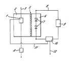
- Figure 1 depicts a schematic cross section through a MOS structure having a temperature sensing apparatus in accordance with the present invention.
- a semiconductor element 1 the temperature of which is to be sensed, is arranged in a silicon substrate 2.
- the semiconductor element 1 is a MOS switch for switching current supplied on a conductor 3 to a load 4. Heat is dissipated from the switch 1, when on, to the silicon substrate 2.
- a thin silicon oxide layer 5 bounding a portion of the silicon substrate 2 in proximity to the switch 1, allows both electrical isolation and thermal contact between the switch 1 and the semiconductor device 7 which is used for sensing the temperature of the switch 1.
- the device 7 may comprise a chain of junction devices, 7, integrated in polysilicon 6.
- the chain consists of series connected polysilicon diodes 7, of which two are illustrated.
- An output circuit, comprising a voltage source 9, is connected to apply a voltage across the chain of diodes 7 via conductor 8.
- a current detection device 10 is arranged to detect current flowing through the devices 7.
- the voltage source 9 applies a fixed voltage which is below the voltage threshold required to drive the diodes 7 into conduction, under normal operating conductions.
- the voltage threshold is, however, temperature dependant, and decreases with increasing temperature. Consequently the diodes 7 will become conducting should sufficient heat from the switch 1 be conducted to the diodes 7. In such circumstances, the current detection device 10 may provide an output signal on conductor 11 to turn off MOS switch 1.
- the precise form of the semiconductor devices 7, the voltage applied by source 9, the proximity of the devices 7 to the switch 1 and the thermal conductivity of the interspaced portion between switch 1 and device 7 are at least some of the factors to be taken into account in arranging for the output circuit to provide a predetermined output indicative of the temperature of the switch 1, and, in particular, of the overheating of the switch 1 above a predetermined level.
- the temperature sensing apparatus may be arranged so that the current detection circuit 10 provides an output 12 indicative of the actual temperature of the switch 1, in dependence, for instance upon the amount of current flowing or the voltage applied by voltage source 9.
- semiconductor devices 7 may be utilised which are arranged to allow current flow in an output circuit only when the devices are below a predetermined temperature.
Landscapes
- Physics & Mathematics (AREA)
- General Physics & Mathematics (AREA)
- Semiconductor Integrated Circuits (AREA)
- Measuring Temperature Or Quantity Of Heat (AREA)
Applications Claiming Priority (4)
| Application Number | Priority Date | Filing Date | Title |
|---|---|---|---|
| GB8620031 | 1986-08-18 | ||
| GB868620031A GB8620031D0 (en) | 1986-08-18 | 1986-08-18 | Protection of mos structures against overheating |
| GB8714380 | 1987-06-19 | ||
| GB8714380A GB2195507B (en) | 1986-08-18 | 1987-06-19 | Temperature sensing apparatus |
Publications (3)
| Publication Number | Publication Date |
|---|---|
| EP0256715A2 true EP0256715A2 (de) | 1988-02-24 |
| EP0256715A3 EP0256715A3 (en) | 1989-08-09 |
| EP0256715B1 EP0256715B1 (de) | 1992-02-26 |
Family
ID=26291186
Family Applications (1)
| Application Number | Title | Priority Date | Filing Date |
|---|---|---|---|
| EP87306757A Expired - Lifetime EP0256715B1 (de) | 1986-08-18 | 1987-07-30 | Temperaturfühlvorrichtung |
Country Status (4)
| Country | Link |
|---|---|
| US (1) | US4854731A (de) |
| EP (1) | EP0256715B1 (de) |
| JP (1) | JP2677798B2 (de) |
| DE (1) | DE3776836D1 (de) |
Cited By (3)
| Publication number | Priority date | Publication date | Assignee | Title |
|---|---|---|---|---|
| RU2206878C1 (ru) * | 2001-10-01 | 2003-06-20 | ОАО Казанский вертолетный завод | Способ измерения пространственного распределения температуры и устройство для его осуществления |
| EP1564404A1 (de) * | 2004-02-17 | 2005-08-17 | Delphi Technologies, Inc. | Zündsystem für Kraftfahrzeuge mit funkloser sanfter Abschaltung als Thermisch-Überbelastungschutz |
| US8155916B2 (en) | 2008-07-07 | 2012-04-10 | Infineon Technologies Ag | Semiconductor component and method of determining temperature |
Families Citing this family (19)
| Publication number | Priority date | Publication date | Assignee | Title |
|---|---|---|---|---|
| JPS63253223A (ja) * | 1987-04-09 | 1988-10-20 | Terumo Corp | 温度測定器 |
| US5070322A (en) * | 1989-07-19 | 1991-12-03 | Fuji Electric Co., Ltd. | An overheating detection circuit including a reversely biased junction having a temperature dependent reverse leakage current for detecting overheating of a power integrated circuit |
| US5025298A (en) * | 1989-08-22 | 1991-06-18 | Motorola, Inc. | Semiconductor structure with closely coupled substrate temperature sense element |
| US5008736A (en) * | 1989-11-20 | 1991-04-16 | Motorola, Inc. | Thermal protection method for a power device |
| US5355123A (en) * | 1990-07-17 | 1994-10-11 | Fuji Electric Co., Ltd. | Overheating detection circuit for detecting overheating of a power device |
| US5349336A (en) * | 1990-07-17 | 1994-09-20 | Fuji Electric Co., Ltd. | Overheating detection circuit for detecting overheating of a power device |
| US5302024A (en) * | 1990-10-09 | 1994-04-12 | Lockheed Sanders, Inc. | Monolithic microwave power sensor using a heat sensing diode junction |
| US5221142A (en) * | 1991-05-20 | 1993-06-22 | Peak Systems, Inc. | Method and apparatus for temperature measurement using thermal expansion |
| US5154514A (en) * | 1991-08-29 | 1992-10-13 | International Business Machines Corporation | On-chip temperature sensor utilizing a Schottky barrier diode structure |
| US5230564A (en) * | 1992-03-20 | 1993-07-27 | Cray Research, Inc. | Temperature monitoring system for air-cooled electric components |
| US5664118A (en) * | 1994-03-28 | 1997-09-02 | Kabushiki Kaisha Toshiba | Computer system having detachable expansion unit |
| US5930110A (en) * | 1994-03-28 | 1999-07-27 | Kabushiki Kaisha Toshiba | Computer system having detachable expansion unit |
| US6463396B1 (en) * | 1994-05-31 | 2002-10-08 | Kabushiki Kaisha Toshiba | Apparatus for controlling internal heat generating circuit |
| US5781075A (en) * | 1996-11-01 | 1998-07-14 | Motorola, Inc. | Temperature sensing apparatus |
| US6453218B1 (en) | 1999-03-29 | 2002-09-17 | Intel Corporation | Integrated RAM thermal sensor |
| DE10133736A1 (de) * | 2001-07-11 | 2003-01-23 | Philips Corp Intellectual Pty | Anordnung zum Messen der Temperatur einer elektronischen Schaltung |
| JP3928566B2 (ja) * | 2003-01-30 | 2007-06-13 | 株式会社デンソー | 過熱検出装置および半導体集積回路装置 |
| US8582266B2 (en) * | 2006-02-17 | 2013-11-12 | Broadcom Corporation | Current-monitoring apparatus |
| US8432214B2 (en) | 2011-03-21 | 2013-04-30 | Freescale Semiconductor, Inc. | Programmable temperature sensing circuit for an integrated circuit |
Family Cites Families (14)
| Publication number | Priority date | Publication date | Assignee | Title |
|---|---|---|---|---|
| US3182201A (en) * | 1960-12-01 | 1965-05-04 | Sklar Bernard | Apparatus for detecting localized high temperatures in electronic components |
| GB1008473A (en) * | 1963-05-30 | 1965-10-27 | English Electric Co Ltd | Improvements in or relating to temperature measurement |
| US3440883A (en) * | 1966-12-01 | 1969-04-29 | Monsanto Co | Electronic semiconductor thermometer |
| US3566690A (en) * | 1969-08-20 | 1971-03-02 | Northern Electric Co | Thermal delay semiconductor thermometer |
| US3934476A (en) * | 1969-09-11 | 1976-01-27 | Lamb Ii Harry H | Linear telethermometer |
| US4003038A (en) * | 1975-06-09 | 1977-01-11 | Multi-State Devices Ltd. | Thermal discriminator for sensing variations in the heat exchange properties of a medium |
| JPS54107688A (en) * | 1978-02-13 | 1979-08-23 | Seiko Epson Corp | Semiconductor integrated circuit for temperature detection |
| DE2933874C2 (de) * | 1978-08-24 | 1986-07-17 | Hochiki Corp., Tokio/Tokyo | Fühlvorrichtung zur Wahrnehmung von Temperaturunterschieden zwischen zwei Punkten |
| US4184126A (en) * | 1978-09-27 | 1980-01-15 | Eaton Corporation | Temperature sensitive astable multivibrator |
| JPS56120153A (en) * | 1980-02-28 | 1981-09-21 | Seiko Epson Corp | Temperature protector for integrated circuit |
| JPS59107226A (ja) * | 1982-12-10 | 1984-06-21 | Citizen Watch Co Ltd | 温度検出器 |
| JPS60241247A (ja) * | 1984-05-16 | 1985-11-30 | Nec Corp | 半導体装置 |
| DE3431811A1 (de) * | 1984-08-30 | 1986-03-13 | Philips Patentverwaltung Gmbh, 2000 Hamburg | Halbleiter-temperatursensor |
| JPS61189657A (ja) * | 1985-02-18 | 1986-08-23 | Fuji Photo Film Co Ltd | 半導体素子温度制御装置 |
-
1987
- 1987-07-30 EP EP87306757A patent/EP0256715B1/de not_active Expired - Lifetime
- 1987-07-30 DE DE8787306757T patent/DE3776836D1/de not_active Expired - Lifetime
- 1987-08-03 US US07/080,890 patent/US4854731A/en not_active Expired - Fee Related
- 1987-08-17 JP JP62203227A patent/JP2677798B2/ja not_active Expired - Lifetime
Cited By (5)
| Publication number | Priority date | Publication date | Assignee | Title |
|---|---|---|---|---|
| RU2206878C1 (ru) * | 2001-10-01 | 2003-06-20 | ОАО Казанский вертолетный завод | Способ измерения пространственного распределения температуры и устройство для его осуществления |
| EP1564404A1 (de) * | 2004-02-17 | 2005-08-17 | Delphi Technologies, Inc. | Zündsystem für Kraftfahrzeuge mit funkloser sanfter Abschaltung als Thermisch-Überbelastungschutz |
| US6955164B2 (en) | 2004-02-17 | 2005-10-18 | Delphi Technologies, Inc. | Automotive ignition system with sparkless thermal overload protection |
| US8155916B2 (en) | 2008-07-07 | 2012-04-10 | Infineon Technologies Ag | Semiconductor component and method of determining temperature |
| US8478559B2 (en) | 2008-07-07 | 2013-07-02 | Infineon Technologies Ag | Semiconductor component and method of making the same |
Also Published As
| Publication number | Publication date |
|---|---|
| EP0256715A3 (en) | 1989-08-09 |
| DE3776836D1 (de) | 1992-04-02 |
| EP0256715B1 (de) | 1992-02-26 |
| US4854731A (en) | 1989-08-08 |
| JP2677798B2 (ja) | 1997-11-17 |
| JPS6350053A (ja) | 1988-03-02 |
Similar Documents
| Publication | Publication Date | Title |
|---|---|---|
| EP0256715B1 (de) | Temperaturfühlvorrichtung | |
| US4896199A (en) | Semiconductor device with protective means against overheating | |
| US6504697B1 (en) | Arrangement and method for measuring a temperature | |
| US5289043A (en) | Switching system for selectively enabling electrical power to be applied to plural loads | |
| JP2731119B2 (ja) | 半導体パワー素子およびその遮断回路 | |
| US4685081A (en) | Peltier junction used for thermal control of solid state devices | |
| KR0145069B1 (ko) | 기판온도 감지소자를 구비한 반도체 구조물 및 그 형성공정 | |
| JPS625345B2 (de) | ||
| KR100599214B1 (ko) | 보호기능을 구비한 반도체 장치 | |
| WO2006097896A1 (en) | Mosfet with temperature sense facility | |
| US5969927A (en) | Integrated overload protective device | |
| JP2677735B2 (ja) | 混成集積回路装置 | |
| JP2522208B2 (ja) | 半導体装置 | |
| JPH0795657B2 (ja) | 保護機能内蔵型mosfet | |
| GB2195507A (en) | Temperature sensing apparatus | |
| JPH0834222B2 (ja) | 半導体装置 | |
| EP0480517B1 (de) | Eine temperaturgesteuerte Schaltung | |
| JPH0832361A (ja) | 保護装置付き増幅回路 | |
| JPH05129598A (ja) | パワーデバイスの過熱検出回路 | |
| EP0565807A1 (de) | MOS-Leistungstransistorbauelement | |
| JP2681990B2 (ja) | 保護機能を備えた半導体装置 | |
| US5396120A (en) | Semiconductor integrated unit | |
| JP3042256B2 (ja) | パワートランジスタ温度保護回路装置 | |
| JP2001028437A (ja) | 過電流保護装置 | |
| US5534726A (en) | Semiconductor device provided with status detecting function |
Legal Events
| Date | Code | Title | Description |
|---|---|---|---|
| PUAI | Public reference made under article 153(3) epc to a published international application that has entered the european phase |
Free format text: ORIGINAL CODE: 0009012 |
|
| AK | Designated contracting states |
Kind code of ref document: A2 Designated state(s): BE DE FR GB IT NL |
|
| PUAL | Search report despatched |
Free format text: ORIGINAL CODE: 0009013 |
|
| AK | Designated contracting states |
Kind code of ref document: A3 Designated state(s): BE DE FR GB IT NL |
|
| 17P | Request for examination filed |
Effective date: 19890826 |
|
| 17Q | First examination report despatched |
Effective date: 19901025 |
|
| RBV | Designated contracting states (corrected) |
Designated state(s): BE DE FR IT NL |
|
| GRAA | (expected) grant |
Free format text: ORIGINAL CODE: 0009210 |
|
| AK | Designated contracting states |
Kind code of ref document: B1 Designated state(s): BE DE FR IT NL |
|
| REF | Corresponds to: |
Ref document number: 3776836 Country of ref document: DE Date of ref document: 19920402 |
|
| ET | Fr: translation filed | ||
| ITF | It: translation for a ep patent filed | ||
| PLBE | No opposition filed within time limit |
Free format text: ORIGINAL CODE: 0009261 |
|
| STAA | Information on the status of an ep patent application or granted ep patent |
Free format text: STATUS: NO OPPOSITION FILED WITHIN TIME LIMIT |
|
| 26N | No opposition filed | ||
| ITTA | It: last paid annual fee | ||
| PGFP | Annual fee paid to national office [announced via postgrant information from national office to epo] |
Ref country code: BE Payment date: 20020205 Year of fee payment: 15 |
|
| PG25 | Lapsed in a contracting state [announced via postgrant information from national office to epo] |
Ref country code: BE Free format text: LAPSE BECAUSE OF NON-PAYMENT OF DUE FEES Effective date: 20020731 |
|
| BERE | Be: lapsed |
Owner name: *SILICONIX LTD Effective date: 20020731 |
|
| PGFP | Annual fee paid to national office [announced via postgrant information from national office to epo] |
Ref country code: FR Payment date: 20030718 Year of fee payment: 17 |
|
| PGFP | Annual fee paid to national office [announced via postgrant information from national office to epo] |
Ref country code: NL Payment date: 20030721 Year of fee payment: 17 |
|
| PG25 | Lapsed in a contracting state [announced via postgrant information from national office to epo] |
Ref country code: NL Free format text: LAPSE BECAUSE OF NON-PAYMENT OF DUE FEES Effective date: 20050201 |
|
| PG25 | Lapsed in a contracting state [announced via postgrant information from national office to epo] |
Ref country code: FR Free format text: LAPSE BECAUSE OF NON-PAYMENT OF DUE FEES Effective date: 20050331 |
|
| NLV4 | Nl: lapsed or anulled due to non-payment of the annual fee |
Effective date: 20050201 |
|
| REG | Reference to a national code |
Ref country code: FR Ref legal event code: ST |
|
| PG25 | Lapsed in a contracting state [announced via postgrant information from national office to epo] |
Ref country code: IT Free format text: LAPSE BECAUSE OF NON-PAYMENT OF DUE FEES;WARNING: LAPSES OF ITALIAN PATENTS WITH EFFECTIVE DATE BEFORE 2007 MAY HAVE OCCURRED AT ANY TIME BEFORE 2007. THE CORRECT EFFECTIVE DATE MAY BE DIFFERENT FROM THE ONE RECORDED. Effective date: 20050730 |
|
| PGFP | Annual fee paid to national office [announced via postgrant information from national office to epo] |
Ref country code: DE Payment date: 20061002 Year of fee payment: 20 |