EP0256913A1 - Wärmetauscher mit Rohrkanälen und Endkammern aus Kunststoff - Google Patents
Wärmetauscher mit Rohrkanälen und Endkammern aus Kunststoff Download PDFInfo
- Publication number
- EP0256913A1 EP0256913A1 EP87401736A EP87401736A EP0256913A1 EP 0256913 A1 EP0256913 A1 EP 0256913A1 EP 87401736 A EP87401736 A EP 87401736A EP 87401736 A EP87401736 A EP 87401736A EP 0256913 A1 EP0256913 A1 EP 0256913A1
- Authority
- EP
- European Patent Office
- Prior art keywords
- fluid box
- heat exchanger
- tubes
- fluid
- ribs
- Prior art date
- Legal status (The legal status is an assumption and is not a legal conclusion. Google has not performed a legal analysis and makes no representation as to the accuracy of the status listed.)
- Granted
Links
- 229920003023 plastic Polymers 0.000 title claims abstract description 8
- 239000004033 plastic Substances 0.000 title claims abstract description 8
- 239000012530 fluid Substances 0.000 claims abstract description 62
- 230000000149 penetrating effect Effects 0.000 claims abstract 2
- 238000003466 welding Methods 0.000 claims description 3
- 238000000465 moulding Methods 0.000 abstract description 3
- 239000000463 material Substances 0.000 abstract description 2
- XLYOFNOQVPJJNP-UHFFFAOYSA-N water Substances O XLYOFNOQVPJJNP-UHFFFAOYSA-N 0.000 description 2
- 230000004308 accommodation Effects 0.000 description 1
- 210000000078 claw Anatomy 0.000 description 1
- 238000001816 cooling Methods 0.000 description 1
- 230000007423 decrease Effects 0.000 description 1
- 230000002093 peripheral effect Effects 0.000 description 1
Images

Classifications
-
- F—MECHANICAL ENGINEERING; LIGHTING; HEATING; WEAPONS; BLASTING
- F28—HEAT EXCHANGE IN GENERAL
- F28F—DETAILS OF HEAT-EXCHANGE AND HEAT-TRANSFER APPARATUS, OF GENERAL APPLICATION
- F28F21/00—Constructions of heat-exchange apparatus characterised by the selection of particular materials
- F28F21/06—Constructions of heat-exchange apparatus characterised by the selection of particular materials of plastics material
- F28F21/067—Details
-
- F—MECHANICAL ENGINEERING; LIGHTING; HEATING; WEAPONS; BLASTING
- F28—HEAT EXCHANGE IN GENERAL
- F28F—DETAILS OF HEAT-EXCHANGE AND HEAT-TRANSFER APPARATUS, OF GENERAL APPLICATION
- F28F9/00—Casings; Header boxes; Auxiliary supports for elements; Auxiliary members within casings
- F28F9/001—Casings in the form of plate-like arrangements; Frames enclosing a heat exchange core
-
- F—MECHANICAL ENGINEERING; LIGHTING; HEATING; WEAPONS; BLASTING
- F28—HEAT EXCHANGE IN GENERAL
- F28F—DETAILS OF HEAT-EXCHANGE AND HEAT-TRANSFER APPARATUS, OF GENERAL APPLICATION
- F28F9/00—Casings; Header boxes; Auxiliary supports for elements; Auxiliary members within casings
- F28F9/02—Header boxes; End plates
-
- F—MECHANICAL ENGINEERING; LIGHTING; HEATING; WEAPONS; BLASTING
- F28—HEAT EXCHANGE IN GENERAL
- F28F—DETAILS OF HEAT-EXCHANGE AND HEAT-TRANSFER APPARATUS, OF GENERAL APPLICATION
- F28F9/00—Casings; Header boxes; Auxiliary supports for elements; Auxiliary members within casings
- F28F9/02—Header boxes; End plates
- F28F9/0219—Arrangements for sealing end plates into casing or header box; Header box sub-elements
- F28F9/0221—Header boxes or end plates formed by stacked elements
-
- F—MECHANICAL ENGINEERING; LIGHTING; HEATING; WEAPONS; BLASTING
- F28—HEAT EXCHANGE IN GENERAL
- F28F—DETAILS OF HEAT-EXCHANGE AND HEAT-TRANSFER APPARATUS, OF GENERAL APPLICATION
- F28F2225/00—Reinforcing means
- F28F2225/08—Reinforcing means for header boxes
Definitions
- the invention relates to a heat exchanger with a tube bundle and plastic fluid boxes, in particular a radiator for the cooling of a truck engine.
- heat exchangers of the type comprising a bundle of parallel tubes and, at at least one end thereof, a plastic fluid box, the ends of the tubes entering the fluid box in a liquid-tight manner by holes made in a wall of the fluid box forming a manifold, and further comprising at least one mounting cross member extending parallel to the tubes and fixed respectively to one end of the fluid box, in an offset region, in the direction longitudinal of the tubes and towards the median transverse plane thereof, relative to the manifold.
- the fluid box has a flange on which are fixed, on the one hand, the manifold and on the other hand, intermediate parts used for mounting the cross member, the fixing of said intermediate parts made by claws or legs folded over the edge of the water box.
- the assembly of the heat exchanger is complicated since it is necessary to fix the intermediate parts between each fluid box and each crosspiece.
- the fluid boxes must be of a very specific type in which the collector is an independent piece which has just been attached and fixed on the peripheral edge of the fluid box.
- the bottoms which form the ends of the fluid boxes extend perpendicular to the longitudinal direction of the fluid box, that is to say parallel to the longitudinal direction of the tubes. . It follows that the size of the heat exchanger in the plane defined by the longitudinal direction of the tubes and the longitudinal direction of the fluid boxes is substantially that of a rectangle. Consequently, the width of the heat exchanger, i.e. its dimension in the longitudinal direction of the fluid boxes, remains constant over its entire height, i.e. over its extent in the direction longitudinal of the tubes.
- the object of the invention is to provide a heat exchanger allowing particularly simple mounting of the cross member (s) on each fluid box, regardless of the type of fluid box used.
- Another object of the invention is to provide a heat exchanger structure allowing a reduction in local width.
- the assembly of the heat exchanger is much simpler.
- the rigidity of the heat exchanger is increased due to the fact that the bases and the ribs are integral with the fluid box.
- the base extends parallel to the tubes and is connected to the fluid box by two parallel ribs.
- these ribs have the shape of a right triangle.
- the invention applies to any type of plastic fluid box, in particular to those comprising a tubular wall including a manifold-shaped portion.
- a tubular wall including a manifold-shaped portion.
- one end of the tubular wall, which forms the bottom is molded, while the other end is open to receive a bottom cover.
- the invention also applies to fluid boxes in which the two end bottoms have come from molding and in which the collector consists of another piece of plastic material which is attached and fixed, for example by welding, to the rest of the fluid box.
- the invention can also be applied to fluid boxes in a single section or in two sections.
- each fluid box consist of funds extending obliquely so that the length of the fluid box is less in its longitudinal zone opposite to the collector than in the longitudinal zone of the collector, which makes it possible to locally reduce the overall dimensions in width of the heat exchanger.
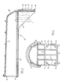
- the radiator shown in Figure 1 has, seen from the front according to Figure 1, the general shape of a rectangle whose sides extend vertically and horizontally. It essentially comprises a bundle of parallel tubes 1 directed vertically and regularly distributed in several rows over the width of the radiator. To simplify the drawing, only two tubes 1 are shown in Figure 1 in the vicinity of one of the vertical edges of the radiator. The ends of the tubes 1 open into fluid boxes, for example water boxes, of generally tubular shape 2-1, 2-2, extending respectively along the upper and lower horizontal sides of the radiator.
- Each of the fluid boxes is, in the example, formed of two tubular sections 20 molded from plastic and assembled together by welding.
- Each tubular section 20 which is molded in one piece has, as shown in Figures 2 and 3, a tubular wall 21, a bottom 22 closing one end of the wall 21, an assembly base 23 extending parallel to the tubes 1 and two ribs 24 connecting the base 23 to the tubular wall 21.
- These two ribs are parallel and have the shape general of a right triangle (figure 2).
- the end 25, opposite the bottom 22, of the tubular wall is open.
- Two sections 20 are welded to each other by friction through their end faces 26 surrounding the opening 25, thus producing a tubular fluid box closed at its two ends by the oblique bottoms 22.
- the tubular wall 21 of each fluid box comprises a flat wall portion 27 forming a manifold, crossed in a liquid-tight manner by the ends of the tubes 1 in a manner known per se.
- the oblique bottoms 22 are oriented so that the length of the fluid box, that is to say the width of the radiator, decreases from the plane of the collector towards the part opposite the latter of the tubular wall. 21, that is to say towards the upper or lower end of the radiator. The angles of these are therefore chamfered, which facilitates its accommodation in the vehicle body.
- the bases 23 of the tubular sections 20 serving to assemble them to profiled crosspieces 3 extending along the vertical sides of the radiator.
- Each cross member 3 comprises a back 30 forming the corresponding lateral face of the radiator and two wings 31 extending along the main faces thereof.
- the crosspieces 3 serve to reinforce the structure of the radiator and to mount it on the vehicle by means of lugs 41 and 42 which are fixed to it.
- the internal face of the backs 30 rests on horizontal ribs 50 and vertical ribs 51 belonging to the base 23 and defining, by their vertices, a support plane 52 for the crosspieces (FIGS. 2 and 3).
- the support plane 52 is perpendicular to the longitudinal direction fluid boxes, therefore parallel to the longitudinal direction of the tubes 1.
- Each base 23 is crossed by four holes 53 surrounded by bosses 54 which terminate in the support plane 52.
- These holes 53 and corresponding holes made in the back crosspieces allow the assembly of the latter to the fluid boxes by assembly elements 6 such as rivets or screws for example.
- each base 23 is offset, relative to the tubular wall 21, in the direction of the median transverse plane M of the tubes 1 ( Figure 1). More specifically, the base is on the side of the plane M with respect to the plane of the manifold 27. Ribs 24 extending substantially along the two main faces of the radiator respectively ensure a rigid connection of the base to the tubular wall 21. Each rib 24 has the shape of a right triangle of which one side of the right angle coincides with a vertical side of the base and the other of which corresponds to a part of the longitudinal side of the manifold. The hypotenuse of the right triangle forms a free side of the rib.
- the fluid boxes 2-1 and 2-2 are linked to each other in their central region by two tie rods 55 passing through holes made in bosses 56 provided on the tubular walls of the tubular sections 20.
- These tie rods 55 support the longitudinal forces due to the tendency of the fluid boxes to bend when the radiator is full of pressurized fluid, and thus prevent tearing forces being exerted on the welds of the ends of the tubular sections.
- One of the ends 57 of each tie rod is folded at a right angle and rests on a boss 56, while the opposite end 58 is threaded and cooperates with a nut 59 which is tightened on another boss 56.
- heat exchangers comprising one or two crosspieces.
Landscapes
- Engineering & Computer Science (AREA)
- Physics & Mathematics (AREA)
- Thermal Sciences (AREA)
- Mechanical Engineering (AREA)
- General Engineering & Computer Science (AREA)
- Heat-Exchange Devices With Radiators And Conduit Assemblies (AREA)
Applications Claiming Priority (2)
| Application Number | Priority Date | Filing Date | Title |
|---|---|---|---|
| FR8611471 | 1986-08-07 | ||
| FR8611471A FR2602581B1 (fr) | 1986-08-07 | 1986-08-07 | Echangeur de chaleur a faisceau de tubes et boites a fluide en matiere plastique |
Publications (3)
| Publication Number | Publication Date |
|---|---|
| EP0256913A1 true EP0256913A1 (de) | 1988-02-24 |
| EP0256913B1 EP0256913B1 (de) | 1990-04-04 |
| EP0256913B2 EP0256913B2 (de) | 1994-06-15 |
Family
ID=9338131
Family Applications (1)
| Application Number | Title | Priority Date | Filing Date |
|---|---|---|---|
| EP19870401736 Expired - Lifetime EP0256913B2 (de) | 1986-08-07 | 1987-07-24 | Wärmetauscher mit Rohrkanälen und Endkammern aus Kunststoff |
Country Status (4)
| Country | Link |
|---|---|
| EP (1) | EP0256913B2 (de) |
| DE (1) | DE3762163D1 (de) |
| ES (1) | ES2013769T5 (de) |
| FR (1) | FR2602581B1 (de) |
Cited By (7)
| Publication number | Priority date | Publication date | Assignee | Title |
|---|---|---|---|---|
| EP0504034A1 (de) * | 1991-03-12 | 1992-09-16 | Valeo Thermique Moteur | Wärmetauscher mit verbundenen Wasserkästen für Fahrzeuge |
| EP0567411A1 (de) * | 1992-04-24 | 1993-10-27 | Valeo Thermique Moteur | Seitenteil für die Montage eines Fahrzeugradiators |
| US5257662A (en) * | 1992-03-27 | 1993-11-02 | The Allen Group Inc. | Heat exchanger assembly |
| JP2000283689A (ja) * | 1999-03-30 | 2000-10-13 | Denso Corp | 熱交換器 |
| ES2153721A1 (es) * | 1997-08-07 | 2001-03-01 | Frape Behr Sa | Estructura para adaptacion de un radiador a un a cavidad alojadora |
| US7198097B2 (en) * | 2003-12-18 | 2007-04-03 | Valeo, Inc. | Angled ribs for heat exchanger tanks |
| CN108759543A (zh) * | 2018-06-14 | 2018-11-06 | 黄山科能汽车散热器有限公司 | 一种车辆散热器 |
Families Citing this family (2)
| Publication number | Priority date | Publication date | Assignee | Title |
|---|---|---|---|---|
| WO2000022366A1 (en) | 1998-10-09 | 2000-04-20 | S.C. Romradiatoare S.A. | High efficiency heat exchanger with oval tubes |
| CN104567513A (zh) * | 2014-12-26 | 2015-04-29 | 无锡博利达换热器有限公司 | 水冷却器 |
Citations (6)
| Publication number | Priority date | Publication date | Assignee | Title |
|---|---|---|---|---|
| FR2472734A1 (fr) * | 1979-12-29 | 1981-07-03 | Sueddeutsche Kuehler Behr | Perfectionnements apportes aux echangeurs de chaleur notamment pour radiateurs de vehicules automobiles |
| GB2078361A (en) * | 1980-06-24 | 1982-01-06 | Delanair Ltd | Heat exchangers and heat exchanger headers |
| GB2090958A (en) * | 1980-11-24 | 1982-07-21 | Chausson Usines Sa | Heat exchangers |
| EP0115795A1 (de) * | 1983-02-05 | 1984-08-15 | Behr GmbH & Co. | Wasser/Luft-Kühler für wassergekühlte Verbrennungskraftmaschinen, insbesondere von Nutzfahrzeugen |
| EP0170952A1 (de) * | 1984-08-04 | 1986-02-12 | Behr GmbH & Co. | Wasser/Luft-Kühler für wassergekühlte Verbrennungskraftmaschinen |
| DE8629407U1 (de) * | 1985-11-04 | 1987-01-22 | Süddeutsche Kühlerfabrik Julius Fr. Behr GmbH & Co KG, 7000 Stuttgart | Kühler für Kraftfahrzeuge |
-
1986
- 1986-08-07 FR FR8611471A patent/FR2602581B1/fr not_active Expired
-
1987
- 1987-07-24 EP EP19870401736 patent/EP0256913B2/de not_active Expired - Lifetime
- 1987-07-24 ES ES87401736T patent/ES2013769T5/es not_active Expired - Lifetime
- 1987-07-24 DE DE8787401736T patent/DE3762163D1/de not_active Expired - Lifetime
Patent Citations (6)
| Publication number | Priority date | Publication date | Assignee | Title |
|---|---|---|---|---|
| FR2472734A1 (fr) * | 1979-12-29 | 1981-07-03 | Sueddeutsche Kuehler Behr | Perfectionnements apportes aux echangeurs de chaleur notamment pour radiateurs de vehicules automobiles |
| GB2078361A (en) * | 1980-06-24 | 1982-01-06 | Delanair Ltd | Heat exchangers and heat exchanger headers |
| GB2090958A (en) * | 1980-11-24 | 1982-07-21 | Chausson Usines Sa | Heat exchangers |
| EP0115795A1 (de) * | 1983-02-05 | 1984-08-15 | Behr GmbH & Co. | Wasser/Luft-Kühler für wassergekühlte Verbrennungskraftmaschinen, insbesondere von Nutzfahrzeugen |
| EP0170952A1 (de) * | 1984-08-04 | 1986-02-12 | Behr GmbH & Co. | Wasser/Luft-Kühler für wassergekühlte Verbrennungskraftmaschinen |
| DE8629407U1 (de) * | 1985-11-04 | 1987-01-22 | Süddeutsche Kühlerfabrik Julius Fr. Behr GmbH & Co KG, 7000 Stuttgart | Kühler für Kraftfahrzeuge |
Cited By (10)
| Publication number | Priority date | Publication date | Assignee | Title |
|---|---|---|---|---|
| EP0504034A1 (de) * | 1991-03-12 | 1992-09-16 | Valeo Thermique Moteur | Wärmetauscher mit verbundenen Wasserkästen für Fahrzeuge |
| FR2674014A1 (fr) * | 1991-03-12 | 1992-09-18 | Valeo Thermique Moteur Sa | Echangeur de chaleur a boites a eau reliees pour vehicules automobiles. |
| US5257662A (en) * | 1992-03-27 | 1993-11-02 | The Allen Group Inc. | Heat exchanger assembly |
| US5373896A (en) * | 1992-03-27 | 1994-12-20 | The Allen Group | Heat exchanger assembly |
| EP0567411A1 (de) * | 1992-04-24 | 1993-10-27 | Valeo Thermique Moteur | Seitenteil für die Montage eines Fahrzeugradiators |
| FR2690514A1 (fr) * | 1992-04-24 | 1993-10-29 | Valeo Thermique Moteur Sa | Traverse pour le montage d'un radiateur de véhicule. |
| ES2153721A1 (es) * | 1997-08-07 | 2001-03-01 | Frape Behr Sa | Estructura para adaptacion de un radiador a un a cavidad alojadora |
| JP2000283689A (ja) * | 1999-03-30 | 2000-10-13 | Denso Corp | 熱交換器 |
| US7198097B2 (en) * | 2003-12-18 | 2007-04-03 | Valeo, Inc. | Angled ribs for heat exchanger tanks |
| CN108759543A (zh) * | 2018-06-14 | 2018-11-06 | 黄山科能汽车散热器有限公司 | 一种车辆散热器 |
Also Published As
| Publication number | Publication date |
|---|---|
| EP0256913B2 (de) | 1994-06-15 |
| DE3762163D1 (de) | 1990-05-10 |
| ES2013769T5 (es) | 1995-08-16 |
| ES2013769B3 (es) | 1990-06-01 |
| EP0256913B1 (de) | 1990-04-04 |
| FR2602581B1 (fr) | 1989-07-21 |
| FR2602581A1 (fr) | 1988-02-12 |
Similar Documents
| Publication | Publication Date | Title |
|---|---|---|
| FR2761331A1 (fr) | Structure de module d'extremite avant d'un vehicule | |
| EP0256913B1 (de) | Wärmetauscher mit Rohrkanälen und Endkammern aus Kunststoff | |
| FR2544480A1 (fr) | Radiateurs avec des reservoirs superieur et inferieur qui comportent des collecteurs superieur et inferieur respectifs | |
| EP0501855A1 (de) | Rohrschlangenwärmetauscher | |
| CA1286975C (fr) | Support de siege pour vehicule de transport en commun et siege equipe de ce support | |
| FR2735557A1 (fr) | Raccord pour profiles | |
| EP0903452B1 (de) | Verbesserte Verbindungseinrichtung von Pfosten und Paneelen | |
| EP0647824B1 (de) | Wärmetauscher, insbesondere als Ölkühler benutzt | |
| FR2769569A1 (fr) | Dispositif de fixation d'une facade avant a la structure avant d'un vehicule automobile | |
| FR2602580A1 (fr) | Echangeur de chaleur a faisceau de tubes et boites a fluide tubulaires | |
| FR2772904A1 (fr) | Dispositif pour l'assemblage de deux equipements sur un echangeur de chaleur, en particulier de vehicule automobile | |
| FR2800862A1 (fr) | Radiateur de fluide de refroidissement comportant un reservoir de compensation | |
| EP0950551B1 (de) | Tiefliegendes Querelement zum Verbinden eines Zugfahrzeuges mit einem Anhänger | |
| EP0014155A1 (de) | Gerüstbrett und Vorrichtung zur Montage dieses Brettes auf einem Gerüst | |
| FR2814537A1 (fr) | Echangeur de chaleur pour deux fluides a rendement ameliore | |
| EP0780655A1 (de) | Wärmetauscher mit gelötetem Wasserkasten, insbesondere für ein Kraftfahrzeug | |
| EP1957927B1 (de) | Verstärkter sammler für den sammelbehälter eines wärmetauschers und einen solchen sammler umfassender sammelbehälter | |
| FR2819162A1 (fr) | Dispositif de suspension de lattes de sommier | |
| EP0908117A1 (de) | Metallschrankbausatz | |
| FR2697300A1 (fr) | Dispositif d'assemblage pour profilés d'ossature, en particulier pour ossature d'armoire pour appareillages électriques. | |
| EP2049351A1 (de) | Kraftfahrzeugtürblatt mit einem versteifungselement und mit einem solchen türblatt ausgestattetes fahrzeug | |
| FR2813270A1 (fr) | Ensemble de structure de caisse comportant des longerons inferieurs fixes par boitiers | |
| FR2745076A1 (fr) | Dispositif de boite a eau et de vase d'expansion pour echangeur de chaleur de vehicule automobile | |
| FR2896632A1 (fr) | Armature d'armoire pour appareils electriques comportant des traverses et des montants relies par un profile d'emboitement | |
| FR2528561A1 (fr) | Radiateur, en particulier, pour moteurs thermiques |
Legal Events
| Date | Code | Title | Description |
|---|---|---|---|
| PUAI | Public reference made under article 153(3) epc to a published international application that has entered the european phase |
Free format text: ORIGINAL CODE: 0009012 |
|
| AK | Designated contracting states |
Kind code of ref document: A1 Designated state(s): DE ES IT |
|
| 17P | Request for examination filed |
Effective date: 19880105 |
|
| 17Q | First examination report despatched |
Effective date: 19880722 |
|
| GRAA | (expected) grant |
Free format text: ORIGINAL CODE: 0009210 |
|
| AK | Designated contracting states |
Kind code of ref document: B1 Designated state(s): DE ES IT |
|
| REF | Corresponds to: |
Ref document number: 3762163 Country of ref document: DE Date of ref document: 19900510 |
|
| ITF | It: translation for a ep patent filed | ||
| PLBI | Opposition filed |
Free format text: ORIGINAL CODE: 0009260 |
|
| 26 | Opposition filed |
Opponent name: BEHR GMBH & CO. Effective date: 19910103 |
|
| RAP2 | Party data changed (patent owner data changed or rights of a patent transferred) |
Owner name: VALEO THERMIQUE MOTEUR |
|
| PUAH | Patent maintained in amended form |
Free format text: ORIGINAL CODE: 0009272 |
|
| STAA | Information on the status of an ep patent application or granted ep patent |
Free format text: STATUS: PATENT MAINTAINED AS AMENDED |
|
| 27A | Patent maintained in amended form |
Effective date: 19940615 |
|
| AK | Designated contracting states |
Kind code of ref document: B2 Designated state(s): DE ES IT |
|
| ITF | It: translation for a ep patent filed | ||
| ITTA | It: last paid annual fee | ||
| REG | Reference to a national code |
Ref country code: ES Ref legal event code: DC2A Kind code of ref document: T5 Effective date: 19950816 |
|
| PGFP | Annual fee paid to national office [announced via postgrant information from national office to epo] |
Ref country code: ES Payment date: 19970724 Year of fee payment: 11 |
|
| PGFP | Annual fee paid to national office [announced via postgrant information from national office to epo] |
Ref country code: DE Payment date: 19980721 Year of fee payment: 12 |
|
| PG25 | Lapsed in a contracting state [announced via postgrant information from national office to epo] |
Ref country code: ES Free format text: LAPSE BECAUSE OF NON-PAYMENT OF DUE FEES Effective date: 19990726 |
|
| PG25 | Lapsed in a contracting state [announced via postgrant information from national office to epo] |
Ref country code: DE Free format text: LAPSE BECAUSE OF NON-PAYMENT OF DUE FEES Effective date: 20000503 |
|
| REG | Reference to a national code |
Ref country code: ES Ref legal event code: FD2A Effective date: 20000810 |
|
| PG25 | Lapsed in a contracting state [announced via postgrant information from national office to epo] |
Ref country code: IT Free format text: LAPSE BECAUSE OF NON-PAYMENT OF DUE FEES;WARNING: LAPSES OF ITALIAN PATENTS WITH EFFECTIVE DATE BEFORE 2007 MAY HAVE OCCURRED AT ANY TIME BEFORE 2007. THE CORRECT EFFECTIVE DATE MAY BE DIFFERENT FROM THE ONE RECORDED. Effective date: 20050724 |
|
| APAH | Appeal reference modified |
Free format text: ORIGINAL CODE: EPIDOSCREFNO |