EP0256926A1 - Stauförderer - Google Patents
Stauförderer Download PDFInfo
- Publication number
- EP0256926A1 EP0256926A1 EP87401796A EP87401796A EP0256926A1 EP 0256926 A1 EP0256926 A1 EP 0256926A1 EP 87401796 A EP87401796 A EP 87401796A EP 87401796 A EP87401796 A EP 87401796A EP 0256926 A1 EP0256926 A1 EP 0256926A1
- Authority
- EP
- European Patent Office
- Prior art keywords
- shuttles
- conveyor according
- rollers
- conveyor
- section
- Prior art date
- Legal status (The legal status is an assumption and is not a legal conclusion. Google has not performed a legal analysis and makes no representation as to the accuracy of the status listed.)
- Granted
Links
- 238000009825 accumulation Methods 0.000 title claims abstract description 8
- 229920002994 synthetic fiber Polymers 0.000 claims description 4
- 239000011248 coating agent Substances 0.000 claims description 3
- 238000000576 coating method Methods 0.000 claims description 3
- 238000004804 winding Methods 0.000 claims description 3
- 239000007787 solid Substances 0.000 claims 1
- 229920001875 Ebonite Polymers 0.000 description 1
- 239000004793 Polystyrene Substances 0.000 description 1
- 230000001174 ascending effect Effects 0.000 description 1
- 239000003638 chemical reducing agent Substances 0.000 description 1
- 238000010276 construction Methods 0.000 description 1
- 230000005489 elastic deformation Effects 0.000 description 1
- 239000000463 material Substances 0.000 description 1
- 239000002184 metal Substances 0.000 description 1
- 238000000034 method Methods 0.000 description 1
- 238000012986 modification Methods 0.000 description 1
- 230000004048 modification Effects 0.000 description 1
- 238000000465 moulding Methods 0.000 description 1
- 229920002223 polystyrene Polymers 0.000 description 1
- 238000005096 rolling process Methods 0.000 description 1
Images



Classifications
-
- B—PERFORMING OPERATIONS; TRANSPORTING
- B65—CONVEYING; PACKING; STORING; HANDLING THIN OR FILAMENTARY MATERIAL
- B65G—TRANSPORT OR STORAGE DEVICES, e.g. CONVEYORS FOR LOADING OR TIPPING, SHOP CONVEYOR SYSTEMS OR PNEUMATIC TUBE CONVEYORS
- B65G17/00—Conveyors having an endless traction element, e.g. a chain, transmitting movement to a continuous or substantially-continuous load-carrying surface or to a series of individual load-carriers; Endless-chain conveyors in which the chains form the load-carrying surface
- B65G17/002—Conveyors having an endless traction element, e.g. a chain, transmitting movement to a continuous or substantially-continuous load-carrying surface or to a series of individual load-carriers; Endless-chain conveyors in which the chains form the load-carrying surface comprising load carriers resting on the traction element
-
- B—PERFORMING OPERATIONS; TRANSPORTING
- B65—CONVEYING; PACKING; STORING; HANDLING THIN OR FILAMENTARY MATERIAL
- B65G—TRANSPORT OR STORAGE DEVICES, e.g. CONVEYORS FOR LOADING OR TIPPING, SHOP CONVEYOR SYSTEMS OR PNEUMATIC TUBE CONVEYORS
- B65G19/00—Conveyors comprising an impeller or a series of impellers carried by an endless traction element and arranged to move articles or materials over a supporting surface or underlying material, e.g. endless scraper conveyors
- B65G19/02—Conveyors comprising an impeller or a series of impellers carried by an endless traction element and arranged to move articles or materials over a supporting surface or underlying material, e.g. endless scraper conveyors for articles, e.g. for containers
-
- B—PERFORMING OPERATIONS; TRANSPORTING
- B65—CONVEYING; PACKING; STORING; HANDLING THIN OR FILAMENTARY MATERIAL
- B65G—TRANSPORT OR STORAGE DEVICES, e.g. CONVEYORS FOR LOADING OR TIPPING, SHOP CONVEYOR SYSTEMS OR PNEUMATIC TUBE CONVEYORS
- B65G2201/00—Indexing codes relating to handling devices, e.g. conveyors, characterised by the type of product or load being conveyed or handled
- B65G2201/02—Articles
Definitions
- the present invention relates to conveyors, and more particularly to conveyors of the storage type known per se.
- conveyors of this kind essentially comprise two endless traction chains which pass over drums of toothed end wheels, forming a drum and a series of plates commonly called shuttles which are adapted to be driven by said chains.
- the shuttles are equipped with two pairs of free-rotation molded toothed wheels, which are adapted to mesh with the aforementioned chains.
- the weight of the shuttle and a certain coefficient of friction in the bearings of the toothed wheels ensure its automatic drive.
- the present invention relates to an accumulation type conveyor devoid of the drawbacks briefly recalled above.
- a conveyor according to the invention of the accumulation type comprising a plurality of shuttles driven by means of at least one endless traction chain winding on toothed end drums, the shuttles being equipped with a first pair and d 'a second pair of toothed wheels each mounted free in rotation on a transverse shaft and able to mesh with said traction chains and rollers to support them by cooperation with raceways provided for this purpose, said shuttles thus being, along rectilinear sections of the conveyor, immobilizable at will with the idler gear wheels, while in the semi-circular end zones additional means are provided to positively drive the shuttles, is characterized in that each shuttle is equipped on its underside with pad means which, by reaction of the rollers brought to bear on a track, are capable of exerting a pressure force on at least one elastically deformable ring mounted on a rotary annular support, the axis of rotation of which is common to that of the corresponding end toothed drum.
- the pad means consist of first and second pairs of bosses arranged on either side of a transverse axis of symmetry, said bosses being of course spaced apart so as to each cooperate with a ring.
- the free end surfaces of the bosses are crenellated in a transverse direction, and they also form a radius substantially equal to that of the ring on which they rest.
- the semi-circular end zones are equipped with also semi-circular tracks on which the rollers of the shuttles bear when the semi-rigid ring is engaged with the bosses.
- the frame of the conveyor frame comprises rectilinear sections defining raceways on which roll the rollers mounted at the ends of the shafts of the shuttles which support at least one toothed wheel driven in rotation by a traction chain.
- each straight section consists of a section section, obtained by molding, which delimits, on the one hand, raceways and guideways for the rollers of the shuttles, and on the other hand , guide tracks for the associated traction chain.
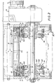
- the conveyor of the accumulation type comprises on a frame 8, two parallel traction chains spaced from each other 9, 10, passing over toothed end drums 11 wedged on a shaft 12 by means of locking rings 13.
- the aforementioned traction chains 9, 10, are driven in a conventional manner, by the motor 14 with reduction gear 15, and they are adapted to drive a plurality of shuttles indicated generally by NOT.
- the N shuttles are immobilized in suitable locations using stop devices which will not be described in detail since they are not part of the present invention.
- the shuttles N comprise on each lateral side a pair of toothed wheels 20, 21, capable of meshing, each pair, with a traction chain; the pairs of toothed wheels in question 20, 21, are wedged by means of a pin 24 with a transverse shaft 25 which is mounted freely rotating with gentle friction in the bearings 26 carried by the shuttle.
- each semi-circular end zone is equipped to allow positive drive of the shuttles while offering the possibility of stops if necessary.
- the two ends of the conveyor having a substantially similar construction, only one will be described in the following, the end described being that comprising the drive motor with its reducer, the toothed drums.
- the transverse shaft 12 already mentioned carries by means of bearings 30 a pair of supports each forming a grooved wheel 34 for the reception of a contact ring 33 of any material, for example semi-rigid synthetic.
- Each of the aforementioned grooved wheels 34 is adjacent to the toothed drums and, according to a preferred embodiment, it consists of two flanges 34A, 34B, assembled by screws 34C to a central body 34D by determining a substantially semi-circular groove 34E into which the contact ring 33 of semi-rigid synthetic material is inserted, said ring having a portion of its periphery projecting from the outer circular edge of the two flanges 34A, 34B.
- the ring extends approximately a quarter of its diameter beyond the aforementioned circular edges.
- the shuttles N each have, on their underside, on either side of a transverse plane of symmetry XX (FIG. 3), a first pair of pads 45, and a second pair of pads 46 which are therefore spaced longitudinally along the axis of movement of the shuttle, and transversely with an axis E in correspondence with the axis E1 formed by the contact rings 33, the pairs of pads being in fact constituted by bosses.
- XX transverse plane of symmetry
- the aforementioned bosses have (see in particular in FIG. 3) a free terminal surface substantially in the sector of a circle 49 crenellated in a transverse direction, this in order to promote adhesion with the ring.
- the semicircular ends of the raceways 27, that is to say the semicircular parts situated beyond a passing plane not the line AA in FIG. 3, are provided in the extension of the outer track 27A, with a track 50 forming a stop and a raceway with the rollers G supporting the shuttles, while the inner track 27B is partially interrupted after the above-mentioned plane AA, and taken up again by the presence of a circular guide sector 51.
- pitch diameter Dp of the end toothed drums 11 is slightly less than the outside diameter De of the contact rings 33.
- contact rings 33 can be full, hollow, and inflatable, made of synthetic material, hard rubber, etc.
- the ring support could be arranged to carry a series of parallel rings, while the bosses 45, 46, arranged on the underside would be arranged in correspondence.
- each shuttle N rotatably supports two transverse shafts 25 on which are respectively wedged two pairs of toothed wheels 20,21 which mesh the traction chains 9, 10, and at each end, each transverse shaft 25 rotatably supports a roller G, the diameter of these rollers being smaller than that of the gears 20,21.
- Each roller G rolls along a raceway comprising an outer track 27A and an inner track 27B defined on each straight section of the frame 8 of the conveyor.
- each straight section of the conveyor consists of a section section 50 which defines not only a raceway for the rollers G of the shuttles N, but also a guide track for the traction chains 9 , 10.
- each profile section 50 of the frame 8 has at least one housing 51 for receiving the rollers G and two housings 52, 52 ⁇ , facing each other, in which are mounted elements guide 60 for the traction chains 9, 10.
- the housing 51 is delimited by three walls of the profile section 50: a rectilinear side wall 51a extending perpendicularly to the shafts 25 of the shuttles N, and two rectilinear longitudinal walls 51b, 51c which extend at 90 °, and on the same side , the two longitudinal edges of the side wall 51a, respectively.
- the housing 52 is delimited by three walls of the profile section 50: a rectilinear side wall 52a substantially in the extension of the wall 51a of the housing 51, a rectilinear longitudinal wall constituted by the wall 51c of the housing 51, and a rectilinear longitudinal wall 52b extending parallel to the wall 51c and on the same side as the latter with respect to the side walls 51a, 52a.
- the housing 52 ⁇ is delimited by three walls of the profile section 50: a straight longitudinal wall 52 ⁇ b which extends the longitudinal wall 52b of the housing 52, a straight side wall 52 ⁇ a which extends the free end edge of the wall 52 ⁇ b at 90 ° parallel and facing the side wall 52a, and a straight longitudinal wall 52 ⁇ c substantially coplanar with the wall 51c separating the two housings 51, 52 and which extends at 90 ° the free end edge of the side wall 52 ⁇ a, in the direction of the wall 51c. Between the free end edges of the longitudinal walls 51c, 52 ⁇ c, a space e is defined for the free passage of the toothed rollers 20,21.
- the internal surfaces of the longitudinal walls 51b, 51c of the housing 51 form the aforementioned raceways 27A, 27B, respectively.
- the internal surface of the longitudinal wall 51c of each section of profile supports the weight of the shuttles N by means of the rollers G, this internal surface is covered with a coating.
- anti-wear 54 consisting of a metal strip such as a strip for example.
- This strip 54 is slid, at one end of the profile section 50, between the internal surface of the wall 51c and two parallel lateral ribs 55, 56.
- the rib 55 integrated into the profile section 50 is located on the side wall 51a of the housing 50, and the rib 56 is constituted by a flange provided on the free longitudinal side of the wall 51c.
- the strip 54 has several notches 56 on its longitudinal side adjacent to the wall 51a of the housing 51, as shown diagrammatically in FIG. 5. Locking means such as catches 57 are introduced into the through passages provided in the side wall 51a and engaged by their ends in the notches 56.
- Chain guide elements 60 are mounted in housing 52.52 ⁇ .
- Each guide element 60 is constituted by a section of profile made of synthetic material such as polystyrene for example.
- Each guide section 60 has a substantially C-shaped cross section with a side wall 60a and two longitudinal walls 60c and 60b which extend perpendicularly and on the same side of the lateral wall 60a.
- the outer faces of the walls 60a, 60b and 60c of each guide section 60 respectively come into contact with the inner faces of the walls 52a, 51c, 52b of the housing 52 and 52 ⁇ a, 52 ⁇ b, 52 ⁇ c of the housing 52 respectivement.
- the guide sections 60 are held in place by means of screws 70 which pass through passages provided in the side walls 52a and 52 ⁇ a of section sections 50.
- the free ends of the longitudinal edges 60b, 60c of each guide section 60 respectively have two internal edges 61 facing each other.
- Each guide section 60 freely introduced into the housings 52, 52 ⁇ of a profile section 50 is held in place by means of screws 70 mounted in passages provided through the side walls 52a, 52 ⁇ a.
- each traction chain 9, 10 is a chain of the multiple roller type, and more precisely a triple chain, known per se, comprising a central chain 9a and two side chains 9b.
- the teeth of the toothed wheels 20, 21 mesh with the central chain 9a, while the side chains 9b are positioned so that their rollers 9c come substantially into contact with the end surfaces of the flanges 61 of the guide sections 60, the chain links, lateral 9b respectively coming from either side of the guide flanges 61.
Landscapes
- Engineering & Computer Science (AREA)
- Mechanical Engineering (AREA)
- Chain Conveyers (AREA)
- Rollers For Roller Conveyors For Transfer (AREA)
Applications Claiming Priority (2)
| Application Number | Priority Date | Filing Date | Title |
|---|---|---|---|
| FR8611099 | 1986-07-31 | ||
| FR8611099A FR2602217B1 (fr) | 1986-07-31 | 1986-07-31 | Convoyeur du genre a accumulation |
Publications (2)
| Publication Number | Publication Date |
|---|---|
| EP0256926A1 true EP0256926A1 (de) | 1988-02-24 |
| EP0256926B1 EP0256926B1 (de) | 1990-10-10 |
Family
ID=9337916
Family Applications (1)
| Application Number | Title | Priority Date | Filing Date |
|---|---|---|---|
| EP87401796A Expired - Lifetime EP0256926B1 (de) | 1986-07-31 | 1987-07-31 | Stauförderer |
Country Status (4)
| Country | Link |
|---|---|
| EP (1) | EP0256926B1 (de) |
| DE (1) | DE3765500D1 (de) |
| ES (1) | ES2018841B3 (de) |
| FR (1) | FR2602217B1 (de) |
Cited By (18)
| Publication number | Priority date | Publication date | Assignee | Title |
|---|---|---|---|---|
| FR2630092A1 (fr) * | 1988-04-14 | 1989-10-20 | Sgie Ind Sa | Navette comportant un dispositif de freinage, associee a un convoyeur en pente pour l'accumulation de navettes |
| GB2221886A (en) * | 1988-08-16 | 1990-02-21 | Litton Automation Systems | Pallet conveying system |
| DE3836952A1 (de) * | 1988-10-29 | 1990-05-03 | Matthias Malatitsch | Palettenfoerderer |
| GB2235910A (en) * | 1989-09-15 | 1991-03-20 | Durr Automation Inc | Chain conveyor and pallet |
| US5009306A (en) * | 1989-06-19 | 1991-04-23 | Simplimatic Engineering Company | Printed circuit board conveyor and method |
| FR2660293A1 (fr) * | 1990-03-30 | 1991-10-04 | Sgie Ind Sa | Dispositif d'arret de navettes en zone de transition, pour un convoyeur a accumulation, et convoyeur muni de ce dispositf. |
| EP0462878A1 (de) * | 1990-06-21 | 1991-12-27 | Societe Anonyme Des Usines Farman | Stauförderer mit Arretiervorrichtung für Lastenträger am Übergangsbereich, Lastenträger und Lastenträgerzug für diese |
| EP0531610A1 (de) * | 1991-09-10 | 1993-03-17 | BARILLA G. e R. F.lli - Società per Azioni | Vorrichtung zum Fördern von Gegenständen, insbesondere verpackte Esswaren, von einer Ladestation zu einer Entladestation |
| US5240104A (en) * | 1992-01-31 | 1993-08-31 | Douglas John J | Printed circuit board belt conveyor |
| FR2711933A1 (fr) * | 1993-11-04 | 1995-05-12 | Mach Speciales Manutention | Magasin à accumulation, notamment pour une chaîne de fabrication ou d'usinage, pour alimenter un poste de travail en pièces ou en outils... . |
| GB2316665A (en) * | 1996-08-29 | 1998-03-04 | Western Atlas Int Inc | Accumulating conveyor with pallets driven by endless chain |
| EP0913345A1 (de) | 1997-10-31 | 1999-05-06 | Aries Packaging S.A. | Modulartiger Mehrweg-Stauförderer mit unter Last versenkbaren Antriebsriemen |
| US6086308A (en) * | 1997-08-13 | 2000-07-11 | Quipp Systems, Inc. | Cart handling system |
| DE102008045498A1 (de) * | 2008-09-03 | 2010-03-04 | Weets, Jakob | Stetigförderer mit wenigstens einem Gliederband |
| EP2189397A1 (de) * | 2008-11-25 | 2010-05-26 | Mathieu Tep | Lagerungsbehälter mit wieder verwendbaren Paletten |
| CN102126606A (zh) * | 2010-12-27 | 2011-07-20 | 江苏天奇物流系统工程股份有限公司 | 发动机分装线 |
| WO2015173406A1 (de) * | 2014-05-16 | 2015-11-19 | Bleichert Automation Gmbh & Co. Kg | Umlaufförderer |
| CN118850753A (zh) * | 2024-09-29 | 2024-10-29 | 山东康友光电科技股份有限公司 | 应用于玻璃生产的柔性输送系统 |
Families Citing this family (5)
| Publication number | Priority date | Publication date | Assignee | Title |
|---|---|---|---|---|
| DE9416115U1 (de) * | 1994-10-06 | 1995-08-03 | F+S Automationstechnik GmbH, 74229 Oedheim | Paletten-Stauförderer |
| DE102004019922A1 (de) | 2004-04-21 | 2004-11-18 | Bär, Ralf, Dipl.-Ing. | Fördersystem für Werkstücke oder Gegenstände |
| CN103693401A (zh) * | 2013-12-13 | 2014-04-02 | 安徽巨一自动化装备有限公司 | 积放式输送机摩擦翻转机构 |
| CN110127301B (zh) * | 2019-06-20 | 2020-11-10 | 山东中天盛科自动化设备有限公司 | 一种产品输送用具有定位功能的自动化流水线设备 |
| CN117416725B (zh) * | 2023-12-18 | 2024-02-13 | 宜宾本信电子科技有限公司 | 一种显示器组装输送装置 |
Citations (2)
| Publication number | Priority date | Publication date | Assignee | Title |
|---|---|---|---|---|
| DE3029620A1 (de) * | 1980-08-05 | 1982-03-18 | R. Tückmantel & D. Naber, Ingenieurbüro für Automatisierung, 4018 Langenfeld | Transporteinrichtung fuer werkstuecktraeger |
| US4431102A (en) * | 1981-08-28 | 1984-02-14 | Precision Automation Co., Inc. | Multi-station production conveyor |
Family Cites Families (1)
| Publication number | Priority date | Publication date | Assignee | Title |
|---|---|---|---|---|
| FR2576000B1 (fr) * | 1985-01-14 | 1990-06-01 | Peugeot | Convoyeur a chaines permettant d'accumuler des chariots sur un troncon du convoyeur |
-
1986
- 1986-07-31 FR FR8611099A patent/FR2602217B1/fr not_active Expired - Fee Related
-
1987
- 1987-07-31 ES ES87401796T patent/ES2018841B3/es not_active Expired - Lifetime
- 1987-07-31 EP EP87401796A patent/EP0256926B1/de not_active Expired - Lifetime
- 1987-07-31 DE DE8787401796T patent/DE3765500D1/de not_active Expired - Lifetime
Patent Citations (2)
| Publication number | Priority date | Publication date | Assignee | Title |
|---|---|---|---|---|
| DE3029620A1 (de) * | 1980-08-05 | 1982-03-18 | R. Tückmantel & D. Naber, Ingenieurbüro für Automatisierung, 4018 Langenfeld | Transporteinrichtung fuer werkstuecktraeger |
| US4431102A (en) * | 1981-08-28 | 1984-02-14 | Precision Automation Co., Inc. | Multi-station production conveyor |
Cited By (31)
| Publication number | Priority date | Publication date | Assignee | Title |
|---|---|---|---|---|
| FR2630092A1 (fr) * | 1988-04-14 | 1989-10-20 | Sgie Ind Sa | Navette comportant un dispositif de freinage, associee a un convoyeur en pente pour l'accumulation de navettes |
| GB2221886B (en) * | 1988-08-16 | 1992-05-27 | Litton Automation Systems | Improved conveying system |
| DE3918087A1 (de) * | 1988-08-16 | 1990-02-22 | Litton Automation Systems | Staufoerderer |
| FR2635508A1 (fr) * | 1988-08-16 | 1990-02-23 | Litton Ind Automation Sys | Transporteur accumulateur sans fin a voies superieure et inferieure |
| GB2221886A (en) * | 1988-08-16 | 1990-02-21 | Litton Automation Systems | Pallet conveying system |
| DE3836952A1 (de) * | 1988-10-29 | 1990-05-03 | Matthias Malatitsch | Palettenfoerderer |
| US5009306A (en) * | 1989-06-19 | 1991-04-23 | Simplimatic Engineering Company | Printed circuit board conveyor and method |
| GB2235910A (en) * | 1989-09-15 | 1991-03-20 | Durr Automation Inc | Chain conveyor and pallet |
| GB2235910B (en) * | 1989-09-15 | 1994-03-30 | Durr Automation Inc | Improvements in and relating to conveying |
| FR2660293A1 (fr) * | 1990-03-30 | 1991-10-04 | Sgie Ind Sa | Dispositif d'arret de navettes en zone de transition, pour un convoyeur a accumulation, et convoyeur muni de ce dispositf. |
| EP0462878A1 (de) * | 1990-06-21 | 1991-12-27 | Societe Anonyme Des Usines Farman | Stauförderer mit Arretiervorrichtung für Lastenträger am Übergangsbereich, Lastenträger und Lastenträgerzug für diese |
| EP0531610A1 (de) * | 1991-09-10 | 1993-03-17 | BARILLA G. e R. F.lli - Società per Azioni | Vorrichtung zum Fördern von Gegenständen, insbesondere verpackte Esswaren, von einer Ladestation zu einer Entladestation |
| US5240104A (en) * | 1992-01-31 | 1993-08-31 | Douglas John J | Printed circuit board belt conveyor |
| US5259495A (en) * | 1992-01-31 | 1993-11-09 | Simplimatic Engineering Company | Belt tensioner and turnover device for a printed circuit board belt conveyor |
| FR2711933A1 (fr) * | 1993-11-04 | 1995-05-12 | Mach Speciales Manutention | Magasin à accumulation, notamment pour une chaîne de fabrication ou d'usinage, pour alimenter un poste de travail en pièces ou en outils... . |
| GB2316665A (en) * | 1996-08-29 | 1998-03-04 | Western Atlas Int Inc | Accumulating conveyor with pallets driven by endless chain |
| GB2316665B (en) * | 1996-08-29 | 2000-06-21 | Western Atlas Int Inc | Endless accumulating conveyer |
| US6086308A (en) * | 1997-08-13 | 2000-07-11 | Quipp Systems, Inc. | Cart handling system |
| EP0913345A1 (de) | 1997-10-31 | 1999-05-06 | Aries Packaging S.A. | Modulartiger Mehrweg-Stauförderer mit unter Last versenkbaren Antriebsriemen |
| DE102008045498A1 (de) * | 2008-09-03 | 2010-03-04 | Weets, Jakob | Stetigförderer mit wenigstens einem Gliederband |
| EP2189397A1 (de) * | 2008-11-25 | 2010-05-26 | Mathieu Tep | Lagerungsbehälter mit wieder verwendbaren Paletten |
| FR2938829A1 (fr) * | 2008-11-25 | 2010-05-28 | Mathieu Tep | Magasin de stockage a palettes recyclables. |
| CN102126606B (zh) * | 2010-12-27 | 2012-12-05 | 江苏天奇物流系统工程股份有限公司 | 发动机分装线 |
| CN102126606A (zh) * | 2010-12-27 | 2011-07-20 | 江苏天奇物流系统工程股份有限公司 | 发动机分装线 |
| WO2015173406A1 (de) * | 2014-05-16 | 2015-11-19 | Bleichert Automation Gmbh & Co. Kg | Umlaufförderer |
| CN106458453A (zh) * | 2014-05-16 | 2017-02-22 | 布莱希特自动化有限责任公司 | 转动传送器 |
| US9758306B2 (en) | 2014-05-16 | 2017-09-12 | Bleichert Automation Gmbh & Co. Kg | Continuous conveyor |
| EP3560861A1 (de) * | 2014-05-16 | 2019-10-30 | Bleichert Automation Gmbh&Co. KG | Umlaufförderer |
| CN106458453B (zh) * | 2014-05-16 | 2019-12-06 | 布莱希特自动化有限责任公司 | 转动传送器 |
| CN110562665A (zh) * | 2014-05-16 | 2019-12-13 | 布莱希特自动化有限责任公司 | 转动传送器 |
| CN118850753A (zh) * | 2024-09-29 | 2024-10-29 | 山东康友光电科技股份有限公司 | 应用于玻璃生产的柔性输送系统 |
Also Published As
| Publication number | Publication date |
|---|---|
| FR2602217B1 (fr) | 1993-09-24 |
| DE3765500D1 (de) | 1990-11-15 |
| FR2602217A1 (fr) | 1988-02-05 |
| EP0256926B1 (de) | 1990-10-10 |
| ES2018841B3 (es) | 1991-05-16 |
Similar Documents
| Publication | Publication Date | Title |
|---|---|---|
| EP0256926B1 (de) | Stauförderer | |
| EP0084511B1 (de) | Bandförderer | |
| FR2635508A1 (fr) | Transporteur accumulateur sans fin a voies superieure et inferieure | |
| FR2713190A1 (fr) | Structure de chenille. | |
| FR2596947A1 (fr) | Dispositif d'avance pour deplacement le long d'un tronc d'arbre | |
| EP0468841B1 (de) | Bandförderer | |
| EP0803464A1 (de) | Übertragungsvorrichtung, insbesondere für Fussgänger, zwischen zwei nacheinander in Reihe angeordneten, Förderungselementen, und Fördervorrichtung mit solcher Vorrichtung ausgestattet | |
| EP1044870B1 (de) | Verbessertes Antriebsrad für Gummigleiskette | |
| FR2999217A1 (fr) | Installation de convoyage de vehicules automobiles a transmission d'efforts equilibree | |
| FR2530590A1 (fr) | Convoyeur helicoidal a rouleaux coniques entraines par courroie | |
| EP0527663A1 (de) | Vorrichtung zum Fördern von Werkstücken von einer Arbeitsstation zu einer anderen, entlang einer Behandlungslinie | |
| FR2626858A1 (fr) | Perfectionnement aux convoyeurs du genre a accumulation | |
| FR2658771A1 (fr) | Plaque tournante perfectionnee pour vehicule automobile. | |
| EP0337891A1 (de) | Stauförderer mit Neigung für einen durch Endlosketten angetriebenen Lastenträger | |
| CA2494426C (fr) | Convoyeur | |
| EP0449706A1 (de) | Handhabungssystem für Gegenstände | |
| FR2773790A1 (fr) | Rouleau de guidage pour bandes transporteuses | |
| FR2753679A1 (fr) | Dispositif deflecteur de materiaux pour une chaine de traction | |
| WO1980002060A1 (fr) | Courroie trapezoidale armee a contacts metalliques | |
| EP0013531B1 (de) | Rollgang für die Handhabung von Waren | |
| FR2583024A1 (fr) | Transporteur du type " carrousel ". | |
| FR2554100A1 (fr) | Assemblage de galets a usage universel pour un appareil de transport, notamment un escalier roulant | |
| EP0696976B1 (de) | Raupenkette mit einem band aus biegsamem material für ein fahrzeug | |
| FR2495585A1 (fr) | Convoyeur a poussoirs ou racleurs | |
| EP1260461B1 (de) | Tragelement eines Bandförderers und Förderer mit einem solchen Element |
Legal Events
| Date | Code | Title | Description |
|---|---|---|---|
| PUAI | Public reference made under article 153(3) epc to a published international application that has entered the european phase |
Free format text: ORIGINAL CODE: 0009012 |
|
| AK | Designated contracting states |
Kind code of ref document: A1 Designated state(s): BE DE ES FR GB IT LU NL SE |
|
| 17P | Request for examination filed |
Effective date: 19880321 |
|
| 17Q | First examination report despatched |
Effective date: 19890307 |
|
| RAP1 | Party data changed (applicant data changed or rights of an application transferred) |
Owner name: S G I E INDUSTRIES S.A. |
|
| GRAA | (expected) grant |
Free format text: ORIGINAL CODE: 0009210 |
|
| AK | Designated contracting states |
Kind code of ref document: B1 Designated state(s): BE DE ES FR GB IT LU NL SE |
|
| REF | Corresponds to: |
Ref document number: 3765500 Country of ref document: DE Date of ref document: 19901115 |
|
| ITF | It: translation for a ep patent filed | ||
| GBT | Gb: translation of ep patent filed (gb section 77(6)(a)/1977) | ||
| ITTA | It: last paid annual fee | ||
| PG25 | Lapsed in a contracting state [announced via postgrant information from national office to epo] |
Ref country code: LU Free format text: LAPSE BECAUSE OF NON-PAYMENT OF DUE FEES Effective date: 19910731 |
|
| PLBE | No opposition filed within time limit |
Free format text: ORIGINAL CODE: 0009261 |
|
| STAA | Information on the status of an ep patent application or granted ep patent |
Free format text: STATUS: NO OPPOSITION FILED WITHIN TIME LIMIT |
|
| 26N | No opposition filed | ||
| EAL | Se: european patent in force in sweden |
Ref document number: 87401796.5 |
|
| REG | Reference to a national code |
Ref country code: GB Ref legal event code: IF02 |
|
| PGFP | Annual fee paid to national office [announced via postgrant information from national office to epo] |
Ref country code: SE Payment date: 20020724 Year of fee payment: 16 |
|
| PG25 | Lapsed in a contracting state [announced via postgrant information from national office to epo] |
Ref country code: SE Free format text: LAPSE BECAUSE OF NON-PAYMENT OF DUE FEES Effective date: 20030801 |
|
| EUG | Se: european patent has lapsed | ||
| PGFP | Annual fee paid to national office [announced via postgrant information from national office to epo] |
Ref country code: IT Payment date: 20060731 Year of fee payment: 20 |
|
| PGFP | Annual fee paid to national office [announced via postgrant information from national office to epo] |
Ref country code: GB Payment date: 20060818 Year of fee payment: 20 |
|
| PGFP | Annual fee paid to national office [announced via postgrant information from national office to epo] |
Ref country code: BE Payment date: 20060823 Year of fee payment: 20 |
|
| PGFP | Annual fee paid to national office [announced via postgrant information from national office to epo] |
Ref country code: ES Payment date: 20060831 Year of fee payment: 20 |
|
| PGFP | Annual fee paid to national office [announced via postgrant information from national office to epo] |
Ref country code: DE Payment date: 20060907 Year of fee payment: 20 |
|
| PGFP | Annual fee paid to national office [announced via postgrant information from national office to epo] |
Ref country code: NL Payment date: 20060921 Year of fee payment: 20 |
|
| PG25 | Lapsed in a contracting state [announced via postgrant information from national office to epo] |
Ref country code: NL Free format text: LAPSE BECAUSE OF EXPIRATION OF PROTECTION Effective date: 20070731 |
|
| REG | Reference to a national code |
Ref country code: GB Ref legal event code: PE20 |
|
| NLV7 | Nl: ceased due to reaching the maximum lifetime of a patent |
Effective date: 20070731 |
|
| REG | Reference to a national code |
Ref country code: ES Ref legal event code: FD2A Effective date: 20070801 |
|
| PG25 | Lapsed in a contracting state [announced via postgrant information from national office to epo] |
Ref country code: GB Free format text: LAPSE BECAUSE OF EXPIRATION OF PROTECTION Effective date: 20070730 |
|
| BE20 | Be: patent expired |
Owner name: S.A. *SGIE INDUSTRIES Effective date: 20070731 |
|
| PG25 | Lapsed in a contracting state [announced via postgrant information from national office to epo] |
Ref country code: ES Free format text: LAPSE BECAUSE OF EXPIRATION OF PROTECTION Effective date: 20070801 |
|
| PGFP | Annual fee paid to national office [announced via postgrant information from national office to epo] |
Ref country code: FR Payment date: 20070131 Year of fee payment: 20 |