EP0527663A1 - Vorrichtung zum Fördern von Werkstücken von einer Arbeitsstation zu einer anderen, entlang einer Behandlungslinie - Google Patents
Vorrichtung zum Fördern von Werkstücken von einer Arbeitsstation zu einer anderen, entlang einer Behandlungslinie Download PDFInfo
- Publication number
- EP0527663A1 EP0527663A1 EP92401999A EP92401999A EP0527663A1 EP 0527663 A1 EP0527663 A1 EP 0527663A1 EP 92401999 A EP92401999 A EP 92401999A EP 92401999 A EP92401999 A EP 92401999A EP 0527663 A1 EP0527663 A1 EP 0527663A1
- Authority
- EP
- European Patent Office
- Prior art keywords
- belt
- pallet
- track
- lever
- heavy
- Prior art date
- Legal status (The legal status is an assumption and is not a legal conclusion. Google has not performed a legal analysis and makes no representation as to the accuracy of the status listed.)
- Withdrawn
Links
- 230000008878 coupling Effects 0.000 claims abstract description 16
- 238000010168 coupling process Methods 0.000 claims abstract description 16
- 238000005859 coupling reaction Methods 0.000 claims abstract description 16
- 238000005096 rolling process Methods 0.000 claims abstract description 8
- 230000000284 resting effect Effects 0.000 claims abstract description 5
- 230000005484 gravity Effects 0.000 claims abstract description 4
- 238000006073 displacement reaction Methods 0.000 claims abstract 2
- 238000005303 weighing Methods 0.000 claims description 4
- 238000012545 processing Methods 0.000 claims description 2
- 239000006096 absorbing agent Substances 0.000 claims 1
- 230000035939 shock Effects 0.000 claims 1
- 230000000694 effects Effects 0.000 description 4
- 238000009825 accumulation Methods 0.000 description 2
- 230000000712 assembly Effects 0.000 description 2
- 238000000429 assembly Methods 0.000 description 2
- 238000009434 installation Methods 0.000 description 2
- 239000000463 material Substances 0.000 description 2
- 238000000034 method Methods 0.000 description 2
- 230000006978 adaptation Effects 0.000 description 1
- 230000005540 biological transmission Effects 0.000 description 1
- 230000000903 blocking effect Effects 0.000 description 1
- 238000013016 damping Methods 0.000 description 1
- 238000010586 diagram Methods 0.000 description 1
- 238000007599 discharging Methods 0.000 description 1
- 229920001971 elastomer Polymers 0.000 description 1
- 239000000806 elastomer Substances 0.000 description 1
- 238000009432 framing Methods 0.000 description 1
- 238000012423 maintenance Methods 0.000 description 1
- 230000007246 mechanism Effects 0.000 description 1
- 238000007747 plating Methods 0.000 description 1
- 238000003825 pressing Methods 0.000 description 1
- 238000004064 recycling Methods 0.000 description 1
- 238000012549 training Methods 0.000 description 1
- 238000013519 translation Methods 0.000 description 1
- 238000010977 unit operation Methods 0.000 description 1
- 238000012795 verification Methods 0.000 description 1
Images

Classifications
-
- B—PERFORMING OPERATIONS; TRANSPORTING
- B65—CONVEYING; PACKING; STORING; HANDLING THIN OR FILAMENTARY MATERIAL
- B65G—TRANSPORT OR STORAGE DEVICES, e.g. CONVEYORS FOR LOADING OR TIPPING, SHOP CONVEYOR SYSTEMS OR PNEUMATIC TUBE CONVEYORS
- B65G19/00—Conveyors comprising an impeller or a series of impellers carried by an endless traction element and arranged to move articles or materials over a supporting surface or underlying material, e.g. endless scraper conveyors
- B65G19/02—Conveyors comprising an impeller or a series of impellers carried by an endless traction element and arranged to move articles or materials over a supporting surface or underlying material, e.g. endless scraper conveyors for articles, e.g. for containers
-
- B—PERFORMING OPERATIONS; TRANSPORTING
- B23—MACHINE TOOLS; METAL-WORKING NOT OTHERWISE PROVIDED FOR
- B23Q—DETAILS, COMPONENTS, OR ACCESSORIES FOR MACHINE TOOLS, e.g. ARRANGEMENTS FOR COPYING OR CONTROLLING; MACHINE TOOLS IN GENERAL CHARACTERISED BY THE CONSTRUCTION OF PARTICULAR DETAILS OR COMPONENTS; COMBINATIONS OR ASSOCIATIONS OF METAL-WORKING MACHINES, NOT DIRECTED TO A PARTICULAR RESULT
- B23Q7/00—Arrangements for handling work specially combined with or arranged in, or specially adapted for use in connection with, machine tools, e.g. for conveying, loading, positioning, discharging, sorting
- B23Q7/14—Arrangements for handling work specially combined with or arranged in, or specially adapted for use in connection with, machine tools, e.g. for conveying, loading, positioning, discharging, sorting co-ordinated in production lines
- B23Q7/1426—Arrangements for handling work specially combined with or arranged in, or specially adapted for use in connection with, machine tools, e.g. for conveying, loading, positioning, discharging, sorting co-ordinated in production lines with work holders not rigidly fixed to the transport devices
- B23Q7/1447—Arrangements for handling work specially combined with or arranged in, or specially adapted for use in connection with, machine tools, e.g. for conveying, loading, positioning, discharging, sorting co-ordinated in production lines with work holders not rigidly fixed to the transport devices using endless conveyors
- B23Q7/1452—Arrangements for handling work specially combined with or arranged in, or specially adapted for use in connection with, machine tools, e.g. for conveying, loading, positioning, discharging, sorting co-ordinated in production lines with work holders not rigidly fixed to the transport devices using endless conveyors comprising load-supporting surfaces
Definitions
- the present invention relates to the technique of flat conveyors with adaptable geometry commonly called flexible workshops, which are used to serve several work stations for a part or an assembly comprising, for example stations for mounting components on a base, stations verification, these stations can be automatic or manual, between a supply station of the line along which the stations are arranged and a station for discharging finished parts or assemblies.
- an assembly line (for example) comprises a main conveyor in the form of a loop closed to which grafts are grafted which serve one or more specific stations.
- the branches can themselves constitute a loop on which secondary branches are grafted.
- the main transporter makes it possible to orient each part directly to the bypass concerned, bypassing those which are not concerned by the treatment of the part in question, and constitutes a recycling loop at the level of which it is possible to manage the buffer stocks and the differences between the cycle times of each unit operation on the line.
- the parts or assemblies to be treated are most of the time placed on transport pallets which are moved and guided on a fixed track, generally made from standardized and modular elements, which allows adaptations of the shape of the track, either in the configuration of the places intended to accommodate the line, or in the evolution of needs and the number of stations installed along the line.
- the pallet drive along the track is ensured by one or two chains (gall) or one or two belts which cooperate by friction with each pallet.
- the friction force is low enough that the movement of the chain or belt is not hindered in the areas where the pallets stop and accumulate.
- the invention therefore relates to a device for moving parts from one station to another along a line for processing these parts, comprising a track serving the stations of the line, a plurality of pallets rolling on the track, the track and the pallets comprising guide means cooperating with each other, the track being bordered by at least one marginal drive belt, characterized in that the pallet comprises on at least one its sides a member of its coupling to the belt comprising at least one heavy element resting by gravity on the belt so that a movement of this belt relative to the pallet frictionally generates a movement of this heavy element triggering the clutch of the member for coupling the pallet to the belt.
- the device of the invention uses the friction between belt and pallet only to control the clutch. Friction is therefore a control means, the transmission power is transmitted by the means of the clutch itself, which are the power means of the installation.
- the coupling member comprises, directly above the weighing element, a surface integral with the pallet on which the belt slides, the heavy element constituting a self-locking tightening element of the belt against the surface. secured to the pallet.
- the weighing element is constituted by a heavy clamping shoe resting on the belt by a lower surface and comprising, opposite this surface, a slope inclined downward in the direction of movement of the belt and sliding on a fixed stop of the palette.
- the heavy element is constituted by a circular clamping cam articulated eccentrically on the pallet around an axis parallel to the sliding surface of the belt.
- a pallet In order not to limit the use of a pallet according to the invention, it comprises on each side, two heavy elements arranged in opposition so as to cause the coupling of the coupling of the pallet to the belt in both direction of movement of the latter.
- the coupling member is constituted by a pendulum lever articulated to the pallet above the belt with a play in the length direction of the lever, the latter comprising, at opposite to its articulation, a groove for the passage of the belt, the upper face of which rests on this belt and the lower face of which forms a cam for blocking the lever on the belt when the latter causes the pivoting of the belt by friction. the sink.
- the latter comprises disengaging members of the belt-pallet link, comprising a pusher bearing on each heavy element, mounted to slide in the pallet parallel to the direction of the belt and protruding beyond the front edge of the pallet, in its direction of movement when the heavy element is kept displaced by the belt.
- a variant of the declutching means of the belt pallet link, for a hitching member in the form of a pendulum lever, resides in the fact that the groove for the passage of the belt is delimited by the external surface of two rollers mounted in rotation braked on the pendulum lever.
- the belt pinched in the pendulum lever causes the rotation of two rollers which undergo a motor torque greater than the braking torque.
- the pallet is substantially square and has a pendulum lever in the center of each of its sides.
- the drive of the pallet can then pass indifferently from one margin to the other thereof.
- the positioning of the pallet on the track does not have to be preoriented either.
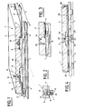
- Figures 1 to 7 illustrate various mechanisms for the cooperation of a workpiece pallet 1 with a cylindrical drive belt.
- the pallet 1 is represented schematically by a plate 3 equipped with rolling members 4 on a track 2 having two rolling tracks 5 and 6.
- This track belongs to an infrastructure not shown which also includes means for support and drive belts along at least one side of the track. The track is thus bordered on one side or, for certain sections, on both sides of a drive member with which each pallet can cooperate to be moved along the track which serves each of the treatment stations to which must be presented the palette.
- this belt is only represented by its active strand 7.
- FIGS. 1 and 2 The cooperation of the pallet 1 with the belt strand 7 is carried out, in FIGS. 1 and 2, by means of clutch pad 8.
- Each side 9 of the pallet as shown in FIG. 2 which is a section through the plane 11 of FIG. 1, has a sole 10 on which the belt strand 7 rests.
- the plate 3 overhangs this sole and has, at the base of the belt strand 7, a groove 11 in which the shoe 8 is slidably mounted.
- This shoe rests by its own weight on the strand 7 and has for this purpose a lower surface 12 whose profile is in an arc.
- the upper surface 13 of the shoe 8 is inclined.
- the groove or housing 11 has opposite this surface 13 a cylindrical rod 14 on which the surface 13 can bear depending on its position in the housing 11 between two stops 15 and 16. If, in Figure 1, the belt strand moves to the left, according to arrow A, it causes the pad 8 by friction in the same direction which comes to form a wedge between the rod 14 and the strand 7.
- the pallet 1 is then coupled to the strand 7 which drives it positively. This connection is self-locking because the greater the force exerted by the belt on the pallet, the greater the force of pinching the strand 7 between the pad 8 and the sole 10.
- Unlocking or disengaging this link can take place in two ways. If the path of the pallet deviates from that of the belt, by the effect of means for guiding this pallet integral with track 5, the belt can escape laterally from the clamp. The second way to disengage the link is to move the wedge back. This effect is obtained by a pusher 17 when the latter is pressed into the pallet 1 while meeting a fixed stop relative to the track or a previous pallet in a zone d 'accumulation.
- the pallet comprises along each of its sides two pads in opposition so as to be able to cooperate with a belt whatever its direction of movement.
- the variant embodiment of FIG. 3 comprises, in place of each of the pads of the preceding figures, a cam 18 constituted by a disc articulated eccentrically to the pallet 1.
- the effect of gravity keeps this disc in contact with the strand belt 7.
- the distance separating the axis 19 of articulation of this disk from the belt strand 7 is less than that separating this axis from the edge of the disk which is diametrically opposite to it.
- This cam therefore ensures the connection from the pallet to the belt strand 7 by jamming the latter.
- a push finger 17 can push the disc 18 back if it is pressed inside the pallet.
- the outer profile of the disc 18 will advantageously be of the same shape as that of the pads described above to allow lateral escape of the belt strand during a divergence between the paths of the belt and the pallet.
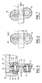
- FIG. 4 is an illustration of another alternative embodiment of the coupling means provided between the pallet and the belt drive strand.
- the pallet is equipped in the center of each of its sides with a pendulum lever 20 articulated to the pallet by means of a fixed axis 21 housed in a slot 22 of the lever 20.
- the latter At the end of the lever opposite to the slot 22 the latter has a groove 23 open laterally and delimited by two upper 24 and lower 25, convex surfaces, the minimum spacing of which is slightly greater than the diameter of the belt strand 7.
- the pendulum lever rests on the strand 7 by the upper surface 24 of the groove 23, the axis 21 being housed on the side of the lower end of the slot 22.
- the movement of the belt in direction A tends to rotate the lever 20 to the right of FIG. 4 around the axis 21.
- the surface 25 then comes to bear on the belt 7.
- a single pendulum lever is suitable for driving the pallet in two opposite directions.
- Flaps 28, 29 articulated on the front edges of the pallet offer an external surface extended over the entire front width of the pallet to receive the pushing force and transmit it to the corresponding push finger.
- FIGS. 5, 6 and 7. are means similar to those in FIG. 4, that is to say comprising a pendulum lever 20
- the plate 3 receives, by screws 30, a housing 31 which forms, by its walls 32 and 33, a clevis of articulation of the lever 20.
- the axis 34 of articulation is materialized by pins 35 a and 35 b which are housed in lights 36 and 37 of the yoke so that the lever 20 has, in addition to the possibility of oscillating in the yoke, freedom in vertical translation.
- the pins 35 a and 35 b form the end of an axis 38, integral with the lever 20 and on which a roller 39 is journalled.
- a friction lining 40 is placed between the roller 39 and the lever 20.
- a spring leaf 41 has the function of generating a plating effect on this lining 40, fixed in rotation on the lever 20, against the side of the roller and consequently a permanent resistant torque on the roller. The roller can therefore only rotate if it undergoes a drive torque overcoming this resistant torque.
- a second roller 42 is mounted in the same way at the free end of the pendulum lever 20 (on an axis 43 with friction lining 44 and spring 45), the distance separating the two rollers being slightly greater than the diameter of the strand 7 of belt which is housed between them.
- the profile of the outer surface of the rollers 39 and 42 is such that it does not oppose the lateral escape of the belt (direction B in Figure 5).
- FIGS. 6 and 7 are front diagrams of the lever 20. In FIG. 6, the belt 7 is stationary and the lever 20 rests on the belt by the lower point P of the roller 39.
- the resistant torque of the rollers on the lever can be exerted by a magnetic field avoiding the friction of two opposing faces.
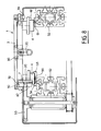
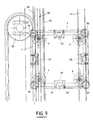
- Figures 8, 9 and 10 illustrate by partial views the device as a whole, that is to say the pallet placed on a fixed structure supporting the track of the pallet, the fixed members for guiding them and the belt supports and their drive motors.
- FIGS. 8 and 9 which are respectively a partial transverse section of the device and a partial top view, it can be seen that the raceways 50, 51 of the pallet 1 are carried by the profiled beams 52 which are themselves integral with legs not shown and braced to constitute (in a modular way or not) a frame.
- the sections 52 also form the support for pulleys 53 for returning the endless belts which have their motor strand 7 in the vicinity of that of the raceways 50 or 51, which is bordered by a unilateral guide rail of the pallet.
- This rail is constituted by flanges 54, 55 of the path 50 which surround the supports of the rolling members 4 which form guide fingers.
- the guide rail can be replaced by two opposite guides each comprising a single flange.
- the pallets 1 have at each of their angles a roller 56 with a vertical axis which projects beyond the sides of the angle and which is made of damping material such as an elastomer.
- FIG. 10 a part of the device of the invention is shown which comprises a branch between a main traffic lane referenced 60 and a bypass lane 61, the direction of movement of the pallets being denoted C.
- a pallet approaching this branching from the right side of the figure is first taken up by the strand 67 of the belt 70 and oriented in the track 60 or the track 61 according to the position of a steering needle 62.
- This needle is articulated at 63 by one of its ends around a vertical axis perpendicular to the track and is maneuvered around this axis by means of a jack 64. It has a rectilinear side 65 and a curvilinear side 66. In its position of the figure, the curvilinear side 66 is active and forms the continuity of the rim 68 a of the rail 68.
- a belt 71 is located inside the curve defined by the edge 66 of the needle 62.
- the pallet driven by the belt strand 67, also cooperates with its lateral side opposite to that close to the strand 67 with the belt 71.
- the rolling members 4 located on this same side are then forced to follow the curve 66 while the guide rail 72 adjacent to the strand 67 has an interruption 73 to let escape the guide members of the pallet with which it cooperates.
- the needle 62 is folded down in the direction of the belt 71 so that its rectilinear side 65 comes in extension of the edge 68 b of the rail 68.
- the pallet remains in engagement with the strand 67 even if by its opposite lateral edge it cooperates briefly with the belt 71.
- the rail 68 extended by the rim 65 of the needle guides the pallet during its passage from the zone 73 devoid of rail of the side of the belt strand 67. The pallet then continues in the track 60 guided by the rail 72.
- the needle 62 will be a mad needle without a jack 64.
- a pallet arriving from the track 61 supported by the belt 71 will push the needle 67 back into its represented position (if it was not already there).
- a pallet arriving from track 60 will push back the mad needle 62 by pressing on its rectilinear side 65 and can continue its journey in the direction of the right of the figure.
- the active belt strands are, in the curves, situated inside of them and deflected by means of a plurality of rollers 77 consecutive arranged along a curve which does not is not an arc of a circle to correspond to the non-circular trajectory of the levers 20 for coupling each pallet to the belts.
Landscapes
- Engineering & Computer Science (AREA)
- Mechanical Engineering (AREA)
- Automatic Assembly (AREA)
Applications Claiming Priority (2)
| Application Number | Priority Date | Filing Date | Title |
|---|---|---|---|
| FR9109031 | 1991-07-17 | ||
| FR9109031A FR2679164B1 (fr) | 1991-07-17 | 1991-07-17 | Dispositif pour deplacer des pieces d'un poste a un autre le long d'une ligne de leur traitement. |
Publications (1)
| Publication Number | Publication Date |
|---|---|
| EP0527663A1 true EP0527663A1 (de) | 1993-02-17 |
Family
ID=9415227
Family Applications (1)
| Application Number | Title | Priority Date | Filing Date |
|---|---|---|---|
| EP92401999A Withdrawn EP0527663A1 (de) | 1991-07-17 | 1992-07-09 | Vorrichtung zum Fördern von Werkstücken von einer Arbeitsstation zu einer anderen, entlang einer Behandlungslinie |
Country Status (3)
| Country | Link |
|---|---|
| US (1) | US5222587A (de) |
| EP (1) | EP0527663A1 (de) |
| FR (1) | FR2679164B1 (de) |
Cited By (1)
| Publication number | Priority date | Publication date | Assignee | Title |
|---|---|---|---|---|
| NL1015315C2 (nl) * | 2000-05-26 | 2001-11-27 | Integrated Production And Test | Transportinrichting voor op productdragers geplaatste producten. |
Families Citing this family (14)
| Publication number | Priority date | Publication date | Assignee | Title |
|---|---|---|---|---|
| US5398802A (en) * | 1993-09-27 | 1995-03-21 | Simplimatic Engineering Company | Pallet conveyor and method of conveying pallets |
| AT411036B (de) * | 1997-11-24 | 2003-09-25 | Sticht Walter | Anlage zur bearbeitung und bzw. oder montage von bauteilen |
| JP2000142934A (ja) * | 1998-11-16 | 2000-05-23 | Tsubakimoto Chain Co | 長尺物体搬送用ローラコンベヤ |
| US6102194A (en) * | 1999-02-16 | 2000-08-15 | Belcan Corporation | Pallet type transfer device |
| DE19934866A1 (de) * | 1999-07-24 | 2001-01-25 | Bosch Gmbh Robert | Werkstückträger, insbesondere für manuelle Förderbahnen |
| JP3615095B2 (ja) * | 1999-09-21 | 2005-01-26 | 株式会社椿本チエイン | 自動車製造ライン用フリクション駆動式フロアーコンベヤ |
| US6464066B2 (en) * | 2000-04-04 | 2002-10-15 | Inno-Veyor, Inc. | Conveyor assembly with pallet coupling |
| DE50103205D1 (de) * | 2000-12-18 | 2004-09-16 | Ferag Ag | Schienenführbares Fördermittel und Fördersystem |
| FR2819497B1 (fr) | 2001-01-15 | 2003-08-08 | Prodel Holding | Installation pour la circulation de palettes porte-pieces et palette pour cette installation |
| GB2394931B (en) * | 2001-07-24 | 2005-05-11 | Honda Motor Co Ltd | Workpiece feeding apparatus |
| DE10201841A1 (de) * | 2002-01-16 | 2003-07-24 | Minitec Maschb Gmbh & Co Kg | Palette zum Transport von Gütern auf einem Förderband |
| DE102007040908A1 (de) * | 2007-08-30 | 2009-05-28 | Ceratis Gmbh | Friktionsfördersystem sowie Werkstückträger für Friktionsfördersystem |
| DE102008062357B4 (de) * | 2008-12-18 | 2010-10-28 | Ceratis Gmbh | Werkstückträgereinrichtung |
| DE102009008711A1 (de) * | 2009-02-12 | 2010-08-26 | Ceratis Gmbh | Fördersystem |
Citations (11)
| Publication number | Priority date | Publication date | Assignee | Title |
|---|---|---|---|---|
| DE217982C (de) * | ||||
| FR383379A (fr) * | 1907-10-28 | 1908-03-06 | Lamson Cons Store Service Comp | Perfectionnements dans les appareils convoyeurs |
| US1355860A (en) * | 1920-05-01 | 1920-10-19 | Snesrud Albert | Trip for manure-carriers |
| US2740515A (en) * | 1953-04-06 | 1956-04-03 | Williams & Wilson Ltd | Conveyor apparatus |
| US3099228A (en) * | 1961-10-12 | 1963-07-30 | Lingg Gerhard | Transport and storage arrangement for carriers |
| US3312330A (en) * | 1963-08-30 | 1967-04-04 | Juengel V Matic Systems Inc | Conveyor apparatus |
| DE1267608B (de) * | 1966-07-04 | 1968-05-02 | Siemens Ag | Foerderanlage, insbesondere Kastenfoerderanlage, zur Befoerderung von Foerderbehaeltern in Fahrrinnen |
| DE2407847A1 (de) * | 1974-02-19 | 1975-09-04 | Bosch Gmbh Robert | Fuer fliessfertigung bestimmte foerderbahn mit einem endlosen foerderband |
| EP0161412A1 (de) * | 1984-03-12 | 1985-11-21 | LIEBHERR-VERZAHNTECHNIK GmbH | Transportvorrichtung zum Fördern von Werkstückträgern |
| US4724951A (en) * | 1984-10-18 | 1988-02-16 | Nitto Seiko Co., Ltd. | Device for adjusting adhesive friction between pallet and endless chain in a pallet type multi-station conveyor |
| EP0319674A1 (de) * | 1987-11-06 | 1989-06-14 | Siemens Aktiengesellschaft | Handhabungssystem für Werkstückträger |
Family Cites Families (7)
| Publication number | Priority date | Publication date | Assignee | Title |
|---|---|---|---|---|
| FR1522489A (fr) * | 1967-03-15 | 1968-04-26 | Attache débrayable pour installations de transport ou de remorquage par câble aérien | |
| FR2327899A1 (fr) * | 1975-10-17 | 1977-05-13 | Automatisme & Technique | Systeme de transport continu sur voie ferree |
| JPS5376102A (en) * | 1976-12-20 | 1978-07-06 | Taiheiyo Eng | Shifting device of operator |
| FR2522566B2 (fr) * | 1982-03-05 | 1986-06-13 | Prodel Maurice | Dispositif d'entrainement a courroie pour palettes d'une machine pour l'assemblage ou l'usinage de pieces |
| SU1299874A1 (ru) * | 1985-10-15 | 1987-03-30 | Государственный Проектный И Конструкторский Институт "Союзпроммеханизация" | Устройство дл аварийного торможени транспортного средства подвесной канатной дороги |
| CA1253445A (en) * | 1988-01-06 | 1989-05-02 | Robert G. Ladouceur | Tow rope grabber |
| FR2638694B1 (fr) * | 1988-11-10 | 1991-08-02 | Ism Equipements Indls Montage | Installation de transfert comportant un circuit ferme de rails |
-
1991
- 1991-07-17 FR FR9109031A patent/FR2679164B1/fr not_active Expired - Fee Related
-
1992
- 1992-07-09 EP EP92401999A patent/EP0527663A1/de not_active Withdrawn
- 1992-07-17 US US07/914,462 patent/US5222587A/en not_active Expired - Fee Related
Patent Citations (11)
| Publication number | Priority date | Publication date | Assignee | Title |
|---|---|---|---|---|
| DE217982C (de) * | ||||
| FR383379A (fr) * | 1907-10-28 | 1908-03-06 | Lamson Cons Store Service Comp | Perfectionnements dans les appareils convoyeurs |
| US1355860A (en) * | 1920-05-01 | 1920-10-19 | Snesrud Albert | Trip for manure-carriers |
| US2740515A (en) * | 1953-04-06 | 1956-04-03 | Williams & Wilson Ltd | Conveyor apparatus |
| US3099228A (en) * | 1961-10-12 | 1963-07-30 | Lingg Gerhard | Transport and storage arrangement for carriers |
| US3312330A (en) * | 1963-08-30 | 1967-04-04 | Juengel V Matic Systems Inc | Conveyor apparatus |
| DE1267608B (de) * | 1966-07-04 | 1968-05-02 | Siemens Ag | Foerderanlage, insbesondere Kastenfoerderanlage, zur Befoerderung von Foerderbehaeltern in Fahrrinnen |
| DE2407847A1 (de) * | 1974-02-19 | 1975-09-04 | Bosch Gmbh Robert | Fuer fliessfertigung bestimmte foerderbahn mit einem endlosen foerderband |
| EP0161412A1 (de) * | 1984-03-12 | 1985-11-21 | LIEBHERR-VERZAHNTECHNIK GmbH | Transportvorrichtung zum Fördern von Werkstückträgern |
| US4724951A (en) * | 1984-10-18 | 1988-02-16 | Nitto Seiko Co., Ltd. | Device for adjusting adhesive friction between pallet and endless chain in a pallet type multi-station conveyor |
| EP0319674A1 (de) * | 1987-11-06 | 1989-06-14 | Siemens Aktiengesellschaft | Handhabungssystem für Werkstückträger |
Cited By (2)
| Publication number | Priority date | Publication date | Assignee | Title |
|---|---|---|---|---|
| NL1015315C2 (nl) * | 2000-05-26 | 2001-11-27 | Integrated Production And Test | Transportinrichting voor op productdragers geplaatste producten. |
| EP1157780A1 (de) * | 2000-05-26 | 2001-11-28 | Integrated Production and Test Engineering N.V. | System zum Fördern von Produkten auf Produktträgern |
Also Published As
| Publication number | Publication date |
|---|---|
| FR2679164A1 (fr) | 1993-01-22 |
| FR2679164B1 (fr) | 1993-10-15 |
| US5222587A (en) | 1993-06-29 |
Similar Documents
| Publication | Publication Date | Title |
|---|---|---|
| FR2679164A1 (fr) | Dispositif pour deplacer des pieces d'un poste a un autre le long d'une ligne de leur traitement. | |
| EP3283857B1 (de) | Vorrichtung zum transport von objekten und mit solchen transportvorrichtungen ausgestattete förderungs- und wiegevorrichtung | |
| WO2009019382A2 (fr) | Procede et dispositif de formation de lots d'objets sensiblement parallelepipediques circulant sur une bande de convoyage | |
| CA2494436C (fr) | Paroi basculante | |
| FR2725969A1 (fr) | Dispositif transporteur | |
| CA1284123C (fr) | Installation de transport a cables aeriens | |
| FR2725428A1 (fr) | Transporteur pousseur a palettes | |
| EP0527689A1 (de) | Lineare Fördervorrichtung mit freien Trägerplatten | |
| FR2793500A3 (fr) | Dispositif a rouleaux pour faciliter le deplacement des aiguilles des aiguillages ferroviaires | |
| FR2788043A1 (fr) | Convoyeur a chaine, tel que carrousel pour machine d'installation logistique, et machine telle que pour le tri d'objets plats | |
| EP1223003A1 (de) | Einrichtung zum Umlaufen von Werkstückträgerpaletten und Palette zur Verwendung mit dieser Einrichtung | |
| FR2564076A1 (fr) | Dispositif pour le transfert d'objets plats dont l'une des grandes surfaces est dirigee vers le bas | |
| FR2581046A1 (fr) | Convoyeur continu perfectionne a palettes | |
| CH619656A5 (en) | Handling device comprising an overhead track | |
| EP0323953A1 (de) | Handhabungssystem zum schnellen fördern von schlittenträgern | |
| FR2742425A1 (fr) | Transporteur sans fin | |
| EP0570262B1 (de) | Fördervorrichtung für Lastträger | |
| FR2706799A1 (en) | Conveyor with component-bearing pallets | |
| FR2711630A1 (fr) | Maillon pour chaîne de convoyeur motorisé et convoyeur à chaîne sans fin muni de tels maillons. | |
| FR2547840A1 (fr) | Appareil d'amenee de pieces de linge a une calandre ou machine analogue | |
| FR2656980A1 (fr) | Convoyeur de volailles. | |
| SU1342831A1 (ru) | Вертикально-замкнутый цепной конвейер | |
| FR2605964A1 (fr) | Installation de manutention comportant des elements de transport a vitesse individuellement variable | |
| WO2025219662A1 (fr) | Système d'aiguillage pour une installation de transport à câble | |
| FR2711933A1 (fr) | Magasin à accumulation, notamment pour une chaîne de fabrication ou d'usinage, pour alimenter un poste de travail en pièces ou en outils... . |
Legal Events
| Date | Code | Title | Description |
|---|---|---|---|
| PUAI | Public reference made under article 153(3) epc to a published international application that has entered the european phase |
Free format text: ORIGINAL CODE: 0009012 |
|
| 17P | Request for examination filed |
Effective date: 19920709 |
|
| AK | Designated contracting states |
Kind code of ref document: A1 Designated state(s): CH DE ES IT LI |
|
| 17Q | First examination report despatched |
Effective date: 19930823 |
|
| STAA | Information on the status of an ep patent application or granted ep patent |
Free format text: STATUS: THE APPLICATION IS DEEMED TO BE WITHDRAWN |
|
| 18D | Application deemed to be withdrawn |
Effective date: 19950109 |