EP0257195A2 - System und Verfahren zum Befeuchten mittels pulsiertem Sprühen von Wasser für Druckmaschinen - Google Patents
System und Verfahren zum Befeuchten mittels pulsiertem Sprühen von Wasser für Druckmaschinen Download PDFInfo
- Publication number
- EP0257195A2 EP0257195A2 EP87106758A EP87106758A EP0257195A2 EP 0257195 A2 EP0257195 A2 EP 0257195A2 EP 87106758 A EP87106758 A EP 87106758A EP 87106758 A EP87106758 A EP 87106758A EP 0257195 A2 EP0257195 A2 EP 0257195A2
- Authority
- EP
- European Patent Office
- Prior art keywords
- roller
- approximately
- nozzles
- dampening fluid
- dampening
- Prior art date
- Legal status (The legal status is an assumption and is not a legal conclusion. Google has not performed a legal analysis and makes no representation as to the accuracy of the status listed.)
- Ceased
Links
Images


Classifications
-
- B—PERFORMING OPERATIONS; TRANSPORTING
- B41—PRINTING; LINING MACHINES; TYPEWRITERS; STAMPS
- B41F—PRINTING MACHINES OR PRESSES
- B41F7/00—Rotary lithographic machines
- B41F7/20—Details
- B41F7/24—Damping devices
- B41F7/30—Damping devices using spraying elements
Definitions
- This invention relates to the discovery of certain critical operating parameters for an airless, pulsing spray dampening system suitable for use either on new offset lithographic presses or as a retrofit on older presses. Utilization of the parameters disclosed herein enables simplified yet accurate control of the ratio of ink to dampening fluid applied to the plate cylinder such that dampening fluid is evenly distributed over the entire area of the plate cylinder and the likelihood of excessive emulsification of the ink is substantially reduced.
- the printing plate of an offset lithographic press typically has areas that have been previously etched for reception of an ink solution comprised of vehicles, pigments, dryers and other miscellaneous ingredients.
- the remaining, unetched portions of the plate comprise the non-image areas that are commonly supplied with dampening fluid or so-called "water” in order to resist the deposition of ink in these areas.
- dampening fluid or so-called "water” in order to resist the deposition of ink in these areas.
- the ratio of ink to dampening fluid is a function of the type of plate, the number of image areas on the plate, the composition of the paper and also the chemistry of the dampening solution.
- a dampening roller rotates within an open trough containing a quantity of the dampening solution, and this roller in turn rotates against a series of transfer rollers associated with the plate cylinder to supply a film of fluid to the plate.
- a series of transfer rollers associated with the plate cylinder to supply a film of fluid to the plate.
- each of the spray nozzles is positioned to provide coverage for approximately 27.5" to 31.5" of the adjacent dampening roller, and usually each nozzle is spaced 8" or more away from the roller so that the diverging spray has sufficient distance to spread.
- existing -presses often have insufficient clearance for mounting a retrofit spray system in the aisle between the presses at a location 8" from a dampening roller, and consequently such systems must be installed within the arch of the press where access is somewhat difficult.
- the pressure of the dampening solution applied to the nozzles of a spray system must be retained at relatively high levels in order to ensure that the spray is not only dispersed laterally across a sufficient width of the roller but also propelled with substantial forward velocity to ensure contact with the roller. Oftentimes, such pressures are maintained at 80 psi resulting in increased equipment as well as operating costs.
- the location of the nozzles at a distance of 8" or more spaced from an associated roller is also believed to impede any effort to effect an even dispersal of very small dampening fluid droplets, since the relatively large distance from the nozzle to the roller allows droplets to coalesce to form larger drops and consequently cause the spray to miss certain portions of the roller.
- spray dampeners often have nozzles that are coupled to a source of pressurized air and are arranged so that the pressure of the air assists in transporting the dispersed spray toward the roller.
- the air passageways often clog due to the large amount of airborne paper particulates and dust in the environment surrounding the press, even though the air itself may have been previously filtered.
- operation of the press must be interrupted to restore communication between the various passageways.
- dampening systems have a roller in contact with the plate, and the roller is provided with an outer sleeve comprising a relatively soft cloth material.
- dampening fluid soaks into the cloth and the sleeve is thereafter operable as a reservoir for the fluid, such as is particularly desirable where a ductor roller is used to intermittently supply dampening fluid from a water pan to the cloth covered roller.
- a cloth sleeve prevents the nip between the cloth covered roller and the adjacent plate cylinder from uniformly smoothing the dampening fluid over the entire area of the roller as well as the outer surface of the plate cylinder.
- the instant invention overcomes the disadvantages noted hereinabove by provision of a novel airless, pulsed spray dampener constructed in accordance within the ranges of certain critical parameters so that operation of the press is greatly simplified.
- the dampener includes nozzles which direct a pulsed spray of dampening fluid toward a rubber surfaced roller which is in rolling contact with a chrome, ebonite or nickel surfaced roller which in turn engages another rubber roller in surface contact with a plate cylinder, so that the flow of dampening fluid is.metered between two nips presented by the three dampening system rollers, and subsequently is metered through a third nip while the fluid transfers from the third dampening system roller to the plate cylinder.
- the rubber rollers have a Shore A durometer hardness of 25 to 40, and the rubber surface is constructed to present a matted finish which enhances water dispersion over the entire surface of the rollers while reducing the tendency of the surface driven roller to slip.
- the dampening system of the present invention continuously circulates the dampening fluid or "water" through conduits leading to the nozzles as well as through piping which returns a portion of the dampening fluid back to a reservoir for further filtering and subsequent recirculation. In this manner, a fresh supply of dampening fluid is constantly being circulated to the nozzles so that a portion of the fluid can be withdrawn for a pulse of spray while other fluid is quickly returned to the reservoir. All stagnant pockets or areas in the conduits and piping are eliminated in order to reduce the build-up of slime material, minerals or other contaminants.
- dampening system rollers are separate from and spaced from the ink drum and other components of the ink train in order to minimize mixing of the dampening fluid in the ink.
- the third, rubber surfaced roller of the dampening system contacts the plate cylinder at a location ahead of the point of contact between inking rollers and the plate, so that the surface of the latter is moistened before receiving the ink.
- the parameters which define the simplified spray dampening system of the instant invention include the frequency of pulses per minute, the time period or duration of each pulse, the pressure of the fluid at the nozzle, the distance of the nozzle from the adjacent dampening roller, as well as the distance between adjacent nozzles, so that the overlap of spray patterns on the associated dampening roller causes a substantially even distribution of fluid across the roller surface.
- the nozzles are spaced 7.1 inches apart and 2.8 inches from the surface of the roller so that the overlap of spray patterns from adjacent nozzles is 1 inch and a pattern of overspray from nozzles located at each end of the spray bar terminates in an area of the roller a distance which corresponds to 1-1/2 inches away from the edge of the plate mounted on the plate cylinder.
- Utilization of these critical nozzle spacings and spray pattern configurations enables the nozzles to be advantageously mounted on a spray bar adjacent the aisle between two press towers so that installation as well as any subsequent maintenance can be performed with ease, in contrast to conventional presses using nozzle characteristics and spray patterns which require the nozzles to be inconveniently mounted within the arch of the press.
- solenoid valves associated with each nozzle are cycled to create 350 pulses per minute at a full press speed of 40,000 papers per hour having a cutoff length of 22.75 inches, with the fluid pressure being maintained at a constant 40 psig.
- the duration of the pulse is equal to the time of opening of the valve during each energization of the solenoid coil, and such duration is preferably maintained at about 25 milliseconds.
- a tachometer sensor such as a magnetic pick-up coupled to the drive shaft.of the press, senses the revolutions per minute of the press and adjusts the frequency of the pulses in accordance with press speed.
- Construction of a dampener in accordance with the principles of the instant invention thus enables a continuous, carefully controlled supply of dampening fluid to be directed toward the plate so that the latter does not experience moisture variations cycling between wet and dry conditions. By avoidance of such moisture variations, the press can be operated with less total water supplied to the plate whereby the quality of the printed image is enhanced and the problem of ink rub-off is virtually eliminated. Furthermore, construction and operation of a press in accordance with the parameters defined herein enables the dampening system to be generally fully automatic such that adjustment by the operator is rendered unnecessary.
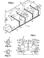
- a spray dampening system constructed in accordance with the principles of the present invention is designated broadly by the numeral 20 and is shown, as an example, as mounted on a pair of side-by-side, double width press units 22, 22 the latter of which are represented by dashed lines depicting respective end arched structures.
- a spray bar 24 is secured to each side of the units 22, 22 adjacent the aisles 25 between each pair of units 22, 22 and each of the bars 24 has eight spaced nozzle assemblies 26 for spraying dampening fluid or "water" toward an adjacent, associated dampening roller (not shown in Fig. 1).
- a dampening fluid supply cabinet 28, in cooperation with a constant volume diaphragm pump 30, comprises a supply of pressurized dampening fluid.
- a conduit means or dampening fluid supply line 34 is coupled with the cabinet 28 and the pump 30 for communicating the fluid to each of the spray bars 24.
- a filter 36 disposed downstream of the pump 30 removes contaminates in the fluid to prevent clogging of the nozzle assemblies 26 and the buildup of slime, problems particularly otherwise noticed when tap water comprises a substantial portion of the dampening fluid.
- a dampening fluid return line 38 coupled to each of the spray bars 24 enables return of dampening fluid to the supply cabinet 28.
- a Model No. 1AOD-A diaphragm pump manufactured by Marlow Pumps ITT of Midland Park, New Jersey is especially suitable for use as the pump 30 of the present invention.
- the Marlow pump has an air- actuated diaphragm that is balanced by pressurized air on one side and pressurized dampening fluid on the other side in order to extend the life of the diaphragm in comparison to mechanically actuated diaphragm pumps.
- the diaphragm pump 30 represents simplified practice in contrast to prior art dampener pumping systems comprising a pair of tanks pressurized by regulated, compressed air and having valving for discharge of dampening fluid repetitiously between alternative tanks.
- a tachometer sensor 40 such as a magnetically induced pick-up device, detects the speed of rotation of a drive shaft 42 powering the press units 22, 22.
- a wire lead 44 coupled to the sensor 40 is connected to a dampener control station 46 mounted on each of the units 22.
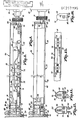
- each of the spray bars 24 includes an elongated, rectangular plate or support 48 connected on one side thereof to a housing 50.
- the spray bar 24 also includes eight elongated blocks 52 (Figs. 8 and 14) secured to the plate 48, and each of the assemblies 26 is mounted on one of the blocks 52 and is substantially enclosed by the housing 50.
- Each of the assemblies 26 includes a valve means 54 that is coupled to the supply line 34 for interruption of the flow of dampening fluid through the latter.
- the valve means 54 includes an electrically actuated solenoid coil 56 and an internal, reciprocable plunger 58 that is normally biased by a spring 60 toward a position wherein a rubber disk 62 coupled to one end of the plunger 58 is in sealing engagement with a circular valve seat 64.
- a wire lead 66 (see Fig. 1) is coupled to the solenoid coils 56 as well as the control station 46 for selective operation of the valve 54.
- the lead 66 includes a number of separate wires so that each of the eight solenoid coils 56 in each spray bar 24 can be independently controlled by a separate, infinitely variable potentiometer (not shown) that is mounted to the control station 46 for manual control during operation of the press unit 22.
- the block 52 has an internal passageway comprising a portion of the supply line 34, and each of the assemblies 26 has a chamber 68 that communicates with the supply line 34.
- Energization of the coil 56 retracts the plunger 58 against the bias presented by the spring 60 such that the disk 62 is spaced from the valve seat 64, whereupon the flow of pressurized dampening fluid is directed through a channel 70 disposed within a nozzle 72.
- each nozzle 72 has generally conical walls defining the outwardmost end of the channel 70 and an elongated slot or orifice 74 communicates the channel 70 to areas external of the nozzle 72.
- the conically configured walls enable the slot 74 to be enlarged by a suitable cutting operation so that the desired flow rate can be attained.
- a nozzle as manufactured by Spray Systems Company of Wheaton, Illinois and sold under the tradename Unijet O (tip number 11001), with an opening of 0.026", is especially suitable for practice of the instant invention.
- each of the adjacent nozzle assemblies 26 is connected to a first piping means 76 comprising a part of the conduit means or supply line 34 and interconnected by fittings 78 to the blocks 52.
- a second piping means or return line 38 of conduit means 34 is positioned within the housing 50 so that unused fluid conveyed by the supply line 34 toward the end of the spray bar 24 may be directed back toward the supply cabinet for subsequent recirculation.
- the return line 38 has a 1/8 inch outer diameter and thereby is of a dimension to provide resistance to the flow of dampening fluid back to the supply cabinet 28.
- the nozzle assembly 26 that is located on the extreme righthand end portion of the spray bar 24 (see Fig. 8) has a slightly different configuration than the remaining nozzle assemblies 26, and in Fig. 15 the first piping means 76 of the conduit means 34 is directly coupled to the second piping means or return line 38 of the conduit 34, and an enlarged bore 80 (Fig. 15) receives a fitting 82 (Figs. 8 and 13) adapted to receive the 1/8 inch O.D. tubing which comprises the remaining portion of the return line 38.
- the spray bar 24 is detachably mounted on a frame 84 of the press unit 22 by means of an outwardly extending, inverted generally U-shaped flange portion 86 of the housing 50 which is slidably engageable with a shoulder 88 of a base 90 that is fixed to the frame 84.
- the flange portion 86 which extends from a first end portion of the spray bar 24 (which represents the lefthand side of the spray bar 24 shown in Figs. 8 and 9), is formed to complementally engage five surfaces on the shoulder 88 of base 90 for purposes to be explained hereinafter.
- the mounting means which includes the flange portion 86 and a shoulder 88, also includes a knob or member 92 which detachably interconnects a second end portion of the support 48 and the press frame 84, wherein the second end portion is remote from the first end portion and is depicted on the righthand side of the spray bar 24 shown in Figs. 8 and 9.
- the member 92 is fixedly coupled to a threaded shank 94 received in a complemental bore 96 of an object 98 that is secured to an opposite side of the press frame 84 remote from the base 90.
- the member 92 is also fixed to a shaft 100 which has a cylindrical portion 102 as well as a cylindrical head 104.
- the second end portion or the righthand side of the spray bar 24 as illustrated in Figs. 8 and 9 has a plate 106 (see also Fig. 10) which is formed with a cylindrical counterbore 108 as well as a slot 110 that is generally smaller in width than the diameter of the counterbore 108.
- Rotation of the member 92 in one direction causes the shank 94 to move away from the object 98 to enable the outer shoulder of the cylindrical portion 102 of shaft 100 to become seated in the counterbore 108 (Fig. 8), whereupon further rotation of the member 92 shifts the spray bar 24 toward the base 90.
- Rotation of the member 92 in the opposite direction shifts the cylindrical portion 102 away from the counterbore 108, as illustrated in Fig. 9, and also causes the head 104 of shaft 100 to become engaged with a portion of the plate 106 opposite the counterbore 108, and subsequently continued rotation of the member 92 in the same direction moves the spray bar 24 away from the base 90.
- the return line 38 includes a first coupling body comprising a fitting 112 that is mounted on the first end portion of the spray bar 24.
- the fitting 112 is engageable with a second coupling body that is secured to the press frame 84 and which includes a shiftable valve device 114 that is received within a bore 116 of base 90.
- Fitting 118 communicates bore 116 to remaining portions of the return line 38 to enable dampening fluid to flow to the supply cabinet 28.
- the supply line 34 includes a first coupling body comprising a fitting 120 (Fig. 11) mounted on the first end portion of the spray bar 24.
- the fitting 120 is engageable with a second coupling body comprising a valve device 122 (Fig. 12) that is received within a bore of base 90 and which communicates with a fitting 124 for receiving fluid from the filter 36.
- the first end portion of the spray bar 24 also carries a male first. set of contact elements 126 that is electrically connected to a first lead means 128 which is positioned within the housing 50 and which forms a part of the lead 66.
- the base 90 supports a female second set of contact elements 130 which are electrically coupled to a second lead means 132 also forming a portion of the lead 66.
- the first lead means 128 and the second lead means 132 include a number of wires so that the control station 46 can independently actuate each of the solenoid coils 56 as may be desired.
- the spray bar 24 is positioned as shown in Fig. 8 such that the male contact elements 126 are mechanically and electrically received within the female contact elements 130.
- the fittings 112, 120 engage the shiftable valve devices 114, 122 respectively to open both of the latter and enable the flow of dampening fluid from the supply cabinet 28 to each of the nozzle assemblies 26, as well as to enable the return of dampening fluid through line 38 and back to the supply cabinet 28.
- member 92 is rotated to engage head 104 against plate 106 and thereafter shift the spray bar support 48 in a longitudinal direction toward the righthand side of Fig. 9. Simultaneously, and as shown in Fig.
- Removal of the spray bar 24 from the press unit 22 is accomplished by lifting the righthand side or second end portion of the spray bar support 48 in an upwardly direction when the spray bar 24 is in the position shown in Fig. 9.
- the bar 24 during removal pivots about the outermost and top edge of the flange portion 86, and the cylindrical head 104 simultaneously moves along slot 110 until plate 106 clears shaft 100.
- the spray bar 24 can be shifted upwardly and to the right viewing Fig. 9 until the entire flange portion 86 clears shoulder 88 of base 90, to allow the bar 24 to be completely removed from press unit 22. Installation of another bar 24 may thereupon be accomplished by reversal of these steps.
- the flange portion 86 in cooperation with shoulder 88 maintains the orientation of the spray bar 24 in a predetermined position relative to the orientation of base 90, so that during installation of the bar 24 the fittings 112, 120 as well as the male contact elements 126 can be readily and accurately received by valve devices 114, 122 and the female contact elements 130 correspondingly.
- removal and installation of the spray bar 24 can be accomplished during operation of the press unit 22, since the shiftable valve devices 114, 122 immediately shut off that portion of the flow of dampening fluid which would normally be directed to the same spray bar, so that leakage of the fluid is substantially precluded.
- a continuous web of newspaper 134 is directed upwardly toward the nip between an adjacent pair of side-by-side blanket of rollers 136, 136 which are each in rolling surface contact with a respective plate cylinder 138, 138.
- a conventional lithographic plate is mounted on the surface of each of the plate cylinders 138 and has at least one ink receptive area corresponding to image areas of the printed image, as well as other areas that are not receptive to ink.
- Each of two ink trains has a series of rollers for transferring a film of ink to one of the plate cylinders 138.
- the dampening system 20 Spaced from the ink train 140 on each side of the press 22 is the dampening system 20, which includes a first roller 142, a second roller 144 (that is optionally longitudinally oscillable) and a third roller 146.
- the longitudinal axis of the spray bar 24 is parallel and substantially horizontally aligned with the longitudinal axis of the third roller 146, so that the nozzles 72 provide an elongated, overlapping pattern of spray along the length of the third roller 146, as shown in Fig. 3.
- rollers 142, 144 and 146 are parallel with the rotational axis of plate cylinder 138.
- a water pan 148 (Fig. 2) piped to a drain system catches any accidental leakage or drippage which might occur, for example, during startup of the dampening system 20.
- the first roller 142 is in rolling surface engagement with the plate cylinder 138 and has a flexible, synthetic rubber surface having a depth of 1/2 inch with a Shore A durometer hardness of 25 to 40.
- the second roller 144 is in rolling contact with the first roller 142 and has a hydrophilic outer surface which is selected from the group consisting of chromium, nickel and ebonite, and the surface of roller 144 has a Shore A durometer hardness of 99.
- the third roller 146 in turn, is in rolling engagement with the second roller 144 and has a flexible, synthetic rubber surface with a depth of 1/2 inch and with a Shore A durometer hardness of 25 to 40, similar to the first roller 142.
- Both of the rubber rollers 142, 146 are provided with a matted surface finish, which facilitates dispersion of the dampening fluid throughout the entire surface area of the rollers 142, 146 and which also tends to reduce slippage between the rollers since the latter are surface driven from the plate cylinder 138.
- a 120 grit, sandpaper type material comprised of silicon carbide particles provides a superior finish when the sandpaper material is applied at 70 to 80 pounds of pressure against the rollers 142, 146 while the latter are rotated at approximately 1,200 rpm.
- the sandpaper is applied against the surface of the rollers 142, 146 in a dry fashion until the surface of the same has a uniform, matt finish, and subsequently the surface of the rollers 142, 146 is slightly buffed. It has been found that use of the 120 grit silicon carbide sandpaper provides a superior surface finish for the purposes of the dampening system disclosed herein in comparison to a finish which is sometimes provided by applying a 180 grit sandpaper material against a rubber surfaced roller.
- Figs. 6 and 7 show another use of the spray dampening system 20a of the present invention as installed on a press unit 22a having a blanket cylinder 136a and a plate cylinder 138a in rolling contact with the blanket cylinder 136a.
- the press 22a in Figs. 6 and 7 has an ink train 140a that is separate from and spaced from the dampening system 20a.
- a first roller 142a is in surface contact with plate cylinder 138a, a second roller 144a is in rolling engagement with the first roller 142a, and a third roller 146a is in rolling contact with the second roller 144a.
- a spray bar 24a of the dampening system 20a is positioned so that a spray of dampening fluid is directed upwardly toward the third roller 146a as shown in Fig. 6.
- Water pan 148a is connected to a drain to dispose of accidental leakage or excess dampening fluid when desired.
- the rollers 142a-146a are identical to the rollers 142-146 shown in Fig. 2, both in material composition as well as the uniform, matt finish that is provided for the rubber surface.
- dampening fluid is metered through a first nip.between the first roller 142 and the second roller 144, and is also metered through a second nip between the second roller 144 and the third roller 146, and moreover the dampening fluid is metered through another nip between the first roller 142 and the plate cylinder 138 so that even, uniform distribution of dampening fluid is enhanced over the surface areas of the plate cylinder 138.
- An outer edge segment 149a (Fig. 7) is advantageously provided on roller 146a with a roughened or knurled finish which is rougher in texture than the remaining major portion of roller 146a to facilitate frictional engagement for surface driving of roller 146 from plate cylinder 138a.
- roller 142a as well as rollers 142, 146 in Fig. 2 are desirably also provided with similar edge segments.
- the sensor 40 (Fig. 1) detects the speed of the drive shaft 42 and transmits a signal to the control station 46, and the latter then transmits a series of electrical pulses to the coils 56 wherein the frequency of the pulses is determined by the speed of the drive shaft 42.
- the duration of each pulse is normally held constant, the potentiometer associated with the control station 46 allows independent manual adjustment of the duration of the pulses for each nozzle assembly 26, may be desired when relatively fine control of the quantity of water reaching the plate is needed.
- Each potentiometer is infinitely variable and is operable to change the duration of the pulse in linear relation to the angular degree of rotation of the potentiometer shaft.
- the potentiometer is used rarely if at all, and instead the operator is encouraged to retain the rotative position of the potentiometer in a fixed orientation and generally not adjust the same unless abnormal conditions appear to be present.
- Fig. 3 represents the preferred coverage of the system 20 of the instant invention as applied to newspapers commonly found in the United States, although it should be understood that such an illustration is representative only of the coverage and does not imply that the dampening fluid is sprayed directly onto a roller in engagement with paper.
- a spray bar 24 is shown having eight equally spaced nozzles 72 which direct the dampening fluid over a double width of newspaper 134 having a dimension typically of 55" and representing four pages.
- a representative depiction of the pattern defined by the nozzles 72 is illustrated in broken lines, and the configuration of the spray pattern on the associated third roller 146 (not shown in Figs. 4-5) is highly critical to the success of the present invention.
- the aforementioned preferred nozzle, No. 11001, sold under the tradename Unijet @ by Spray Systems Company of Wheaton, Illinois provides a spray angle 0 which is indicated at the numeral 150 in Fig. 4 and which is 110° at 40 psi. It is preferred that the pressure of the dampening fluid as provided by the pump 30 remain at approximately 40 psi, since smaller pressures will reduce the angle 9 accordingly while larger pressures will increase the spray angle 0.
- a pressure of 40 psi is considerably advantageous over conventional spray systems using pressures as high as 80 psi or 100 psi, since higher pressures cause system components to experience greater wear and leakage, and increase the operational costs of the press.
- the center-to-center distance between the center of the orifices 74 of the nozzles 72 is 4 inches to 10 inches, although better results have been observed when the center-to-center spacing is 6 to 8 inches, and best results have been observed when the center-to-center spacing is 7.1 inch.
- the spray pattern that is produced on the third roller 146 is critically defined by the distance between the nozzles 72 and the third roller 146 as well as the aforementioned distance between adjacent nozzles 72. Good results have been observed when the nozzle 72 is spaced from the third roller 146 a distance in the range of 2.5 inches to 3.2 inches (represented as “X1" and “X2" respectively in Fig. 4), and best results have been observed when the nozzle 72 is spaced from the third roller 146 a distance of 2.8 inches (designated "X” in Fig. 4). Again referring to Fig.
- the spray pattern produced from the nozzles 72 when the spray reaches the third roller 146 has an elongated configuration with tapered edge portion, and the thickness of the spray pattern along the majority of the length of the latter is typically 1.25 inch to 1.50 inch.
- the spray produced by the nozzles 24 is uniformly distributed in the entire area of the pattern, although the edges of the latter are somewhat indistinct. Overspray at locations corresponding to areas adjacent edges of the plate is carefully maintained so that the plate edges are properly dampened.
- each of the spray patterns shown in Fig. 5 represent a smaller quantity of dampening fluid per longitudinal inch of roller 146 from each nozzle 72 that is produced within the center regions of the spray pattern.
- the nozzles 72 are arranged so that the spray patterns from adjacent nozzles 72 overlap, sufficient amounts of dampening fluid are provided on the third roller 146 in all regions along the length of the latter.
- the parameters set forth hereinabove which detail preferred center-to-center nozzle spacings as well as the spacing between the nozzles 72 and the third roller 146 enable the dampening fluid to be uniformly and evenly distributed along the length of the third roller 146 to a degree heretofore unknown, even though some overlap is present.
- the overlap of spray pattern is highly critical, since excess dampening fluid at these locations can otherwise cause water spotting at corresponding locations of the printed image.
- An important aspect of the present invention is the elimination of stagnant areas in the dampening fluid conduit means so that the fluid is constantly in circulation for filtering and distribution to nozzles 72.
- the lines 34, 38, the nozzle assemblies 26 as well as the supply cabinet 28 have been constructed without stagnant or "dead" areas, and the filter 32 continuously removes contaminates during each pass of the fluid.
- known prior art dampening systems utilize a screen filter associated with each spray nozzle in an attempt to avoid clogging of the nozzle orifices.
- the volume of dampening fluid to be delivered to the plate cylinder during each rotation thereof should range from 30% to 50% on an established scale wherein 0% is confirmed by light scumming and 100% is confirmed by excessive dampening fluid in the press 22.
- An oversupply of dampening fluid can be observed by water retained in the nips of the rollers, a shiny reflection of water on the plate, or water standing in the ink fountain.
- An oversupply of dampening fluid may also be observed by excessive emulsification of the ink such that black ink becomes gray and the resultant printed image is not of high contrast.
- the instant invention may also be practiced by construction of a press 22 in accordance with a second set of parameters in combination with the aforementioned nozzle locations which yield high quality printing but of somewhat lesser quality than the printing obtained by the first set described above.
- the duration of each pulse is in a range of approximately 20 milliseconds to approximately 40 milliseconds
- the pressure of the dampening fluid as provided by the pump 30 is in the range of approximately 30 psig to approximately 50 psig.
- the series of pulses has a frequency ranging from approximately 100 pulses per minute to approximately 400 pulses per minute.
- a third set of parameters in combination with the abovementioned nozzle locations has also been found to provide good results, although of somewhat lesser quality than the result obtained through use of the parameters described in the first and second sets.
- the duration of each pulse lies in a range from approximately 5 milliseconds to approximately 75 milliseconds, and the pump 30 provides pressure on the dampening fluid of approximately 20 psig to approximately 60 psig.
- the frequency of the pulse series is in a range of approximately 50 pulses per minute to approximately 600 pulses per minute at full press speed.
- the uniform, fine spray provided by practice of the instant invention provides a printed image of substantially high quality, due not only to the nature of the surface driven rollers 142, 144 and 146 and the nips therebetween, but also due to the abovementioned critical parameters, and particularly the nozzle center-to-center spacings and nozzle-to-roller spacings, and the duration and frequency of each pulse of sprayed dampening fluid. Additionally, by providing a dampening system which is separate from and not associated with any components of the ink train, excessive intermixing of the dampening fluid in the ink is substantially precluded.
- the spray bar 24 to be mounted within the aisle 25 of adjacent press units 22, enabling easy access to the spray bars 24 as may be necessary.
- the detachable means mounting the spray bars 24 to the press frame 84 allows any of the bars 24 to be selectively removed from the press unit 22 during operation of the latter, so that elaborate shutdown procedures can be avoided.
- plugging of the latter is avoided to ensure that the third roller 146 inevitably receives a uniform, fine distribution of dampening fluid along the length of the latter for subsequent transfer to the plate cylinder 138.
Landscapes
- Engineering & Computer Science (AREA)
- Mechanical Engineering (AREA)
- Rotary Presses (AREA)
- Inking, Control Or Cleaning Of Printing Machines (AREA)
Applications Claiming Priority (2)
| Application Number | Priority Date | Filing Date | Title |
|---|---|---|---|
| US06/876,929 US4708058A (en) | 1985-10-10 | 1986-06-20 | Water pulse spray dampening system and method for printing presses |
| US876929 | 1997-06-16 |
Publications (2)
| Publication Number | Publication Date |
|---|---|
| EP0257195A2 true EP0257195A2 (de) | 1988-03-02 |
| EP0257195A3 EP0257195A3 (de) | 1989-05-10 |
Family
ID=25368860
Family Applications (1)
| Application Number | Title | Priority Date | Filing Date |
|---|---|---|---|
| EP87106758A Ceased EP0257195A3 (de) | 1986-06-20 | 1987-05-09 | System und Verfahren zum Befeuchten mittels pulsiertem Sprühen von Wasser für Druckmaschinen |
Country Status (3)
| Country | Link |
|---|---|
| US (1) | US4708058A (de) |
| EP (1) | EP0257195A3 (de) |
| JP (1) | JPS6372549A (de) |
Cited By (2)
| Publication number | Priority date | Publication date | Assignee | Title |
|---|---|---|---|---|
| WO2000032397A1 (en) * | 1998-12-02 | 2000-06-08 | Baldwin Jimek Ab | A method and device at a spraying ramp for a printing press |
| EP1635221A1 (de) * | 2004-09-13 | 2006-03-15 | Fuji Photo Film Co., Ltd. | Verfahren und Apparat zur Einstellung der Feuchtigkeit eines Objekts |
Families Citing this family (26)
| Publication number | Priority date | Publication date | Assignee | Title |
|---|---|---|---|---|
| US5038681A (en) * | 1988-01-19 | 1991-08-13 | Jimek International Ab | Control method and apparatus for spray dampener |
| CA1313388C (en) | 1988-01-19 | 1993-02-02 | Jimek A.B. | Spray dampener valve assembly and control system |
| US4901640A (en) * | 1988-10-19 | 1990-02-20 | Rockwell International Corporation | Oscillating form roller dampener |
| US4932319A (en) * | 1988-10-26 | 1990-06-12 | Ryco Graphic Manufacturing, Inc. | Spray dampening system for offset press |
| US5207168A (en) * | 1989-11-13 | 1993-05-04 | The Toro Company | Method and apparatus for treating turf |
| US5119744A (en) * | 1989-11-13 | 1992-06-09 | The Toro Company | Method and apparatus for treating turf |
| JPH059932U (ja) * | 1991-07-23 | 1993-02-09 | サカタインクス株式会社 | 湿し水供給装置 |
| US5540390A (en) * | 1994-09-19 | 1996-07-30 | Rockwell International Corporation | Spray bar assembly for a printing press |
| JP2689309B2 (ja) * | 1994-09-30 | 1997-12-10 | 株式会社東京機械製作所 | 平版印刷機のダンプニング装置 |
| US5605105A (en) * | 1994-10-17 | 1997-02-25 | Great Plains Manufacturing, Incorporated | Method and apparatus for placing dry or liquid materials into the soil subsurface without tillage tools |
| JP2746855B2 (ja) * | 1995-04-03 | 1998-05-06 | 株式会社東京機械製作所 | ノズル式ダンプニング装置における異常検出装置 |
| DE19645799A1 (de) * | 1996-11-07 | 1998-05-20 | Roland Man Druckmasch | Papierbahnfangvorrichtung |
| US5974965A (en) * | 1997-02-03 | 1999-11-02 | Baldwin Graphic Syetems, Inc. | Single point quick disconnect spray bar |
| US6327974B1 (en) | 1999-03-01 | 2001-12-11 | Heidelberger Druckmaschinen Ag | Spray dampening device having high effective spray frequency and method of using |
| JP2002361825A (ja) * | 2001-06-08 | 2002-12-18 | Mitsubishi Heavy Ind Ltd | 湿し装置 |
| DE10258325B4 (de) * | 2002-10-25 | 2005-08-18 | Koenig & Bauer Ag | Verfahren zur Einstellung eines Sprühfeuchtwerks |
| SE525124C2 (sv) * | 2003-06-30 | 2004-12-07 | Baldwin Jimek Ab | Spraymunstycke |
| US7117788B2 (en) * | 2004-02-27 | 2006-10-10 | Goss International Americas, Inc. | Spray device |
| WO2006072557A1 (de) * | 2005-01-05 | 2006-07-13 | Koenig & Bauer Aktiengesellschaft | Druckeinheit einer druckmaschine mit mindestens einem farbwerk und mindestens einem feuchtwerk |
| FI118420B (fi) * | 2006-03-21 | 2007-11-15 | Veslatec Oy | Suihkuttava kostutusjärjestelmä painokoneissa |
| US20080229945A1 (en) * | 2007-03-24 | 2008-09-25 | Niemiro Michael A | Spray dampening valve having associated electronic adjustment and correction data |
| DE102007015401B4 (de) * | 2007-03-30 | 2010-09-23 | Koenig & Bauer Aktiengesellschaft | Feuchtwerk für ein Druckwerk einer Druckmaschine |
| DE102008017275B4 (de) * | 2008-04-04 | 2010-11-11 | Technotrans Ag | Befeuchtungsvorrichtung eines Sprühfeuchtwerks |
| SE535299C2 (sv) * | 2010-10-15 | 2012-06-19 | Generic Technology I Kivik Ab | Monteringsplatta för sprayenheter och dess användning i en tryckpress |
| US9821615B2 (en) * | 2013-06-07 | 2017-11-21 | Android Industries Llc | System and method for applying a lubricating paste to a wheel |
| SE543357C2 (en) * | 2018-06-29 | 2020-12-15 | Baldwin Jimek Ab | Service tracking system for spray bars and the like |
Family Cites Families (14)
| Publication number | Priority date | Publication date | Assignee | Title |
|---|---|---|---|---|
| US2347619A (en) * | 1942-04-21 | 1944-04-25 | Goss Printing Press Co Ltd | Rotary inking mechanism and process |
| US2408449A (en) * | 1943-09-13 | 1946-10-01 | Pacific Can Company | Fluid fountain for printing presses |
| US2448226A (en) * | 1944-02-04 | 1948-08-31 | Marsden Horace Edwin | Moistening device for offset presses |
| US3455238A (en) * | 1965-10-22 | 1969-07-15 | Web Offset Publications Corp | Water dampening system with soft driven wheels and hard drive wheels |
| DE1611313B1 (de) * | 1967-11-20 | 1970-12-23 | Lau Wolf | Feuchtwerk fuer eine Offsetdruckmaschine |
| US3651756A (en) * | 1969-08-11 | 1972-03-28 | Roy R Smith Jr | Spray dampening system with individual metering pumps for offset press |
| DE2058667B1 (de) * | 1970-11-28 | 1972-05-25 | Weitmann & Konrad | Vorrichtung in Druckereimaschinen,insbesondere Offsetmaschinen,zum Aufbringen von Fluessigkeit auf bewegte Flaechen |
| DE2157778C2 (de) * | 1971-11-22 | 1973-10-25 | Heidelberger Druckmaschinen Ag, 6900 Heidelberg | Einrichtung in Offsetdruckmaschinen zur Regelung der Feuchtflussigkeitszu fuhr an Feuchtwerken |
| DE2221289C2 (de) * | 1972-04-29 | 1974-01-17 | Maschinenfabrik Augsburg-Nuernberg Ag, 8900 Augsburg | Von einem Farbwerk getrennt angeordnetes Feuchtwerk für Rotationsoffsetdruckmaschinen |
| JPS4929241A (de) * | 1972-07-18 | 1974-03-15 | ||
| US3939668A (en) * | 1974-11-21 | 1976-02-24 | Morris Herman H | Balanced liquid level head pressure control systems |
| US4064801A (en) * | 1975-08-12 | 1977-12-27 | Ryco Graphic Manufacturing, Inc. | Spray dampening system for offset printing |
| FR2478958A1 (fr) * | 1980-04-01 | 1981-10-02 | Decoufle | Dispositif d'alimentation en encre des appareils d'imprimerie pour machines a confectionner les cigarettes |
| US4469024A (en) * | 1982-10-18 | 1984-09-04 | Press Machinery Corporation | Fluid dispensing apparatus such as spray dampener for printing press and method of dispensing |
-
1986
- 1986-06-20 US US06/876,929 patent/US4708058A/en not_active Expired - Lifetime
-
1987
- 1987-05-09 EP EP87106758A patent/EP0257195A3/de not_active Ceased
- 1987-06-20 JP JP62154256A patent/JPS6372549A/ja active Pending
Cited By (3)
| Publication number | Priority date | Publication date | Assignee | Title |
|---|---|---|---|---|
| WO2000032397A1 (en) * | 1998-12-02 | 2000-06-08 | Baldwin Jimek Ab | A method and device at a spraying ramp for a printing press |
| AU751026B2 (en) * | 1998-12-02 | 2002-08-08 | Baldwin Jimek Ab | A method and device at a spraying ramp for a printing press |
| EP1635221A1 (de) * | 2004-09-13 | 2006-03-15 | Fuji Photo Film Co., Ltd. | Verfahren und Apparat zur Einstellung der Feuchtigkeit eines Objekts |
Also Published As
| Publication number | Publication date |
|---|---|
| EP0257195A3 (de) | 1989-05-10 |
| US4708058A (en) | 1987-11-24 |
| JPS6372549A (ja) | 1988-04-02 |
Similar Documents
| Publication | Publication Date | Title |
|---|---|---|
| US4708058A (en) | Water pulse spray dampening system and method for printing presses | |
| US4455938A (en) | Dampening apparatus for lithographic press | |
| US4690055A (en) | Keyless inking system for offset lithographic printing press | |
| EP0382347A2 (de) | Druckapparat mit einem doppelten Farbsystem | |
| EP0461426B1 (de) | System zum Zuführen von Druckflüssigkeit unter Druck zum lithographischen Drucken ohne Farbmesser | |
| EP0517462B1 (de) | Zuführungssystem für Anfeuchtflüssigkeit | |
| US5740739A (en) | Method and device for washing a form cylinder and an associated applicator roller in a printing machine | |
| US4619198A (en) | Method and apparatus for keyless offset printing | |
| JPS60127155A (ja) | 平版印刷機における給湿装置及び給湿方法 | |
| US6571710B1 (en) | Keyless inker for a printing press | |
| US5315930A (en) | Keyless inking system for a printing press | |
| EP1441908B1 (de) | Druckmaschinenwalzen-reinigungsverfahren und -vorrichtung | |
| US5440982A (en) | Inking system for a printing press | |
| US4289167A (en) | Non-drip fluid delivery system | |
| US5878663A (en) | Dampener recirculator apparatus for a printing press | |
| JPH05330009A (ja) | オフセット印刷機の湿し水供給装置 | |
| US4535692A (en) | Apparatus for supplying liquid mediums to rollers of printing machines utilizing a distributor plate | |
| EP1389523B1 (de) | Druck- oder Beschichtungsmachine | |
| US20080257180A1 (en) | Dampening Control for a Printing Press | |
| GB2073666A (en) | Printing press dampener system | |
| EP0525586A1 (de) | Farbzuführvorrichtung für eine Druckmaschine | |
| US5694846A (en) | Fountain solution supply system | |
| JPH059932U (ja) | 湿し水供給装置 | |
| CN220390722U (zh) | 一种水性油墨印刷装置 | |
| EP1003638A1 (de) | Verfahren und einrichtung zur farbzufuhr |
Legal Events
| Date | Code | Title | Description |
|---|---|---|---|
| PUAI | Public reference made under article 153(3) epc to a published international application that has entered the european phase |
Free format text: ORIGINAL CODE: 0009012 |
|
| AK | Designated contracting states |
Kind code of ref document: A2 Designated state(s): AT BE CH DE ES FR GB GR IT LI LU NL SE |
|
| PUAL | Search report despatched |
Free format text: ORIGINAL CODE: 0009013 |
|
| AK | Designated contracting states |
Kind code of ref document: A3 Designated state(s): AT BE CH DE ES FR GB GR IT LI LU NL SE |
|
| 17P | Request for examination filed |
Effective date: 19891102 |
|
| 17Q | First examination report despatched |
Effective date: 19910328 |
|
| STAA | Information on the status of an ep patent application or granted ep patent |
Free format text: STATUS: THE APPLICATION HAS BEEN REFUSED |
|
| 18R | Application refused |
Effective date: 19930501 |
|
| RIN1 | Information on inventor provided before grant (corrected) |
Inventor name: SMITH, GARY R. |