EP0257196A2 - Zweipoliger Rotor eines Schrittmotors mit Ritzelantrieb und Herstellungsverfahren - Google Patents
Zweipoliger Rotor eines Schrittmotors mit Ritzelantrieb und Herstellungsverfahren Download PDFInfo
- Publication number
- EP0257196A2 EP0257196A2 EP87106785A EP87106785A EP0257196A2 EP 0257196 A2 EP0257196 A2 EP 0257196A2 EP 87106785 A EP87106785 A EP 87106785A EP 87106785 A EP87106785 A EP 87106785A EP 0257196 A2 EP0257196 A2 EP 0257196A2
- Authority
- EP
- European Patent Office
- Prior art keywords
- rotor
- magnet member
- stepping motor
- rotor body
- axis
- Prior art date
- Legal status (The legal status is an assumption and is not a legal conclusion. Google has not performed a legal analysis and makes no representation as to the accuracy of the status listed.)
- Withdrawn
Links
Images


Classifications
-
- G—PHYSICS
- G04—HOROLOGY
- G04C—ELECTROMECHANICAL CLOCKS OR WATCHES
- G04C15/00—Clocks driven by synchronous motors
-
- G—PHYSICS
- G04—HOROLOGY
- G04C—ELECTROMECHANICAL CLOCKS OR WATCHES
- G04C13/00—Driving mechanisms for clocks by primary clocks
- G04C13/08—Secondary clocks actuated intermittently
- G04C13/10—Secondary clocks actuated intermittently by electromechanical step-advancing mechanisms
- G04C13/11—Secondary clocks actuated intermittently by electromechanical step-advancing mechanisms with rotating armature
-
- H—ELECTRICITY
- H02—GENERATION; CONVERSION OR DISTRIBUTION OF ELECTRIC POWER
- H02K—DYNAMO-ELECTRIC MACHINES
- H02K1/00—Details of the magnetic circuit
- H02K1/06—Details of the magnetic circuit characterised by the shape, form or construction
- H02K1/22—Rotating parts of the magnetic circuit
- H02K1/27—Rotor cores with permanent magnets
- H02K1/2706—Inner rotors
- H02K1/272—Inner rotors the magnetisation axis of the magnets being perpendicular to the rotor axis
- H02K1/2726—Inner rotors the magnetisation axis of the magnets being perpendicular to the rotor axis the rotor consisting of a single magnet or two or more axially juxtaposed single magnets
-
- H—ELECTRICITY
- H02—GENERATION; CONVERSION OR DISTRIBUTION OF ELECTRIC POWER
- H02K—DYNAMO-ELECTRIC MACHINES
- H02K37/00—Motors with rotor rotating step by step and without interrupter or commutator driven by the rotor, e.g. stepping motors
- H02K37/10—Motors with rotor rotating step by step and without interrupter or commutator driven by the rotor, e.g. stepping motors of permanent magnet type
- H02K37/12—Motors with rotor rotating step by step and without interrupter or commutator driven by the rotor, e.g. stepping motors of permanent magnet type with stationary armatures and rotating magnets
- H02K37/14—Motors with rotor rotating step by step and without interrupter or commutator driven by the rotor, e.g. stepping motors of permanent magnet type with stationary armatures and rotating magnets with magnets rotating within the armatures
- H02K37/16—Motors with rotor rotating step by step and without interrupter or commutator driven by the rotor, e.g. stepping motors of permanent magnet type with stationary armatures and rotating magnets with magnets rotating within the armatures having horseshoe armature cores
-
- H—ELECTRICITY
- H02—GENERATION; CONVERSION OR DISTRIBUTION OF ELECTRIC POWER
- H02K—DYNAMO-ELECTRIC MACHINES
- H02K7/00—Arrangements for handling mechanical energy structurally associated with dynamo-electric machines, e.g. structural association with mechanical driving motors or auxiliary dynamo-electric machines
- H02K7/10—Structural association with clutches, brakes, gears, pulleys or mechanical starters
- H02K7/116—Structural association with clutches, brakes, gears, pulleys or mechanical starters with gears
Definitions
- This invention relates generally to wristwatch movements incorporating stepping motors of the Lavet type, which drive the hands of the wristwatch through a gear train.
- the motor is of the type which receives periodic stepping pulses from a quartz-synchronized integrated circuit. More particularly, the invention relates to the assembly method of manufacture of the bipolar permanent magnet rotor member with drive pinion for the stepping motor.
- Wristwatch movements which drive a center wheel directly connected to the minute hand by means of a stepping motor rotor acting at the periphery of a wheel connected to the minute hand shaft.
- a single reduction gear member can perform the proper reduction to drive an hour hand shaft coaxial with the minute hand shaft.
- a timepiece stepping motor of the Lavet-type includes a rotor with a pair of driving pins stepping the rotor 180 degrees once each minute.
- the pins drive a toothed wheel directly at its periphery which is also connected to the minute hand, so as to step the minute hand once each minute.
- Constructions are known in which a bipolar permanent magnet serving as the rotor in a two-piece stator of a Lavet stepping motor includes an integral toothed driving pinion, which cooperates with a toothed center wheel for a timepiece.
- the arresting mechanism for holding the rotor magnet at rest position with respect to the stator between steps is formed by interaction between the ends of the stator poles and the polarity of the permanent magnet rotor.
- the permanent magnet is round, it is difficult to accurately determine the axis of magnetization which causes the magnet to cooperate with the stator to determine its rest or stable position. This makes it very difficult to provide the proper offset angle between the axis of magnetization and the axis passing through the driving pinion teeth as they make engagement with the toothed wheel.
- one object of the present invention is to provide an improved bipolar stepping motor rotor with drive pinion which properly orients the pinion with respect to the bipolar permanent magnet.
- Another object of the invention is to provide an improved method of manufacture of a bipolar stepping motor rotor with drive pinion.
- Still another object of the invention is to provide an improved stepping motor rotor for a Lavet stepping motor directly driving a center wheel.
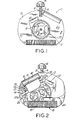
- the wristwatch movement shown generally as 1 includes a nonmagnetic frame member, 2 preferably of plastic material, such as polycarbonate which may be precisely molded to define the various recesses and journals serving as bearings for the gear members, as well as being locally deformable upon application of heat to secure components to the frame plate.
- a stem 3 is manually actuatable by crown 4 with respect to a detent spring 5 to actuate electrical switch plate contacts, such as 6, to control the operation and setting of the wristwatch.
- a stepping motor rotor having two drive pins cooperating with 60 external teeth on a center wheel 8 is periodically stepped or rotated 180 degrees once per minute.
- the driving pulses are provided by a drive circuit assembly shown generally as 9, comprising a quartz crystal 10, and an integrated circuit (not ' shown) encapsulated within a monolithic plastic housing 11.
- the integrated circuit is connected to a lead frame having. various conductive extensions such as battery terminals 12 and 13, quartz crystal attachment leads 14, 15 and coil connection leads 16, 17.
- the stepping motor shown generally as 18 comprises a coil 19 with leads connected to terminal 16, 17 of the drive circuit assembly.
- a first stator member 20 has a first pole shoe 20a and a second stator member 21 has a second pole shoe 21a.
- the pole shoes are positioned on either side of and abut a cylindrical wall member 22 of nonmagnetic material which is preferably integral with the frame plate 2.
- the wall member 22 holds a cap 23 of nonmagnetic material such as brass with a journal 23a for one end of the stepping motor rotor.
- the first and second stator members 20, 21 are disposed in a recess defined in the frame plate which locates them in place.
- the frame plate is deformed by heat during assembly at locations such as 24, 25 and 26 to hold the stator members 20, 21 in place as well as to force them abut the cylindrical wall 22.
- the frame plate 2 has fixed therein a metal center post 27 which internally journals an hour wheel shaft 28 with an hour wheel 29 fixed to its lower end.
- Shaft 28 is adapted to receive the hour hand 30 fixed to its upper end above a dial 42.
- the center post also serves to externally journal a center wheel pinion member 31 which is attached to center wheel 8 and adapted to receive a minute hand 32 on its upper end.
- Speed reduction between the minute hand and hour hand is provided by a reduction gear and pinion member 33 which is journaled in frame plate 2, and held in place by a metal cap 34.
- the stepping motor rotor, indicated by reference 35 is journaled at one end in a hole 36 molded in the frame plate 2 coaxial with wall 22, and journaled at its other end in the aforementioned hole 23a in the cap member 23.
- the first stator member 20 includes a stator portion 20b extending outside of the coil and terminating in an offset portion 20c at one end of coil 19.
- the second stator member 21 has connected to its pole shoe 21a an extending longitudinal core member 21b which passes through an opening 19a in the center of the coil. Core member 21b extends beyond the coil to terminate in a portion 21c overlapping stator portion 20c so as to be in magnetic circuit therewith.
- the pole shoes 20a and 21a define arcuate pole faces 20d and 21d respectively.
- the pole faces in turn, define opposed recess notches 20e, 2le respectively which serve to determine the rest position of rotor 35 in a manner known in the art.
- Rotor 35 comprises a permanent magnet portion 35a with a plastic overmolding portion 35b.
- the axis of rotor 35 is accurately positioned with respect to cylindrical wall 22 by means of journal hole 36 molded in frame plate 2 and journal 23a in the cap 23 (see Fig. 3).
- the pole shoe faces 20d, 21d are, in turn, accurately located with respect to the cylindrical wall 22, by abutting its outer surface.
- the rotor 35' comprises a permanent magnet member 35a with a central part and a pair of magnetic north and south poles on opposite ends.
- the pole ends are arcuate as shown, although they could also be flat.
- the magnet member 35a has an axis of magnetization passing through the poles which is best seen in Fig. 6 of the drawing designated by line m-m which is symmetrical with respect to the axis of the magnet.
- a plastic rotor body 35b is overmolded around the magnet at the time of production so as to completely surround the central part of the magnet member 35a.
- the rotor 35b includes an integral drive pinion portion for interacting with the toothed center wheel 8 (Fig. 6).
- the drive pinion portion comprises a pair of parallel drive pins 35c.
- the opposed ends of the rotor body are arcuate as shown, although they could also be flat.
- a line through both of the pins 35c is arbitrarily defined as an axis of engagement (p-p).
- An angle A is formed between the axis of magnetization and the axis of engagement which may be preselected as ideal for any particular design.
- Axis p-p is unlikely to lie along the axis of symmetry of the rotor body, which surrounds the central part of magnet 35a.
- the axes p-p and m-m may be fixed at a preselected angle with respect to one another at the moment of manufacture by virtue of the manufacturing process which forms the plastic material of the rotor around the central part of the magnet.
- plastic material such as polyimide 12 or equivalent are suitable for molding around a magnet member at the time of manufacture.
- the molding which includes the driving pins 35c also provides bearing journals, such as 35d above and below the magnet which mount the rotor in bearing holes, such as 23a, 36 for rotation.
- the magnet may be provided from several commercially available materials, such as samarium cobalt 5.
- the method of manufacture consists of use of a cavity injection molding process.
- the cavity of the mold provides properly shaped cavities for the journal bearing surfaces on the rotor, and the two drive pins properly oriented at angle A.
- the permanent magnet is placed in the mold, and plastic material is injected around its central part and into the pin cavities. When the rotor is removed, the plastic material firmly secures the magnet at the proper orientation with respect to the drive pins.
Landscapes
- Engineering & Computer Science (AREA)
- Power Engineering (AREA)
- Physics & Mathematics (AREA)
- General Physics & Mathematics (AREA)
- Electromechanical Clocks (AREA)
- Connection Of Motors, Electrical Generators, Mechanical Devices, And The Like (AREA)
Applications Claiming Priority (2)
| Application Number | Priority Date | Filing Date | Title |
|---|---|---|---|
| US06/899,271 US4700091A (en) | 1986-08-22 | 1986-08-22 | Bipolar stepping motor rotor with drive pinion and method of manufacture |
| US899271 | 1986-08-22 |
Publications (2)
| Publication Number | Publication Date |
|---|---|
| EP0257196A2 true EP0257196A2 (de) | 1988-03-02 |
| EP0257196A3 EP0257196A3 (de) | 1988-12-07 |
Family
ID=25410704
Family Applications (1)
| Application Number | Title | Priority Date | Filing Date |
|---|---|---|---|
| EP87106785A Withdrawn EP0257196A3 (de) | 1986-08-22 | 1987-05-11 | Zweipoliger Rotor eines Schrittmotors mit Ritzelantrieb und Herstellungsverfahren |
Country Status (9)
| Country | Link |
|---|---|
| US (1) | US4700091A (de) |
| EP (1) | EP0257196A3 (de) |
| JP (1) | JPS6356165A (de) |
| KR (1) | KR880003226A (de) |
| CN (1) | CN87105648A (de) |
| CA (1) | CA1274268A (de) |
| IN (1) | IN169437B (de) |
| MX (1) | MX160122A (de) |
| PT (1) | PT85222A (de) |
Families Citing this family (50)
| Publication number | Priority date | Publication date | Assignee | Title |
|---|---|---|---|---|
| US5065063A (en) * | 1988-03-30 | 1991-11-12 | Aisin Seiki Kabushiki Kaisha | Rotating apparatus |
| JPH0723982U (ja) * | 1993-09-27 | 1995-05-02 | 原町精器株式会社 | ステッピングモータ |
| US6274939B1 (en) | 1998-09-11 | 2001-08-14 | American Electronic Components | Resin ceramic compositions having magnetic properties |
| JP2002354777A (ja) * | 2001-03-23 | 2002-12-06 | Tdk Corp | ステッピングモータ |
| US6663827B2 (en) | 2001-04-13 | 2003-12-16 | Romain L. Billiet | Rare earth magnet rotors for watch movements and method of fabrication thereof |
| US20030183954A1 (en) * | 2002-03-15 | 2003-10-02 | Wolf Ronald J. | Magnetic resin composition and method of processing |
| US7955357B2 (en) | 2004-07-02 | 2011-06-07 | Ellipse Technologies, Inc. | Expandable rod system to treat scoliosis and method of using the same |
| JP4458988B2 (ja) * | 2004-08-31 | 2010-04-28 | 日本精機株式会社 | マグネットロータおよびそのマグネットロータを備えた可動磁石式計器、そのマグネットロータを備えたステッピングモータ |
| US7862502B2 (en) | 2006-10-20 | 2011-01-04 | Ellipse Technologies, Inc. | Method and apparatus for adjusting a gastrointestinal restriction device |
| US20090112263A1 (en) | 2007-10-30 | 2009-04-30 | Scott Pool | Skeletal manipulation system |
| US11202707B2 (en) | 2008-03-25 | 2021-12-21 | Nuvasive Specialized Orthopedics, Inc. | Adjustable implant system |
| US11241257B2 (en) | 2008-10-13 | 2022-02-08 | Nuvasive Specialized Orthopedics, Inc. | Spinal distraction system |
| US8382756B2 (en) | 2008-11-10 | 2013-02-26 | Ellipse Technologies, Inc. | External adjustment device for distraction device |
| US8197490B2 (en) | 2009-02-23 | 2012-06-12 | Ellipse Technologies, Inc. | Non-invasive adjustable distraction system |
| US9622792B2 (en) | 2009-04-29 | 2017-04-18 | Nuvasive Specialized Orthopedics, Inc. | Interspinous process device and method |
| KR101792472B1 (ko) | 2009-09-04 | 2017-10-31 | 누베이시브 스페셜라이즈드 오소페딕스, 인크. | 뼈 성장 기구 및 방법 |
| US9248043B2 (en) | 2010-06-30 | 2016-02-02 | Ellipse Technologies, Inc. | External adjustment device for distraction device |
| US8734488B2 (en) | 2010-08-09 | 2014-05-27 | Ellipse Technologies, Inc. | Maintenance feature in magnetic implant |
| WO2012112396A2 (en) | 2011-02-14 | 2012-08-23 | Ellipse Technologies, Inc. | Device and method for treating fractured bones |
| US10743794B2 (en) | 2011-10-04 | 2020-08-18 | Nuvasive Specialized Orthopedics, Inc. | Devices and methods for non-invasive implant length sensing |
| US10016220B2 (en) | 2011-11-01 | 2018-07-10 | Nuvasive Specialized Orthopedics, Inc. | Adjustable magnetic devices and methods of using same |
| US20130338714A1 (en) | 2012-06-15 | 2013-12-19 | Arvin Chang | Magnetic implants with improved anatomical compatibility |
| US9044281B2 (en) | 2012-10-18 | 2015-06-02 | Ellipse Technologies, Inc. | Intramedullary implants for replacing lost bone |
| CA2889769A1 (en) | 2012-10-29 | 2014-05-08 | Ellipse Technologies, Inc. | Adjustable devices for treating arthritis of the knee |
| US9179938B2 (en) | 2013-03-08 | 2015-11-10 | Ellipse Technologies, Inc. | Distraction devices and method of assembling the same |
| US10226242B2 (en) | 2013-07-31 | 2019-03-12 | Nuvasive Specialized Orthopedics, Inc. | Noninvasively adjustable suture anchors |
| US9801734B1 (en) | 2013-08-09 | 2017-10-31 | Nuvasive, Inc. | Lordotic expandable interbody implant |
| EP2842586A1 (de) * | 2013-08-27 | 2015-03-04 | PharmaSens AG | Vorrichtung mit einem Lavet-Motor |
| US10751094B2 (en) | 2013-10-10 | 2020-08-25 | Nuvasive Specialized Orthopedics, Inc. | Adjustable spinal implant |
| AU2015253313B9 (en) | 2014-04-28 | 2020-09-10 | Nuvasive Specialized Orthopedics, Inc. | System for informational magnetic feedback in adjustable implants |
| CN107106209B (zh) | 2014-10-23 | 2020-07-14 | 诺威适骨科专科公司 | 骨骼生长装置和用于该骨骼生长装置的外部遥控 |
| KR20230116081A (ko) | 2014-12-26 | 2023-08-03 | 누베이시브 스페셜라이즈드 오소페딕스, 인크. | 신연을 위한 시스템 및 방법 |
| WO2016134326A2 (en) | 2015-02-19 | 2016-08-25 | Nuvasive, Inc. | Systems and methods for vertebral adjustment |
| BR112018007347A2 (pt) | 2015-10-16 | 2018-10-23 | Nuvasive Specialized Orthopedics, Inc. | dispositivos ajustáveis para o tratamento da artrite do joelho |
| AU2016368167B2 (en) | 2015-12-10 | 2021-04-22 | Nuvasive Specialized Orthopedics, Inc. | External adjustment device for distraction device |
| WO2017132646A1 (en) | 2016-01-28 | 2017-08-03 | Nuvasive Specialized Orthopedics, Inc. | Systems for bone transport |
| WO2017139548A1 (en) | 2016-02-10 | 2017-08-17 | Nuvasive Specialized Orthopedics, Inc. | Systems and methods for controlling multiple surgical variables |
| WO2020163792A1 (en) | 2019-02-07 | 2020-08-13 | 171Nuvasive Specialized Orthopedics, Inc. | Ultrasonic communication in medical devices |
| US11589901B2 (en) | 2019-02-08 | 2023-02-28 | Nuvasive Specialized Orthopedics, Inc. | External adjustment device |
| WO2021045946A1 (en) | 2019-09-03 | 2021-03-11 | Nuvasive Specialized Orthopedics, Inc. | Acoustic reporting for dynamic implants |
| US12605192B2 (en) | 2020-07-15 | 2026-04-21 | Globus Medical, Inc. | Ultrasonic communication in adjustable implants |
| WO2022055678A1 (en) | 2020-09-08 | 2022-03-17 | Nuvasive Specialized Orthopedics, Inc. | Remote control module for adjustable implants |
| EP4297674A1 (de) | 2021-02-23 | 2024-01-03 | NuVasive Specialized Orthopedics, Inc. | Einstellbares implantat, system und verfahren |
| US11737787B1 (en) | 2021-05-27 | 2023-08-29 | Nuvasive, Inc. | Bone elongating devices and methods of use |
| US12023073B2 (en) | 2021-08-03 | 2024-07-02 | Nuvasive Specialized Orthopedics, Inc. | Adjustable implant |
| US12551240B2 (en) | 2022-06-13 | 2026-02-17 | Nuvasive Inc. | Distraction loss magnet on-off mechanism |
| US12458417B2 (en) | 2022-08-15 | 2025-11-04 | Nuvasive Specialized Orthopedics Inc. | Intermedullary lengthening implant with integrated load sensor |
| US12508058B2 (en) | 2022-10-07 | 2025-12-30 | Nuvasive Specialized Orthopedics, Inc. | Adjustable tether implant |
| US12558133B2 (en) | 2023-04-25 | 2026-02-24 | Nuvasive, Inc. | Flat plate mechanisms for bone lengthening |
| US12533164B2 (en) | 2023-05-03 | 2026-01-27 | Nuvasive Specialized Orthopedics, Inc. | Adjustable implant |
Family Cites Families (11)
| Publication number | Priority date | Publication date | Assignee | Title |
|---|---|---|---|---|
| US3320822A (en) * | 1965-04-12 | 1967-05-23 | Ledex Inc | Rotary actuator |
| JPS5740759B2 (de) * | 1973-07-17 | 1982-08-30 | ||
| JPS5762031B2 (de) * | 1975-02-07 | 1982-12-27 | Seiko Koki Kk | |
| JPS51134816A (en) * | 1975-05-16 | 1976-11-22 | Seiko Instr & Electronics Ltd | Converter for an electronic clock |
| US4206379A (en) * | 1976-12-22 | 1980-06-03 | Citizen Watch Co., Ltd. | Permanent magnet rotor assembly for electro-mechanical transducer |
| JPS541809A (en) * | 1977-06-07 | 1979-01-09 | Citizen Watch Co Ltd | Rotor magnetic and its manufacture |
| FR2437539A1 (fr) * | 1978-04-14 | 1980-04-25 | Romanet Fils Sarl | Dispositif d'entrainement d'une roue dentee par un moteur pas a pas |
| FR2475310A1 (fr) * | 1980-02-06 | 1981-08-07 | Asulab Sa | Moteur electromagnetique |
| US4483627A (en) * | 1981-02-24 | 1984-11-20 | Eta S.A., Fabriques D'ebauches | Electronic timepiece |
| US4376996A (en) * | 1981-04-27 | 1983-03-15 | Timex Corporation | Thin stepping motor watch |
| US4647218A (en) * | 1985-09-16 | 1987-03-03 | Timex Corporation | Small stepping motor driven watch |
-
1986
- 1986-08-22 US US06/899,271 patent/US4700091A/en not_active Expired - Fee Related
-
1987
- 1987-04-13 CA CA000534499A patent/CA1274268A/en not_active Expired - Lifetime
- 1987-05-11 EP EP87106785A patent/EP0257196A3/de not_active Withdrawn
- 1987-05-19 KR KR870004960A patent/KR880003226A/ko not_active Withdrawn
- 1987-05-28 IN IN426/CAL/87A patent/IN169437B/en unknown
- 1987-06-05 JP JP62141276A patent/JPS6356165A/ja active Pending
- 1987-06-30 PT PT85222A patent/PT85222A/pt not_active Application Discontinuation
- 1987-08-18 MX MX7795A patent/MX160122A/es unknown
- 1987-08-20 CN CN198787105648A patent/CN87105648A/zh active Pending
Also Published As
| Publication number | Publication date |
|---|---|
| MX160122A (es) | 1989-12-04 |
| PT85222A (pt) | 1988-08-17 |
| IN169437B (de) | 1991-10-19 |
| KR880003226A (ko) | 1988-05-14 |
| CN87105648A (zh) | 1988-07-13 |
| EP0257196A3 (de) | 1988-12-07 |
| US4700091A (en) | 1987-10-13 |
| CA1274268A (en) | 1990-09-18 |
| JPS6356165A (ja) | 1988-03-10 |
Similar Documents
| Publication | Publication Date | Title |
|---|---|---|
| US4700091A (en) | Bipolar stepping motor rotor with drive pinion and method of manufacture | |
| JP6556914B2 (ja) | ケースミドル部とは独立なムーブメントを有するスケルトン腕時計 | |
| US3823280A (en) | Timer | |
| GB2094037A (en) | Analog-display electronic watch | |
| EP0216018B1 (de) | Kleines, durch einen Schrittmotor angetriebenes Uhrwerk | |
| US4794576A (en) | Combination electrical contact member and braking member for a timepiece | |
| US4177631A (en) | Small-sized quartz crystal wristwatch | |
| US3845335A (en) | Electromagnetic stepping micromotor | |
| EP0238934B1 (de) | Zusammenbau eines Schrittmotors und einer Werkplatte für das Gangwerk einer Armbanduhr | |
| JPS59210391A (ja) | 電子時計の機械装置 | |
| US4888749A (en) | Three hand movement for a timepiece having a stepping motor | |
| KR100191842B1 (ko) | 아나로그 문자판을 가진 전자시계 | |
| US5059840A (en) | Stator assembly for a timepiece stepping motor | |
| US5155711A (en) | Movement subassembly for a three and two hand timepiece using common piece parts | |
| CA1242328A (en) | Small stepping motor driven watch | |
| JP7491078B2 (ja) | コイルブロック、その製造方法、モータ、および時計 | |
| CA1083359A (en) | Bezel/frame/dial arrangement for quartz watch | |
| US4396846A (en) | Stepping motor with rotor-positioning magnet | |
| CA2048826A1 (en) | Two hand movement for timepiece with stepping motor | |
| JPH0335638B2 (de) | ||
| JPS64631Y2 (de) | ||
| JPH0531586Y2 (de) | ||
| JPS5821585A (ja) | 時計 | |
| CA1299379C (en) | Electrical contact element and combined braking element for chronometer | |
| HK40004055A (en) | Skeleton watch including a movement independent of the case middle |
Legal Events
| Date | Code | Title | Description |
|---|---|---|---|
| PUAI | Public reference made under article 153(3) epc to a published international application that has entered the european phase |
Free format text: ORIGINAL CODE: 0009012 |
|
| AK | Designated contracting states |
Kind code of ref document: A2 Designated state(s): CH DE FR GB LI |
|
| PUAL | Search report despatched |
Free format text: ORIGINAL CODE: 0009013 |
|
| AK | Designated contracting states |
Kind code of ref document: A3 Designated state(s): CH DE FR GB LI |
|
| 17P | Request for examination filed |
Effective date: 19881128 |
|
| 17Q | First examination report despatched |
Effective date: 19910125 |
|
| STAA | Information on the status of an ep patent application or granted ep patent |
Free format text: STATUS: THE APPLICATION HAS BEEN WITHDRAWN |
|
| 18W | Application withdrawn |
Withdrawal date: 19910524 |
|
| R18W | Application withdrawn (corrected) |
Effective date: 19910524 |
|
| RIN1 | Information on inventor provided before grant (corrected) |
Inventor name: WUTHRICH, PAUL |