EP0257410A2 - Dispositif de fixation d'un mât et tendeur pour la voile du gréement d'une planche à voile - Google Patents
Dispositif de fixation d'un mât et tendeur pour la voile du gréement d'une planche à voile Download PDFInfo
- Publication number
- EP0257410A2 EP0257410A2 EP87111458A EP87111458A EP0257410A2 EP 0257410 A2 EP0257410 A2 EP 0257410A2 EP 87111458 A EP87111458 A EP 87111458A EP 87111458 A EP87111458 A EP 87111458A EP 0257410 A2 EP0257410 A2 EP 0257410A2
- Authority
- EP
- European Patent Office
- Prior art keywords
- profile piece
- rod
- mast
- contact surface
- locking mechanism
- Prior art date
- Legal status (The legal status is an assumption and is not a legal conclusion. Google has not performed a legal analysis and makes no representation as to the accuracy of the status listed.)
- Ceased
Links
Images



Classifications
-
- B—PERFORMING OPERATIONS; TRANSPORTING
- B63—SHIPS OR OTHER WATERBORNE VESSELS; RELATED EQUIPMENT
- B63H—MARINE PROPULSION OR STEERING
- B63H8/00—Sail or rigging arrangements specially adapted for water sports boards, e.g. for windsurfing or kitesurfing
- B63H8/50—Accessories, e.g. repair kits or kite launching aids
- B63H8/52—Handheld cleats, cams or hooks for tensioning the downhaul or outhaul of a windsurfing sail
-
- B—PERFORMING OPERATIONS; TRANSPORTING
- B63—SHIPS OR OTHER WATERBORNE VESSELS; RELATED EQUIPMENT
- B63H—MARINE PROPULSION OR STEERING
- B63H8/00—Sail or rigging arrangements specially adapted for water sports boards, e.g. for windsurfing or kitesurfing
- B63H8/20—Rigging arrangements involving masts, e.g. for windsurfing
- B63H8/25—Arrangements for connecting the sail to a mast foot, e.g. downhaul tensioners or mast foot extensions
Definitions
- the invention relates to a device for fastening the mast and for tensioning the sail of the rig of a windsurfing board, consisting of a profile piece with a joint and anchoring pin for fastening to the board and with a fastening element for an eyelet arranged on the luff.
- a device is known with which the luff of a sail is tensioned after the sail has been pulled up on the mast by ropes which are drawn on the one hand through the luff eyelet and on the other hand by means of various types of fastenings on the mast base. Not only is this very cumbersome, it is also very energy-intensive.
- devices are known which are used with pulley ratios, trim rollers or the like. work. However, it has been found that, for example, a woman is unable to tension a sail with the necessary tension on the luff.
- forces of up to 40 kp are required, which is also a very high value for a man.
- Modern rigs for windsurfing are designed in such a way that they only get their profile if on the one hand the luff and on the other hand the leech are fully penetrated, i.e. are excited. Only in this state does a surf sail rig get the desired propulsion.
- the invention has for its object to provide a device of the generic type with which only small forces are to be used to tension the sail and the mast, and in which the lower leg of the sail can be attached as far as possible to the board.
- the profile piece is hollow, that a winch device is arranged in the profile piece and that a contact surface is provided for the mast end.
- winch devices have ratios such that the force to be applied is only a fraction of the force that acts. It is therefore possible that surfers who are not physically strong can pull up and tighten a sail.
- the device according to the invention has an automatic height adjustment, whereby the annoying adjustment of the mast base height in the known devices, i.e. the abutment of the mast end on the device, is omitted.
- the sail with its luff can be arranged very deep to the board surface, since there are no restrictions due to the tensioning ropes and the tensioning devices. This makes maximum use of the wind possible, especially for raceboarders.
- the device according to the invention consists of one piece and can be used for any mast, so that it can be exchanged for known devices. Since no ropes are required to tension the sail, injuries to the hand by pushing in the ropes are avoided.
- the device can be designed to be open so that sand, salt water and other objects that have penetrated can independently get out or be sprayed out and the mechanics are not impaired.
- the device consists of a few individual parts that are easy to replace.
- the winch device consists of a clamped at the lower end of the profile piece designed as a tube with a displaceable on this locking mechanism, on the top of the locking mechanism the contact surface for the mast end is arranged and in the profile piece a longitudinal slot is formed, in which the Clamping lock is guided.
- the locking mechanism protrudes into the slot, is thus guided against rotation and can be operated from the outside.
- the locking mechanism consists in particular of a U-shaped bracket and two pawls that are guided on the rod and the pawls are supported on the bracket by a spring. This results in a maintenance-free device that does not have to be lubricated or oiled, since the pawls receive the rod with a through hole and are arranged on this rod so that they can be moved and wedged in the rest position.
- To move the locking mechanism one pawl is moved with respect to the other pawl by means of a lever, the one pawl then pulling the U-shaped bracket. As soon as the actuation pressure is ended, the pawls wedge on the rod again and the locking mechanism is held immovably in position on the rod due to the self-locking.
- the locking ratchet is gradually shiftable towards the free end of the rod, i.e. when installed, up towards the mast tip, lifting the mast. Since at the same time the lower end of the sail is attached to the fastening element, the sail is tensioned and when the mast is moved further up the mast and thus also the sail receives the desired profile.
- the fastening element for the eyelet can be arranged in a self-locking manner on the rod so that the desired distance of the lower leg from the top of the board can be set.
- the fastening element for the Liekeria is arranged on the locking mechanism, the locking mechanism is gradually displaceable towards the clamped end of the rod, and the contact surface for the end of the mast is fixed on the profile piece or on the rod.
- the contact surface can in suitable precautions are taken for the professional piece such as B. an elongated hole through which a screw is screwed into the body of the stop surface.
- the mast is not raised, but the sail is pulled down until the desired tension is reached.
- the fastening element for the Liekeria is a pivotable hook, so that after hanging the eyelet on the hook this is pivoted and thus reaches the area of the slot of the tube or protrudes only slightly beyond the outside of the tube, so that the board surface is not damaged when the sail is turned.
- the lever for actuating a pawl is preferably arranged releasably so that it is not a hindrance during surfing and does not lead to injury to the surfer or damage to the board.
- a pulling device is provided on the pawl driven by the pawl, by means of which the pawl can be pivoted to such an extent that the self-locking on the rod is released. In this state, the locking mechanism can be pulled in the release direction.
- a toothed rack which can be actuated via a countershaft is arranged in the profile piece and has a contact surface for the mast end.
- a hydraulically or pneumatically actuable piston-cylinder arrangement is provided in the profile piece.
- a screw spindle which can be driven by a worm gear or a countershaft is mounted in the profile piece and a nut guided on the profile piece is provided as a contact surface for the mast end on the spindle.
- the worm or the countershaft is rotated by means of a preferably removable hand crank, whereby the spindle is rotated about its longitudinal axis. Since the nut is guided in the profile piece in a torsion-proof manner, a translational movement of the nut takes place by rotating the spindle, i.e. a displacement of the nut in the longitudinal direction of the spindle so that a mast can be raised or lowered.
- the Liekeria the sail is attached to a fastener as in the previously described embodiments.
- a rod rotatable via a countershaft is arranged in the profile piece, a disc formed with an external thread is guided on the rod and the external thread of the disc engages with an internal thread in the profile piece.
- the rod which is caused, for example, by a worm driven by a crank and a pinion at one end of the rod, the nut wants to turn too.
- the washer since the nut engages with the external thread in the internal thread in the profile piece, there is a translational movement of the washer, i.e. the disc is also moved up or down on the rod so that a mast can be lowered or raised.
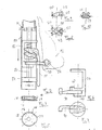
- Fig. 1 shows a profile piece 10 in the form of a tube, which is formed with a continuous longitudinal slot 12.
- a disc 14 is screwed, riveted, glued or welded, which has a base plate 16 and an annular edge 18.
- the ring 18 is provided with a recess and the plate is formed with an extension 20.
- 4 and 5 shows the disc 14 in section and in plan view.
- a rod 22 is attached, which can consist of a solid rod or a tube.
- the rod 22 is non-rotatably connected to the disc 14.
- the upper end of the rod 22 is provided with a locking ring 24.
- a locking mechanism 26 is displaceable.
- the locking mechanism consists of a U-shaped bracket 28, in the free legs 30, 32 through openings 34, 36 out forms are.
- the free ends of the legs 30 and 32 protrude into the longitudinal slot 12, so that the locking mechanism 26 is rotatably on the rod 22.
- a pawl 40 Arranged between the legs 30 and 32 is a pawl 40 which can be driven via a lever 38 and a pawl 42 which is in contact with the pawl 40 and is in contact with the underside of the leg 30.
- a compression spring in the form of a coil spring 44 is provided between the lower leg 32 and the underside of the pawl 40.
- the pawl 40 has a through opening 46 and the pawl 42 has a through opening 48 through which the rod 22 is guided.
- a roller 50 is mounted, on which the inner end 52 of the lever 38 engages when the lever 38 is pivoted downward. Due to the one-sided mounting of the pawl 42 on the underside of the leg 30, the pawl is tilted, the through hole 48 of which is somewhat larger than the diameter of the rod 22, so that the pawl wedges on the rod 22. This causes the locking mechanism 26 to lock itself automatically. When the lever 38 is pivoted downward, the locking pawl 42 is raised because the locking pawl 40 is wedged on the rod 22.
- a contact surface with a pin 54 is formed on the top of the leg 30, a contact surface with a pin 54 is formed.
- the pin 54 engages in the lower end of a mast 56, which is received within the profile 10.
- a reinforcing ring 58 is arranged, which prevents the mast 56 from pushing apart the slot 12 when large forces are applied. Reinforcement tapes can be arranged over the length of the profile piece 10 if necessary.
- a fastening element 60 Arranged below the locking mechanism 26 is a fastening element 60, which consists of a leg provided with a through hole 62, on which a projecting leg 64 is provided at the outer end, so that a receiving hook for a clevis 66 of a sail 68 is created.
- the fastener 60 can ver on the rod 22 are pushed and due to the eccentrically acting forces, the element on the rod 22 cant, so that it can be arranged in any position without an unwanted displacement along the rod 22.
- a fastening 70 for, for example, a wire rope is arranged on the pawl 22, which is guided through the slot 12 to the outside, so that it can be pulled by hand.
- the lower end of the mast 56 is inserted into the profile 10 of the device until it rests on the top of the U-shaped bracket 28. Then the eyelet 66 is hooked onto the hook 64. The lever 38 is now pivoted downward, whereby the locking mechanism 26 and thus the mast are raised. The pivoting movement of the lever 38 is repeated until the required tension is present in the sail and in the mast, i.e. until the required distance between the fastener 60 and the locking mechanism 26 is reached.
- the device at the lower end of which a joint in the form of a power joint 72 (FIG. 3) and a pin for locking on the board (not shown), is attached to the board.
- FIG. 8 to 10 show the pawl 42 in different views.
- Fig. 8 shows the pawl 42 in plan view.
- the through bore 48, the roller 50 and the fastening 70 for the pull rope for quick adjustment of the locking mechanism 26 can be seen. From FIG. 8 it can be seen that the axis of the through bore 48 is inclined at an angle to the longitudinal axis of the rod 22.
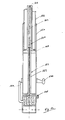
- Fig. 2 shows an embodiment consisting of a profile piece 80, in which a locking mechanism 82 is slidably arranged on a rod 86 attached to a disc 84.
- the locking mechanism 82 is rotated by 180 ° with respect to the locking mechanism 26 of FIG. 1, so that when a lever 88 is actuated, the locking mechanism 82 is moved downward.
- a fastening element 90 is fastened to the locking mechanism 82 and is displaced downward with it, as a result of which a sail 92 is tensioned, which is attached to the fastening element 90 with a eyelet 94.
- the design of the locking mechanism with the pawls and the mode of operation is analogous to that described with reference to FIG. 1.
- the end of the mast is supported on a contact surface 81 which is arranged in the profile piece 80.
- the height of this contact surface 81 can be arranged in the profile piece 80 or on the rod 86.
- FIG. 6 shows the bracket 96 of the locking device 82 with the fastening element 90 arranged thereon.
- FIG. 7 shows a view of the underside of the bracket 96, in which the fastening element 90 is arranged between a lower leg 98 and a further leg 100.
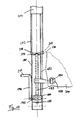
- FIG. 11 shows a device consisting of a tubular profile 110.
- the inner surface of the profile 110 is formed with an internal thread 112.
- a rod 114 is rotatably mounted on a plate 116 inside the profile 110.
- a gear 120 is arranged between the plate 116 and a guide plate 118 and engages with a pinion 122 on the underside of the rod 114.
- a worm or a bevel gear of the gear 120 is rotated via a crank 124, whereby the rod 114 is rotated about its longitudinal axis.
- a longitudinal groove 126 is formed on the rod 114, in which a rib 128 engages, which is provided on the inside of a through hole 130 of a disk 132.
- the washer 132 is formed with an external thread 134 that fits into the internal thread 112 in the profile 110 takes hold.
- the rod 114 is rotated and with this the disc 132. Since the external thread of the disc 132 engages in the internal thread 112, the disc 132 is raised or lowered depending on the direction of rotation of the disc 132, the rib or Spring 128 slides in the groove 126.
- the mast can be raised via the disc 132, on the upper side of which an extension 136 is formed for centering the lower end of a mast 138, while at the same time a sail, which is attached to a fastening element 140 with a loop, is tensioned. Only a very small force is required to adjust the mast in the device according to the invention via the crank and the gear.
- FIG. 12 shows a device for adjusting and tensioning a mast and a sail with a profile piece 150 in the form of a tube.
- a piston-cylinder unit 152 is provided within the tube 150 and can be operated pneumatically or hydraulically via a lever 154.
- the lower end of a mast 156 rests on the collar 158 of a cylinder 160 which is raised when hydraulic fluid or compressed air is directed into the space 164 through the piston 162.
- a screw 166 is provided for ventilation.
- a screw 168 can be rotated to lower the cylinder 160.
- a fastening device 170 is arranged on the outside of the profile 150, to which a lie can be attached via an eyelet.
- Fig. 13 shows a profile piece 180 in the form of a tube, which is formed with a longitudinal slot 182.
- discs 184 and 186 are fastened, in which a screw spindle 188 is rotatably mounted.
- a gear 192 which can be actuated via a hand crank 190, is accommodated in the form of a worm gear or a countershaft, via which the screw spindle 188 is rotated.
- the screw spindle 188 has at its upper end within the tube 180 Bearing washer 194.
- a fastening element 196 for hanging an eyelet 198 of a sail 200 is arranged on the screw spindle 188.
- the fastening element 196 is displaced in the vertical direction on the profile piece 180. This either pulls the sail 200 down and tensioned or releases the tension so that the sail can be removed from the fastener 196.
- a contact surface 206 is attached to the outside of the profile piece 180.
- the upper end of the profile piece 180 is received in the lower end 202 of the mast 204.
- the profile piece 180 can be provided with an external thread onto which the contact surface 206 is screwed in the form of two nuts 208 and 210 provided with an internal thread. The arrangement of two nuts can be countered so that an immovable contact surface is formed for the mast during use.
- the hand crank 190 can be detachable from the gearbox or the handle 212 can be pivoted up or down so that no protruding elements are arranged on the mast base.
Landscapes
- Chemical & Material Sciences (AREA)
- Engineering & Computer Science (AREA)
- Combustion & Propulsion (AREA)
- Mechanical Engineering (AREA)
- Ocean & Marine Engineering (AREA)
- Clamps And Clips (AREA)
Applications Claiming Priority (4)
| Application Number | Priority Date | Filing Date | Title |
|---|---|---|---|
| DE3626918 | 1986-08-08 | ||
| DE3626918 | 1986-08-08 | ||
| DE3633752 | 1986-10-03 | ||
| DE19863633752 DE3633752A1 (de) | 1986-10-03 | 1986-10-03 | Vorrichtung zum befestigen des mastes und zum spannen des segels des riggs eines windsurfboards |
Publications (2)
| Publication Number | Publication Date |
|---|---|
| EP0257410A2 true EP0257410A2 (fr) | 1988-03-02 |
| EP0257410A3 EP0257410A3 (fr) | 1988-09-21 |
Family
ID=25846387
Family Applications (1)
| Application Number | Title | Priority Date | Filing Date |
|---|---|---|---|
| EP87111458A Ceased EP0257410A3 (fr) | 1986-08-08 | 1987-08-07 | Dispositif de fixation d'un mât et tendeur pour la voile du gréement d'une planche à voile |
Country Status (1)
| Country | Link |
|---|---|
| EP (1) | EP0257410A3 (fr) |
Cited By (3)
| Publication number | Priority date | Publication date | Assignee | Title |
|---|---|---|---|---|
| US4977843A (en) * | 1989-08-28 | 1990-12-18 | Ewert Charles F | Sail tensioning apparatus |
| GB2269148A (en) * | 1992-07-30 | 1994-02-02 | David John Penfold | A rotary operated mast extension e.g. for a windsurfing mast |
| FR3149860A1 (fr) | 2023-05-17 | 2024-12-20 | Franck Gressier | Système de réglage de tension pour cordage applicable aux pieds de mat de planche à voile. |
Family Cites Families (2)
| Publication number | Priority date | Publication date | Assignee | Title |
|---|---|---|---|---|
| DE3241165A1 (de) * | 1982-11-08 | 1984-05-10 | Klaus-Jürgen 3500 Kassel Schmidtkunz | Segelsurfer |
| DE3526464A1 (de) * | 1985-07-24 | 1986-02-27 | Jörg 3050 Wunstorf Flemming | Vorliekspanner fuer ein segelbrett |
-
1987
- 1987-08-07 EP EP87111458A patent/EP0257410A3/fr not_active Ceased
Cited By (3)
| Publication number | Priority date | Publication date | Assignee | Title |
|---|---|---|---|---|
| US4977843A (en) * | 1989-08-28 | 1990-12-18 | Ewert Charles F | Sail tensioning apparatus |
| GB2269148A (en) * | 1992-07-30 | 1994-02-02 | David John Penfold | A rotary operated mast extension e.g. for a windsurfing mast |
| FR3149860A1 (fr) | 2023-05-17 | 2024-12-20 | Franck Gressier | Système de réglage de tension pour cordage applicable aux pieds de mat de planche à voile. |
Also Published As
| Publication number | Publication date |
|---|---|
| EP0257410A3 (fr) | 1988-09-21 |
Similar Documents
| Publication | Publication Date | Title |
|---|---|---|
| DE2442798C2 (de) | Vorrichtung zum Ein- oder Ausschrauben von insbesondere schweren Schraubenbolzen | |
| EP1810791B1 (fr) | Dispositif pour comprimer un ressort hélicoidal d'un ensemble ressort - amortisseur | |
| DE3636566A1 (de) | Spannvorrichtung fuer blasdorne von blasformmaschinen | |
| DE2618877C3 (de) | Vorrichtung zum Kontern und Brechen der Gewindeverbindungen zwischen Rohrkörpern | |
| DE102009046443A1 (de) | Wechselarmatur für Sensoren mit Betätigungssicherung | |
| EP0257410A2 (fr) | Dispositif de fixation d'un mât et tendeur pour la voile du gréement d'une planche à voile | |
| DE3633752A1 (de) | Vorrichtung zum befestigen des mastes und zum spannen des segels des riggs eines windsurfboards | |
| DE4304992A1 (de) | Vorrichtung zum Spannen von Brettern, insbesondere Fußbodenbrettern | |
| EP0324899B1 (fr) | Accessoire pour baignoire | |
| DE3608401C2 (fr) | ||
| EP0344635A1 (fr) | Dispositif pour la fixation de conteneurs | |
| DE8710851U1 (de) | Vorrichtung zum Befestigen des Mastes und zum Spannen des Segels des Riggs eines Windsurfboardes | |
| DE2908176A1 (de) | Autodach-lasttraeger | |
| DE4103809A1 (de) | Werkzeugfuehrung | |
| DE19508508A1 (de) | Arbeitshilfe zum Abziehen von an Wänden angeworfenem Putz | |
| DE3048862C2 (de) | Federspannvorrichtung zum Vorspannen von Schraubenfedern an Fahrwerksfederungen, insbesondere zum Montieren von Kraftfahrzeugen | |
| DE2640991B1 (de) | Schraubenspannvorrichtung zum OEffnen und Schliessen des Deckels eines Reaktorkessels | |
| AT392767B (de) | Vorrichtung zur verlaengerung des mastes eines riggs fuer ein segelbrett oder segelboot | |
| DE10362070B4 (de) | Christbaumständer | |
| DE503589C (de) | Auf einem Fahrgestell senkrecht verschiebbare Spannsaeule | |
| DE4015445A1 (de) | Vorrichtung zum spannen eines werkstuecktraegers | |
| DE19506417A1 (de) | Vorrichtung zum Errichten eines Schutzgeländers im Bereich des Ortgangs eines Hausdaches | |
| DE20023309U1 (de) | Baumständer, insbesondere Christbaumständer | |
| DE803409C (de) | Setzvorrichtung fuer eiserne Grubenstempel und Verfahren zum Setzen von zweiteiligen Grubenstempeln | |
| DE3930766C1 (en) | Erecting device for hospital bed aid - comprises support tube and bearer tube with fitted clamping slide for handle |
Legal Events
| Date | Code | Title | Description |
|---|---|---|---|
| PUAI | Public reference made under article 153(3) epc to a published international application that has entered the european phase |
Free format text: ORIGINAL CODE: 0009012 |
|
| AK | Designated contracting states |
Kind code of ref document: A2 Designated state(s): AT BE CH DE ES FR GB GR IT LI LU NL SE |
|
| RBV | Designated contracting states (corrected) |
Designated state(s): AT CH DE FR LI NL |
|
| PUAL | Search report despatched |
Free format text: ORIGINAL CODE: 0009013 |
|
| RHK1 | Main classification (correction) |
Ipc: B63B 35/72 |
|
| AK | Designated contracting states |
Kind code of ref document: A3 Designated state(s): AT CH DE FR LI NL |
|
| 17P | Request for examination filed |
Effective date: 19890512 |
|
| 17Q | First examination report despatched |
Effective date: 19900619 |
|
| STAA | Information on the status of an ep patent application or granted ep patent |
Free format text: STATUS: THE APPLICATION HAS BEEN REFUSED |
|
| 18R | Application refused |
Effective date: 19911228 |
|
| RIN1 | Information on inventor provided before grant (corrected) |
Inventor name: SCHLITTENBAUER, FRANZ Inventor name: RAITH, FRANZ XAVER |