EP0257487A2 - Funkenerosionselektrode - Google Patents
Funkenerosionselektrode Download PDFInfo
- Publication number
- EP0257487A2 EP0257487A2 EP87111818A EP87111818A EP0257487A2 EP 0257487 A2 EP0257487 A2 EP 0257487A2 EP 87111818 A EP87111818 A EP 87111818A EP 87111818 A EP87111818 A EP 87111818A EP 0257487 A2 EP0257487 A2 EP 0257487A2
- Authority
- EP
- European Patent Office
- Prior art keywords
- wire
- electrode
- copper
- wire electrode
- iron alloy
- Prior art date
- Legal status (The legal status is an assumption and is not a legal conclusion. Google has not performed a legal analysis and makes no representation as to the accuracy of the status listed.)
- Withdrawn
Links
Images
Classifications
-
- B—PERFORMING OPERATIONS; TRANSPORTING
- B23—MACHINE TOOLS; METAL-WORKING NOT OTHERWISE PROVIDED FOR
- B23H—WORKING OF METAL BY THE ACTION OF A HIGH CONCENTRATION OF ELECTRIC CURRENT ON A WORKPIECE USING AN ELECTRODE WHICH TAKES THE PLACE OF A TOOL; SUCH WORKING COMBINED WITH OTHER FORMS OF WORKING OF METAL
- B23H7/00—Processes or apparatus applicable to both electrical discharge machining and electrochemical machining
- B23H7/02—Wire-cutting
- B23H7/08—Wire electrodes
-
- Y—GENERAL TAGGING OF NEW TECHNOLOGICAL DEVELOPMENTS; GENERAL TAGGING OF CROSS-SECTIONAL TECHNOLOGIES SPANNING OVER SEVERAL SECTIONS OF THE IPC; TECHNICAL SUBJECTS COVERED BY FORMER USPC CROSS-REFERENCE ART COLLECTIONS [XRACs] AND DIGESTS
- Y10—TECHNICAL SUBJECTS COVERED BY FORMER USPC
- Y10T—TECHNICAL SUBJECTS COVERED BY FORMER US CLASSIFICATION
- Y10T428/00—Stock material or miscellaneous articles
- Y10T428/12—All metal or with adjacent metals
- Y10T428/12493—Composite; i.e., plural, adjacent, spatially distinct metal components [e.g., layers, joint, etc.]
- Y10T428/125—Deflectable by temperature change [e.g., thermostat element]
- Y10T428/12514—One component Cu-based
-
- Y—GENERAL TAGGING OF NEW TECHNOLOGICAL DEVELOPMENTS; GENERAL TAGGING OF CROSS-SECTIONAL TECHNOLOGIES SPANNING OVER SEVERAL SECTIONS OF THE IPC; TECHNICAL SUBJECTS COVERED BY FORMER USPC CROSS-REFERENCE ART COLLECTIONS [XRACs] AND DIGESTS
- Y10—TECHNICAL SUBJECTS COVERED BY FORMER USPC
- Y10T—TECHNICAL SUBJECTS COVERED BY FORMER US CLASSIFICATION
- Y10T428/00—Stock material or miscellaneous articles
- Y10T428/12—All metal or with adjacent metals
- Y10T428/12493—Composite; i.e., plural, adjacent, spatially distinct metal components [e.g., layers, joint, etc.]
- Y10T428/12771—Transition metal-base component
- Y10T428/12861—Group VIII or IB metal-base component
- Y10T428/12903—Cu-base component
- Y10T428/12917—Next to Fe-base component
- Y10T428/12924—Fe-base has 0.01-1.7% carbon [i.e., steel]
Definitions
- an electrical discharge machining electrode comprising an electrically conductive metal wire having an adherent carbon surface coating.
- a preferred embodiment of said wire electrode employs a molybdenum metal core having an oxidized surface and on which a surface carbon coating is deposited.
- a copper clad iron alloy wire produced by the well known dip-forming process is oxidized to provide a better metallurgically bonded substrate for the surface carbon coating.
- a known wire electrode member and apparatus for electrical discharge machining is described in U.S. Patent 4,287,404 wherein the electrically conductive metal wire is provided with an active surface comprising at least 50% by weight of a metal or alloy selected from a group consisting of zinc, cadmium, tin, lead, antimony and bismuth.
- the active surface coating is continuously replenished during the machining operation by passage through an electrolytic bath containing the selected active metal. Such continuous replenishment of the active surface while the workpiece is being machined understandably renders the equipment more complex to build and operate.
- the replated wire electrode is said to further require resizing with a die prior to its being fed to the machining zone.
- an adherent carbon coating provides the active surface for said electrical discharge machining electrode to provide a higher metal removal rate from the workpiece without accompanying need to continuously replace the active surface material.
- Other benefits attributable to said carbon or graphite surface on the machining electrode include low friction with the wire guides enabling offset of the wire electrode member for taper cuts and/or higher back tensions which is desirable for wire alignment without producing vibration.
- a 0.004 inch diameter electrode having the carbon surface coating deposited on a molybdenum core permitted machining of tool steel at thicknesses up to 4 inches with only a minor reduction in the metal removal rate at increased workpiece thickness and no wire breakage.
- a further desirable objective is to improve the cutting action for this type wire electrode without requiring that the machining process or apparatus utilize higher levels of electrical power to achieve the same degree of cutting action.
- a particular configuration for this type electrical discharge machining electrode wire provides improved cutting action wherein said machining process can be carried out at the same level of electrical power being applied to said wire electrode.
- the presently improved wire electrode member provides faster cutting action at the same wire diameter than the aforementioned carbon coated molybdenum core wire and does so with no increase in the level of electrical power that is applied to the electrode.
- a further related benefit has been discovered with respect to such utilization of the present improved electrode whereby the surface finish in the region of the metal workpiece where cutting action has occurred is also related to the cutting speed and with both of said operating parameters being further related to the current level applied to this wire electrode.
- an increase in cutting speed produces rougher surface finish and with increased current levels being applied to the wire electrode yielding a rougher surface finish and/or a faster cutting speed.
- An advantage derived from such relationship is to produce a smoother surface finish with less current being supplied to the wire electrode member at a given cutting speed.
- the novel wire electrode member according to the present invention comprises an iron alloy core coated with an intermediate layer including a copper and zinc heat reaction product on which is deposited an adherent carbon surface coating.
- a preferred method of fabricating said wire electrode member employs a ferrous alloy metal core, such as nickel-iron or low carbon steel which has been copper clad by an already well known dip-forming process and deposits the zinc coating on said copper clad member by other also well known techniques such as electroplating or immersion in a bath of molten metal.
- the copper clad core utilizes a sufficient copper thickness such that it becomes only partially converted during a subsequent heat treatment to produce alloying action with the overlying zinc coating.
- the copper clad wire now sold by General Electric Company under the tradename "Cumet" and which exhibits electrical conductivity approximately 60% that exhibited by OFHC copper wire is a preferred core material as compared with the Cumet wire having a lesser copper cladding and exhibiting only 40% of said electrical conductivity standard. Accordingly, a zinc coating in the thickness range of 0.004 inch or greater for a 0.030 inch diameter size of the 60% Cumet wire has been found to retain a residual copper layer beneath the alloyed copper and zinc medium in the final electrode member and which is believed to further enhance electrical power delivery to the spark discharge.
- the zinc coated intermediate product is next coated with a commercial liquid suspension of graphite, such as "Aquadag” or “Electrodag” which are both products sold by the Acheson Colloids Company.
- graphite such as "Aquadag” or "Electrodag” which are both products sold by the Acheson Colloids Company.
- the latter graphite coating material is preferred for the present electrode member by reason of its higher electrical conductivity thereby enabling higher energy delivery by the finished electrode to the metal workpiece.
- Subsequent heating of such multilayer coated iron alloy wire under conditions producing an alloying reaction between the underlying zinc and copper substrates in said coating results in the desired metallurgical bonding of the above defined intermediate metal layers with further mechanical bonding of the overlying surface carbon particulates.
- Such mechanical bonding of the active carbon surface is also believed to be a contributing factor for the improved performance discovered by enhancing thermal and electrical conductivity in the wire electrode member.
- a final step in such wire electrode fabrication which further improves mechanical adherence by a consolidation of the
- Superior cutting action by the presently improved wire electrode member is believed primarily attributable to the above defined novel construction.
- the iron alloy core permits the electrode member to carry higher loads through the machining zone when used lessening the incidence of wire breakage as well as improving the accuracy of the cutting action. Longer continuous cutting action is thereby made possible with said electrode construction. While such core portion is initially produced in the preferred embodiments by means of a dip-forming process (as further described in U.S. patents 3,008,201 and 3,060,053) and lacks optimum physical strength due to an annealed condition produced when the zinc coated core is thermally processed, the mechanical drawing step subsequently given to the fabricated electrode member raises the strength for said overall construction.
- the ultimate tensile strength of this final electrode construction having a low carbon steel core has been found to exceed that for a conventional brass EDM wire electrode by at least 25% at the discharge machining temperatures.
- the copper and zinc alloy inner layer of the present electrode surface contributes to a faster cutting action from improved flushing activity in the discharge machining zone.
- some retention of an unconverted copper layer in said intermediate layer construction is preferred to increase both thermal and electrical conductivity in the final electrode member.
- Such innerlayer construction helps offset both lower thermal and electrical conductivity of the iron alloy core thereby enhancing higher metal removal rates.
- Further improved bonding of an active carbon surface in the present electrode member by means of said copper and zinc innerlayer should also enhance metal removal rates by delivering electrical power to the spark discharge more effectively.
- a preferred wire electrode member fabricated in the above described manner utilizes a low carbon steel alloy core clad with sufficient copper to exhibit electrical conductivity approximately 60% that exhibited by OFHC copper wire at an initial wire diameter size of 0.025 inch.
- the copper clad wire is thereafter zinc plated by conventional electroplating to plating thicknesses of 0.003-0.004 inch and then coated with the above specified graphite materials preparatory to heating at the elevated temperatures forming a partial or complete alloy between the copper and zinc undercoatings. Satisfactory alloying action can be achieved by transporting the multilayer coated wire electrode through a hydrogen atmosphere furnace heated to approximately 750°C at a 10 foot per minute wire travel speed.
- a different wire electrode member according to the present invention features a nickel-iron core with an intermediate layer of a brass alloy formed by partial conversion of the underlying copper and zinc coatings as above described.
- Carrying out the electrical discharge machining process generally comprises moving the electrically charged wire electrode member in close proximity to a metal workpiece so as to cause a spark discharge therebetween, said wire electrode member having the hereinbefore described configuration, contacting the gap space between said workpiece surface and the moving wire electrode member with a moving dielectric liquid, removing metal from the workpiece and carbon from the wire electrode member with said spark discharge, and displacing the removed metal and carbon from the gap space in the moving dielectric fluid.
- a conventional EDM machine such as the commercially available ELOX equipment is supplied with a spool of the present wire electrode material for single pass mode of operation.
- the surface graphite along with the intermediate copper and zinc alloy are volatilized during such operation with the volatilized by-products providing effective flushing of the gap space and with the cutting action thereby achieved in said process being superior at the same level of electrical power being applied to said wire electrode.
- said improved cutting action can be increased cutting speed at the same electrical power level as compared with prior art wire electrodes or a smoother surface finish being achieved at a given speed with less current being applied to the present wire electrode.
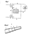
- FIG. 1 is shown a fragmentary view depicting the present wire electrode member 10 while being used in the operation of an otherwise conventional EDM machine.
- Said wire electrode member 10 is suspended between a pair of guide rollers 12 and 14 to travel downwardly in a vertical direction and produce a spark discharge (not shown) causing the machining action to take place.
- the metal workpiece 16 being machined in said manner is positioned in close proximity to said continuously moving electrode wire member at a distance producing the spark discharge therebetween when said wire electrode member and workpiece are properly interconnected in a conventional EDM electrical circuit.
- said electrical circuit employs a pair of brush contacts 18 and 20 to contact said electrode member and which are suitably further connected by conductors 24 and 26, respectively, to a conventional EDM power source 22.
- a supply of moving dielectric fluid 17 such as deionized water is also provided at the gap space location to remove the metal particulates caused by action of the spark discharge and the workpiece along with the carbon particulates and subjacent alloy being volatilized from the present wire electrode member during such use.
- the preferred Cumet wire electrode of the invention exhibited a 43% increase in cutting speed as compared with an uncoated brass wire and a 9% cutting speed increase as compared with a zinc coated brass wire.
- the machine #2 comparison further illustrates such cutting action improvement over the same uncoated brass wire at all levels of electrical power being applied to each type electrode. While it should be noted in the foregoing comparisons that the particular modified Cumet wire tested had been fabricated with copper clad wire exhibiting the preferred 60% electrical conductivity before modification, a lesser thickness copper clad wire fabrication also demonstrates this improvement over the same prior art EDM electrodes. For example, other Cumet wire clad with a copper thickness exhibiting but 40% electrical conductivity as compared with OFHC copper wire but otherwise processed according to the present invention has also been found superior in cutting action to said prior art electrodes.
- FIG 2 there is shown in perspective the composite construction of a preferred wire electrode member according to the present invention.
- said wire electrode member 10 consists of an iron alloy core 30, having intermediate layers of unalloyed copper 32 supporting a copper and zinc alloy layer 34 formed in the hereinbefore described manner and which serve to mechanically bond a surface carbon coating 36 deposited thereon.
- the particular wire electrode of the invention employed in the foregoing test comparison was fabricated in such manner commencing with a 0.003 inch thickness zinc electroplate having been deposited on the surface of a 0.025 inch diameter Cumet wire.
- An Electrodag graphite surface coating was thereafter applied and followed by heat treatment employed to convert a major portion of the zinc and copper coatings to a brass alloy. After recoating the heat treated wire with an Electrodag deposit, the final wire diameter of 0.010 inch was provided by mechanical drawing action.
Landscapes
- Chemical & Material Sciences (AREA)
- Chemical Kinetics & Catalysis (AREA)
- Electrochemistry (AREA)
- Engineering & Computer Science (AREA)
- Mechanical Engineering (AREA)
- Electrical Discharge Machining, Electrochemical Machining, And Combined Machining (AREA)
- Non-Insulated Conductors (AREA)
Applications Claiming Priority (2)
| Application Number | Priority Date | Filing Date | Title |
|---|---|---|---|
| US06/901,087 US4740666A (en) | 1986-08-28 | 1986-08-28 | Electrical discharge machining electrode |
| US901087 | 1986-08-28 |
Publications (2)
| Publication Number | Publication Date |
|---|---|
| EP0257487A2 true EP0257487A2 (de) | 1988-03-02 |
| EP0257487A3 EP0257487A3 (de) | 1989-01-25 |
Family
ID=25413581
Family Applications (1)
| Application Number | Title | Priority Date | Filing Date |
|---|---|---|---|
| EP87111818A Withdrawn EP0257487A3 (de) | 1986-08-28 | 1987-08-14 | Funkenerosionselektrode |
Country Status (3)
| Country | Link |
|---|---|
| US (1) | US4740666A (de) |
| EP (1) | EP0257487A3 (de) |
| JP (1) | JPS63114817A (de) |
Families Citing this family (18)
| Publication number | Priority date | Publication date | Assignee | Title |
|---|---|---|---|---|
| US4988552A (en) * | 1988-06-17 | 1991-01-29 | Composite Concepts Company | Electrical discharge machining electrode |
| JP2901838B2 (ja) * | 1992-05-20 | 1999-06-07 | プラクスエア・エス・ティー・テクノロジー・インコーポレイテッド | コロナ装置 |
| US5762726A (en) | 1995-03-24 | 1998-06-09 | Berkenhoff Gmbh | Wire electrode and process for producing a wire electrode, particular for a spark erosion process |
| US5808262A (en) * | 1995-06-07 | 1998-09-15 | Swil Limited | Wire electrode for electro-discharge machining and method of manufacturing same |
| US6897400B1 (en) | 2004-03-16 | 2005-05-24 | General Electric Company | Out flushing guide bushing |
| US8067689B2 (en) * | 2005-12-01 | 2011-11-29 | Composite Concepts Company | EDM wire |
| JP4943827B2 (ja) * | 2006-11-30 | 2012-05-30 | 矢崎総業株式会社 | 抵抗溶接方法及び導体ユニット |
| US10189100B2 (en) * | 2008-07-29 | 2019-01-29 | Pratt & Whitney Canada Corp. | Method for wire electro-discharge machining a part |
| JP2010100226A (ja) * | 2008-10-24 | 2010-05-06 | Kanto Auto Works Ltd | バックドア |
| WO2012012701A1 (en) * | 2010-07-23 | 2012-01-26 | Innovative Technology Providers, Llc | Graphitized edm wire |
| CN102784978A (zh) * | 2011-05-20 | 2012-11-21 | 昆山市瑞捷精密模具有限公司 | 慢走丝电火花线切割铜合金电极线及其制备方法 |
| US9878387B2 (en) | 2012-05-08 | 2018-01-30 | United Technologies Corporation | Electrical discharge machining electrode |
| EP3053688B1 (de) | 2015-02-06 | 2019-10-09 | Agie Charmilles SA | Graphenelektrode und Verfahren zur Herstellung einer solchen Elektrode |
| US11511362B2 (en) * | 2019-02-05 | 2022-11-29 | Cap Technologies, Llc | Wire for electric discharge machining |
| CN110125499B (zh) * | 2019-05-14 | 2020-12-08 | 宁波博德高科股份有限公司 | 表层含碳的慢走丝电火花加工用电极丝及其制备方法 |
| US11013158B1 (en) * | 2020-08-17 | 2021-05-18 | Micrometal Technologies, Inc. | Electrical shielding material composed of metallized stainless steel or low carbon steel monofilament yarns |
| CN115958262B (zh) * | 2023-01-30 | 2025-07-11 | 宁波博威合金精密细丝有限公司 | 一种慢走丝电火花加工用电极丝 |
| CN116000393B (zh) * | 2023-02-08 | 2025-07-15 | 宁波博威合金精密细丝有限公司 | 一种单向走丝电火花加工用电极丝 |
Family Cites Families (16)
| Publication number | Priority date | Publication date | Assignee | Title |
|---|---|---|---|---|
| CA623087A (en) * | 1961-07-04 | National-Standard Company | Zinc over copper on steel wire | |
| CA793785A (en) * | 1968-09-03 | Yajima Takashi | Process of making a composite metallic product consisting of ferrous material and cupriferous material | |
| CA701901A (en) * | 1965-01-12 | General Electric Company | Method of coating with carbon | |
| CA714011A (en) * | 1965-07-20 | N.V. Philips Gloeilampenfabrieken | Method of providing molybdenum wire with a carbon coating | |
| US2317350A (en) * | 1938-11-01 | 1943-04-27 | Nat Standard Co | Copper clad wire and method of preparing the same |
| US2378458A (en) * | 1943-05-24 | 1945-06-19 | American Steel & Wire Co | Galvanizing methods |
| US3008201A (en) * | 1955-08-24 | 1961-11-14 | Gen Electric | Apparatus for the continuous formation of intermediates |
| US2904717A (en) * | 1958-06-06 | 1959-09-15 | Sylvania Electric Prod | Composite electrode structure |
| US3060053A (en) * | 1960-09-12 | 1962-10-23 | Gen Electric | Method and apparatus for accreting molten copper on a moving member |
| US3838188A (en) * | 1972-06-29 | 1974-09-24 | Carborundum Co | Vacuum baked composite molded carbonaceous electrodes |
| JPS5322930A (en) * | 1976-08-17 | 1978-03-02 | Komatsu Ltd | Exhaust valv e |
| GB2015909B (en) * | 1978-03-03 | 1982-12-01 | Charmilles Sa Ateliers | Electrode for spark erosion machining |
| SE444278B (sv) * | 1979-10-11 | 1986-04-07 | Charmilles Sa Ateliers | Tradformig elektrod samt sett att tillverka sadan elektrod |
| CH645831A5 (fr) * | 1981-10-09 | 1984-10-31 | Charmilles Sa Ateliers | Procede et machine pour le decoupage. |
| JPS58155127A (ja) * | 1982-03-09 | 1983-09-14 | Mitsubishi Electric Corp | ワイヤカツト放電加工用ワイヤ電極 |
| US4686153A (en) * | 1984-12-08 | 1987-08-11 | Fujikura Ltd. | Electrode wire for use in electric discharge machining and process for preparing same |
-
1986
- 1986-08-28 US US06/901,087 patent/US4740666A/en not_active Expired - Fee Related
-
1987
- 1987-08-14 EP EP87111818A patent/EP0257487A3/de not_active Withdrawn
- 1987-08-26 JP JP62210394A patent/JPS63114817A/ja active Pending
Also Published As
| Publication number | Publication date |
|---|---|
| JPS63114817A (ja) | 1988-05-19 |
| US4740666A (en) | 1988-04-26 |
| EP0257487A3 (de) | 1989-01-25 |
Similar Documents
| Publication | Publication Date | Title |
|---|---|---|
| US4740666A (en) | Electrical discharge machining electrode | |
| US4287404A (en) | Electrode for electrical discharge machining | |
| JP3718529B2 (ja) | 放電加工用多孔性電極線の製造方法 | |
| KR920010862B1 (ko) | 와이어컷방전 가공용 와이어전극 | |
| CN102922065A (zh) | 用于放电加工的电极丝和用于制造该电极丝的方法 | |
| US20050040141A1 (en) | Wire for high-speed electrical discharge machining | |
| US4717804A (en) | EDM wire electrode | |
| JP2644911B2 (ja) | 放電加工用ワイヤ型電極及びその製造方法 | |
| JPH11347848A (ja) | スパ―クエロ―ジョン電極ワイヤ―の製造方法と製造装置 | |
| JP2713350B2 (ja) | ワイヤ放電加工用電極線 | |
| JPS648706B2 (de) | ||
| JPS61109623A (ja) | ワイヤ放電加工用電極線およびその製造方法 | |
| JPS62246425A (ja) | ワイヤ放電加工用電極線 | |
| JPH06158385A (ja) | 通電ロール | |
| JP2000107943A (ja) | ワイヤ放電加工用電極線 | |
| JPS61117021A (ja) | ワイヤ放電加工用電極線およびその製造方法 | |
| KR100481950B1 (ko) | 흑연 코팅 방전 가공용 전극선 제조방법 | |
| EP0799665B1 (de) | Verfahren zur Herstellung einer Drahtelektrode zum Funkenerodieren | |
| JP2005085590A (ja) | 複合被覆銅線、複合被覆エナメル銅線および複合被覆融着エナメル銅線 | |
| JPS62255015A (ja) | ワイヤ放電加工用電極線 | |
| JPS60104616A (ja) | 放電加工用電極線の製造方法 | |
| JPS5921946B2 (ja) | 錫または半田メツキ線の製造方法 | |
| JPS62157724A (ja) | 放電加工用電極線 | |
| JPH0790381B2 (ja) | アルミニウム合金板の電気抵抗スポット溶接方法 | |
| JPH09195085A (ja) | 高耐食性錫めっき鋼板の製造法 |
Legal Events
| Date | Code | Title | Description |
|---|---|---|---|
| PUAI | Public reference made under article 153(3) epc to a published international application that has entered the european phase |
Free format text: ORIGINAL CODE: 0009012 |
|
| AK | Designated contracting states |
Kind code of ref document: A2 Designated state(s): CH DE FR GB IT LI SE |
|
| PUAL | Search report despatched |
Free format text: ORIGINAL CODE: 0009013 |
|
| AK | Designated contracting states |
Kind code of ref document: A3 Designated state(s): CH DE FR GB IT LI SE |
|
| STAA | Information on the status of an ep patent application or granted ep patent |
Free format text: STATUS: THE APPLICATION IS DEEMED TO BE WITHDRAWN |
|
| 18D | Application deemed to be withdrawn |
Effective date: 19890726 |
|
| RIN1 | Information on inventor provided before grant (corrected) |
Inventor name: TOMALIN, DANDRIDGE SALE Inventor name: CAPP, JOHN |