EP0257594B1 - Système d'enregistrement de données à inscription unique pour milieu optique - Google Patents
Système d'enregistrement de données à inscription unique pour milieu optique Download PDFInfo
- Publication number
- EP0257594B1 EP0257594B1 EP87112181A EP87112181A EP0257594B1 EP 0257594 B1 EP0257594 B1 EP 0257594B1 EP 87112181 A EP87112181 A EP 87112181A EP 87112181 A EP87112181 A EP 87112181A EP 0257594 B1 EP0257594 B1 EP 0257594B1
- Authority
- EP
- European Patent Office
- Prior art keywords
- writing
- data
- reading
- sector
- recorded
- Prior art date
- Legal status (The legal status is an assumption and is not a legal conclusion. Google has not performed a legal analysis and makes no representation as to the accuracy of the status listed.)
- Expired - Lifetime
Links
- 230000003287 optical effect Effects 0.000 title claims description 30
- 238000000034 method Methods 0.000 claims description 10
- 238000012544 monitoring process Methods 0.000 claims description 4
- 238000001514 detection method Methods 0.000 description 2
- 238000006243 chemical reaction Methods 0.000 description 1
- 230000007423 decrease Effects 0.000 description 1
- 230000000593 degrading effect Effects 0.000 description 1
- 238000010586 diagram Methods 0.000 description 1
- 230000010287 polarization Effects 0.000 description 1
- 238000002310 reflectometry Methods 0.000 description 1
- 230000002441 reversible effect Effects 0.000 description 1
Images

Classifications
-
- G—PHYSICS
- G11—INFORMATION STORAGE
- G11B—INFORMATION STORAGE BASED ON RELATIVE MOVEMENT BETWEEN RECORD CARRIER AND TRANSDUCER
- G11B27/00—Editing; Indexing; Addressing; Timing or synchronising; Monitoring; Measuring tape travel
- G11B27/10—Indexing; Addressing; Timing or synchronising; Measuring tape travel
- G11B27/19—Indexing; Addressing; Timing or synchronising; Measuring tape travel by using information detectable on the record carrier
- G11B27/28—Indexing; Addressing; Timing or synchronising; Measuring tape travel by using information detectable on the record carrier by using information signals recorded by the same method as the main recording
- G11B27/30—Indexing; Addressing; Timing or synchronising; Measuring tape travel by using information detectable on the record carrier by using information signals recorded by the same method as the main recording on the same track as the main recording
- G11B27/3027—Indexing; Addressing; Timing or synchronising; Measuring tape travel by using information detectable on the record carrier by using information signals recorded by the same method as the main recording on the same track as the main recording used signal is digitally coded
-
- G—PHYSICS
- G11—INFORMATION STORAGE
- G11B—INFORMATION STORAGE BASED ON RELATIVE MOVEMENT BETWEEN RECORD CARRIER AND TRANSDUCER
- G11B20/00—Signal processing not specific to the method of recording or reproducing; Circuits therefor
- G11B20/10—Digital recording or reproducing
- G11B20/12—Formatting, e.g. arrangement of data block or words on the record carriers
- G11B20/1215—Formatting, e.g. arrangement of data block or words on the record carriers on cards
-
- G—PHYSICS
- G11—INFORMATION STORAGE
- G11B—INFORMATION STORAGE BASED ON RELATIVE MOVEMENT BETWEEN RECORD CARRIER AND TRANSDUCER
- G11B7/00—Recording or reproducing by optical means, e.g. recording using a thermal beam of optical radiation by modifying optical properties or the physical structure, reproducing using an optical beam at lower power by sensing optical properties; Record carriers therefor
- G11B7/007—Arrangement of the information on the record carrier, e.g. form of tracks, actual track shape, e.g. wobbled, or cross-section, e.g. v-shaped; Sequential information structures, e.g. sectoring or header formats within a track
- G11B7/013—Arrangement of the information on the record carrier, e.g. form of tracks, actual track shape, e.g. wobbled, or cross-section, e.g. v-shaped; Sequential information structures, e.g. sectoring or header formats within a track for discrete information, i.e. where each information unit is stored in a distinct discrete location, e.g. digital information formats within a data block or sector
-
- G—PHYSICS
- G11—INFORMATION STORAGE
- G11B—INFORMATION STORAGE BASED ON RELATIVE MOVEMENT BETWEEN RECORD CARRIER AND TRANSDUCER
- G11B2220/00—Record carriers by type
- G11B2220/20—Disc-shaped record carriers
- G11B2220/21—Disc-shaped record carriers characterised in that the disc is of read-only, rewritable, or recordable type
- G11B2220/215—Recordable discs
- G11B2220/218—Write-once discs
Definitions
- the present invention relates to a write-once data writing system for optical recording medium of a type wherein a data track includes a plurality of sectors each having at least a preamble and data.
- an optical recording medium has recording areas on which data is recorded as a pattern of changes in optical nature of the medium such as, reflectivity, transmissivity, polarization and the like.
- the patterns of changes are recorded by causing spots on the recording area to be physically or chemically transformed.
- Such changes are not reversible in most of optical recording media, which means that it is impposible to rewrite the data once written.
- there is a type of optical recording medium which allows additional data to be recorded only on areas not recorded yet.
- preamble information as sync regions operable in reading the recorded data.
- the additional data recording may be performed a track-by-track or sector-by-sector manner.
- the track is divided into a pluratity of sectors each capable of storing a fixed or variable number of data with the preamble added at the beginning of each sector before recording data in the sector.
- US-A-4,594,701 discloses an apparatus and method for recording of data on an optical recording medium.
- a new recording of data is added to the end of a previously recorded track by first playing back the recorded track and detecting the position on the track where data ceases to be stored. Additional data is then recorded sector by sector at the region following the recorded region.
- the track-by-track additional data recording system causes additional data to be recorded on a blank track separate from a recorded track even though the additional data is continued from the data on the recorded track. This results in a complex sequence of reading a series of data, increasing an access time.
- this system does not satisfy the requirement that additional data is desirably recorded at area following the area, on the same track, at which data is previously recorded.
- this system requires a number of blank tracks for recording additional data while leaving a lot of areas unused on a recorded track, degrading cost-performance and availability of recording area.
- the sector-by-sector additional data recording system permits a series of data to be recorded continuously and in a sector-by-sector manner on the same track, which decreases unused area on each track, increasing availability of the recording area.
- the previously recorded data on the track is first read out to find the end in a reading mode and then the additional data is written in a writing mode.
- the data writing is quite different from the data reading in their operation speed due to difference in their function. That is, it takes a certain time in the writing mode to cause a phisical or chemical transfomation with a light beam like a laser beam directed at a position on the optical recording medium while in the reading mode the operation is done almost instantaneously to detect, using a light beam, the change in optical state due to the previously formed phisical or chemical transformation. Therefore, the moving rate of the light beam for data writing is different from that for data reading. This results in complex control not only in timing for switching the mode from reading to writing but in setting of start position for writing.
- the present invention has been made to obviate the problems as described above and it is an object of the present invention to provide a write-once data writing system for optical recording medium which enables us to write a series of data continuously on the same track.
- a write-once data writing method for optical recording medium of a type which allows a data track to contain a plurality of sectors each storing at least data and a preamble having sync information comprising the steps of: detecting in a reading mode the recorded sector on a data track, on which additional data is to be recorded; writing additional data sector-by-sector at a region following a recorded region characterised by: performing said detecting step with said writing/reading head being moved at a reading rate; providing a deceleration region, at a position following the last recorded sector on said track, of a length corresponding to a deceleration time necessary to change the relative moving rate of said writing/reading head with respect to the optical recording medium from one for reading to another for writing; decelerating the head to a writing rate during said deceleration region; and beginning to write the additional data.
- a write-once data writing apparatus for optical recording medium of a type which allows a data track to contain a plurality of sectors each storing at least data and a preamble having sync information
- the apparatus comprising: a writing/reading head; a drive circuit for moving said writing/reading head relative to an optical recording medium along the data track thereon at respective rates in writing and reading data; writing means for applying data to be recorded to said head and controlling the writing operation; reading means for processing signals detected by said head to retrieve control signals, data, etc.; mode switching means responsive to an instruction to record additional data, for first directing said drive circuit and said reading means to a reading mode and for then directing, when receiving a mode switching signal, the same to a writing mode; characterised in that: mode change judging means is responsive to said instruction, for monitoring the output from said reading means to detect the end of a sector and check whether the preamble is included in the next sector, and for generating said mode switching signal if no preamble is found;
- the term "sector" is usually used in association with a disc type recording medium to represent a block of recording area on a track which is divided into a plurality of the blocks. In the present specification and the attached claims, the term is also applied to a card type recording medium to stand for the similar conception.
- the sector may be of a fixed or variable length. In the case of the variable length, an end mark or pattern may be recorded at the end of each sector.
- the end of the previously recorded sector on a data track, on which additional data is to be recorded is detected through reading by the writing/reading head at a rate in a reading mode, and if no preamble is detected within a predetermined time after detecting the end of the sector, then the relative moving rate of the head is decelerated, while defining a deceleration region, to a writing rate to start the writing.
- said drive circuit preferably has a function to decelerate the relative moving rate of the head in response to the mode switching signal until the rate reaches the writing rate, and then apply to a write enable signal to said writing means.
- said deceleration region is set having a length corresponding to the deceleration time necessary for the head to decelerate from the reading rate to the writing rate and a timing is set for beginning to write the additional data at a position following the deceleration region.
- the data is written sector by sector with the preamble added before the data in each sector in the same manner as the previously recorded sectors.
- the present invention employing a sector-by-sector data writing, enables us to write a series of data continuously on the same track with less unused area in each track, increasing the availability of the recording area.
- the present invention provides a deceleration region, at a position following the last recorded sector on a track including both recorded and blank sectors, of a length corresponding to a deceleration time necessary to change mode from reading mode to writing mode, the relative moving rate of the head with respect to the recording medium can be decelerated from the reading rate to the writing rate during the head has passed the deceleration region.
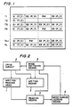
- Figure 1 illustrates a configuration of the optical recording medium embodying a write-once data writing method according to the present invention.
- the present invention is applied to a card type of optical recording medium.
- a plurality of tracks T1-Tn are disposed in pararell on a surface of the card type recording medium.
- data is written sector by sector like sectors S1,S2,...
- Each sector contains a preamble P and data D.
- the sector is of a fixed length in this embodiment.
- the detection of the available area is done through reading, by the head, recorded information on the recorded sectors sequentially from the beginning of the track. Thus, previously recorded sectors S are detected along with its end portion. If no preamble is detected from the next sector, there is no more sectors previously recorded and the head reaches available area. Then, writing/reading control advice (not shown) switches the mode of the read/write head from reading to writing.
- the moving rate of the writing/reading head reaches a normal writing rate in a predetermined time after the head began to decelerate.
- the deceleration region RW is set corresponding to the predetermined time. That is, the deceleration region is set as an elapsed time in an operation control program.
- the deceleration region appears on the optical recording medium as a blank area with no data recorded.
- the length of this area is constant on condition that the reading and writing rates are fixed. Therefore, it is possible to achieve normal data writing if the writing is started a predetermined time after switching the mode.
- timing and position for starting the writing are determined with reference to the time a predetermined period elapsed after the mode switching. Accordingly, the timing and position setting are set only by monitoring the elapsed time with a simple control.
- the data is sequentially read from the biginning end in the same manner as described above.
- the head When the head has reached the deceleration region WR, it skips the region with no deceleration accompanied unlike the case in the additional data writing.
- the difference in operation can be achieved, for example, by software control.
- figure 2 shows a preferred one of such apparatuses.
- the apparatus in figure 2 comprises writing/reading head 1, drive circuit 2 for moving the head relative to an optical recording medium along the data track thereon at respective rates in writing and reading data, writing means 3 for applying data to be recorded to the head 1 and for controlling the writing operation, and reading means 4 for processing signals detected by the head 1 to read control signals, data, etc.
- This configuration is similar to the known writing/reading apparatus.
- the apparatus of this embodiment further conprises mode switching means 5 responsive to an instruction to record additional data, for first directing the drive circuit 2 and the reading means 4 to a reading mode and for then directing them to a writing mode in response to a mode switching signal, and mode changing judging means 6, responsive to said instruction, for checking through monitoring the output from said reading means 4 if the preamble is, after detecting the end of a sector, included in the next sector, and for generating said mode switching signal if no preamble is detected.
- the mode switching means 5 and the mode change judging means 6 operate together as the above-mentioned writing/reading control device.
- Drive circuit 2 causes the head 1 to move along a desired or target track at a reading rate while allowing reading means 4 to read the recorded information (step 1).
- Reading means 4 sends the information to mode switching means 6 which detects, from the information, the end of each recorded sector and a preamble in the following sector. If no preamble is detected after detecting the last recorded sector, the mode switching means 6 outputs a mode switching signal (steps 2-4).
- mode switching means 5 causes drive circuit 2 to decelerate the moving rate of head 1 so that the moving rate is altered from the reading rate to the writing rate (step 5).
- the drive circuit 2 keeps checking if the moving rate has reached the desired writing rate, and then generates a write enable signal (steps 6 and 7).
- Writing means 3 enables, in response to the write enable signal, head 1 to write additional data while causing the additional data to be applied to the head 1 (step 8).
- mode change judging means 6 keeps, after reading one sector, seaching the succeeding preamble for a period longer than the deceleration time. If the succeeding preamble is found during the period, the data reading is continued. Thus, the deceleration region RW is skipped in reading with no problem.
Landscapes
- Engineering & Computer Science (AREA)
- Signal Processing (AREA)
- Optical Recording Or Reproduction (AREA)
- Signal Processing For Digital Recording And Reproducing (AREA)
Claims (2)
- Système d'enregistrement de données à inscription unique pour milieu optique du type permettant à une piste de données de contenir plusieurs secteurs mettant chacun en mémoire au moins des données et un préambule contenant des informations sync, le système comprenant les étapes suivantes :
la détection en mode de lecture du secteur enregistré sur une piste de données sur laquelle des données supplémentaires doivent être enregistrées;
l'enregistrement des données supplémentaires secteur par secteur dans une région suivant une région déjà enregistrée, caractérisé par :
l'exécution de ladite étape de détection avec ladite tête de lecture et d'enregistrement déplacée à une vitesse de lecture;
la création d'une région de décélération à un endroit suivant le dernier secteur déjà enregistré sur ladite piste et ayant une longueur correspondant au temps de décélération nécessaire pour modifier la vitesse de déplacement relative de ladite tête d'enregistrement et d'écriture par rapport au milieu optique d'enregistrement, d'une position de lecture à une autre position d'enregistrement;
la décélération de la tête jusqu'à une vitesse d'enregistrement pendant ladite période de décélération; et
le début de l'enregistrement de données supplémentaires. - Appareil d'enregistrement de données à inscription unique pour milieu optique du type permettant à une piste de données de contenir plusieurs secteurs mettant chacun en mémoire au moins des données et un préambule ayant des informations sync, l'appareil comprenant :
une tête de lecture et d'enregistrement (1);
un circuit de commande (2) pour déplacer ladite tête de lecture et d'enregistrement (1) par rapport à un milieu d'enregistrement optique le long d'une piste de données sur celui-ci à des vitesses correspondantes pour l'enregistrement et la lecture des données;
un moyen d'enregistrement (3) pour introduire les données enregistrées dans ladite tête et pour contrôler l'opération d'enregistrement;
un moyen de lecture (4) pour traiter les signaux détectés par ladite tête afin de rechercher des signaux de contrôle de données, etc.;
un moyen de commutation de mode (5) réagissant à une instruction d'enregistrer des données supplémentaires en faisant tout d'abord mettre ledit circuit de commande (2) et ledit moyen de lecture (4) en mode de lecture et en mettant ensuite ceux-ci en mode d'enregistrement à la réception d'un signal de commutation de mode, caractérisé en ce que :
un moyen d'évaluation du changement de mode (16) qui réagit à ladite instruction pour surveiller la sortie dudit moyen de lecture (4) afin de détecter la fin d'un secteur et de vérifier si le préambule est inclus dans le secteur suivant et pour produire ledit signal de commutation de mode si aucun préambule n'est trouvé;
ledit circuit de commande (2) réagissant audit moyen de commutation de mode provoque une décélération de la vitesse de déplacement jusqu'à ce que la vitesse atteigne une vitesse d'enregistrement et envoie ensuite un signal d'autorisation d'enregistrement audit moyen d'enregistrement.
Applications Claiming Priority (2)
| Application Number | Priority Date | Filing Date | Title |
|---|---|---|---|
| JP196797/86 | 1986-08-22 | ||
| JP61196797A JPS6361426A (ja) | 1986-08-22 | 1986-08-22 | 光記録媒体のデ−タ追記方式 |
Publications (3)
| Publication Number | Publication Date |
|---|---|
| EP0257594A2 EP0257594A2 (fr) | 1988-03-02 |
| EP0257594A3 EP0257594A3 (fr) | 1991-04-10 |
| EP0257594B1 true EP0257594B1 (fr) | 1993-08-11 |
Family
ID=16363810
Family Applications (1)
| Application Number | Title | Priority Date | Filing Date |
|---|---|---|---|
| EP87112181A Expired - Lifetime EP0257594B1 (fr) | 1986-08-22 | 1987-08-21 | Système d'enregistrement de données à inscription unique pour milieu optique |
Country Status (5)
| Country | Link |
|---|---|
| US (1) | US4815062A (fr) |
| EP (1) | EP0257594B1 (fr) |
| JP (1) | JPS6361426A (fr) |
| CA (1) | CA1301320C (fr) |
| DE (1) | DE3786962D1 (fr) |
Families Citing this family (8)
| Publication number | Priority date | Publication date | Assignee | Title |
|---|---|---|---|---|
| JPS6435762A (en) * | 1987-07-31 | 1989-02-06 | Canon Kk | Optical information recording and reproducing device |
| JPH01130324A (ja) * | 1987-11-16 | 1989-05-23 | Olympus Optical Co Ltd | 光学的記録再生装置 |
| GB8916306D0 (en) * | 1989-07-17 | 1989-08-31 | Unilever Plc | Fabric softening composition |
| EP0833338B1 (fr) * | 1993-01-06 | 2006-04-05 | Sony Corporation | Procédé d'enregistrement d'un milieu d'enregistrement |
| JP3517907B2 (ja) | 1993-10-08 | 2004-04-12 | ソニー株式会社 | ディスク記録装置 |
| JP3503231B2 (ja) * | 1994-11-30 | 2004-03-02 | ソニー株式会社 | 記録装置 |
| US20060173890A1 (en) * | 2003-07-19 | 2006-08-03 | Uwe Janssen | Method and data carrier for handling a database |
| US8095576B2 (en) * | 2006-11-06 | 2012-01-10 | Panasonic Corporation | Recording device |
Family Cites Families (18)
| Publication number | Priority date | Publication date | Assignee | Title |
|---|---|---|---|---|
| US4145758A (en) * | 1977-10-25 | 1979-03-20 | Drexler Technology Corporation | Error checking method and apparatus for digital data in optical recording systems |
| US4375091A (en) * | 1978-06-30 | 1983-02-22 | Discovision Associates | Method and apparatus for information retrieval from an optically readable storage medium |
| US4278756A (en) * | 1979-07-06 | 1981-07-14 | Drexler Technology Corporation | Reflective data storage medium made by silver diffusion transfer |
| US4278758A (en) * | 1979-07-06 | 1981-07-14 | Drexler Technology Corporation | Process for making a reflective data storage medium |
| US4269917A (en) * | 1979-07-06 | 1981-05-26 | Drexler Technology Corporation | Data storage medium having reflective particulate silver layer |
| JPS5753879A (en) * | 1980-09-12 | 1982-03-31 | Victor Co Of Japan Ltd | High-speed searching system for reproducer of disk-shaped information recording medium |
| US4360728A (en) * | 1981-02-27 | 1982-11-23 | Drexler Technology Corporation | Banking card for automatic teller machines and the like |
| US4544835A (en) * | 1983-12-29 | 1985-10-01 | Drexler Technology Corporation | Data system containing a high capacity optical contrast laser recordable wallet-size plastic card |
| US4500777A (en) * | 1981-02-27 | 1985-02-19 | Drexler Technology Corporation | High data capacity, scratch and dust resistant, infrared, read-write data card for automatic teller machines |
| US4542288A (en) * | 1981-02-27 | 1985-09-17 | Drexler Technology Corporation | Method for making a laser recordable wallet-size plastic card |
| JPS5832236A (ja) * | 1981-08-18 | 1983-02-25 | Matsushita Electric Ind Co Ltd | 光学的記録再生装置 |
| JPS5862868A (ja) * | 1981-10-09 | 1983-04-14 | Pioneer Video Corp | 情報再生装置における高速アドレス情報探索方式 |
| JPS58166567A (ja) * | 1982-03-26 | 1983-10-01 | Matsushita Electric Ind Co Ltd | 情報トラックの検索装置 |
| JPS59188843A (ja) * | 1983-04-12 | 1984-10-26 | Fujitsu Ltd | 光学的デイスク装置 |
| JPS6050629A (ja) * | 1983-08-27 | 1985-03-20 | Sony Corp | 光デイスク記録装置 |
| US4594701A (en) * | 1983-10-31 | 1986-06-10 | Rca Corporation | System for recording data on spiral track |
| US4631706A (en) * | 1984-11-19 | 1986-12-23 | International Business Machines Corporation | System for preventing the overwriting of previously optically recorded data and for reading optically recorded data during writing |
| EP0200959A3 (fr) * | 1985-04-16 | 1987-12-16 | Hitachi, Ltd. | Système de commande pour moteur pas à pas |
-
1986
- 1986-08-22 JP JP61196797A patent/JPS6361426A/ja active Pending
-
1987
- 1987-08-21 US US07/088,726 patent/US4815062A/en not_active Expired - Fee Related
- 1987-08-21 DE DE8787112181T patent/DE3786962D1/de not_active Expired - Lifetime
- 1987-08-21 EP EP87112181A patent/EP0257594B1/fr not_active Expired - Lifetime
- 1987-08-24 CA CA000545145A patent/CA1301320C/fr not_active Expired - Fee Related
Also Published As
| Publication number | Publication date |
|---|---|
| JPS6361426A (ja) | 1988-03-17 |
| EP0257594A2 (fr) | 1988-03-02 |
| US4815062A (en) | 1989-03-21 |
| DE3786962D1 (de) | 1993-09-16 |
| EP0257594A3 (fr) | 1991-04-10 |
| CA1301320C (fr) | 1992-05-19 |
Similar Documents
| Publication | Publication Date | Title |
|---|---|---|
| US4611314A (en) | Method for accessing to a rotating record medium and an access control system | |
| US5134602A (en) | Calibrating optical disk recorders to some parameters during disk spin up while deferring calibration of other parameters | |
| US5018124A (en) | Information recording method and apparatus for recording information on track positioned at least two tracks ahead when abnormality of tracking servo is detected | |
| EP0378449B1 (fr) | Système pour enregistrer et reproduire des informations | |
| US4815062A (en) | Write-once data writing system for optical recording medium | |
| US5081616A (en) | Positioning controller | |
| JPH1139659A (ja) | 光ディスク装置 | |
| EP0402071A2 (fr) | Circuit de traitement de signaux pour appareil magnéto-optique d'enregistrement/de reproduction | |
| JPS62131320A (ja) | 情報記憶システムの情報処理方法 | |
| US4875202A (en) | Disk-type storage medium recording/reproducing apparatus | |
| US20020046319A1 (en) | Packetized data information recording apparatus | |
| US5959797A (en) | Magnetic recording apparatus having means for reading data associated with a non-readable servo sector | |
| CA1270059A (fr) | Methode pour detecter la position d'une tete optique | |
| KR910006157B1 (ko) | 광기록 매체의 데이타 추가 기록방식 및 그 장치 | |
| JP2743848B2 (ja) | 再生方法 | |
| JPS61198466A (ja) | ホ−ムポジシヨン検出方法 | |
| US5926447A (en) | Method for enhancing the data access time in an optical disc apparatus | |
| JP2854438B2 (ja) | 光ディスク装置のアクセス制御方式 | |
| JP2719975B2 (ja) | 磁気記録再生装置におけるデータ記録方法 | |
| JPH0668603A (ja) | 光ディスク装置 | |
| JP2601615B2 (ja) | 情報記録方法 | |
| KR100255204B1 (ko) | 디스크 구동시스템의 데이타섹터 분할갭 보상 디스크장치 및 보상방법 | |
| JPH03108161A (ja) | 回転型情報記録再生装置および回転型情報記録媒体 | |
| JPH0498656A (ja) | トラックフォーマットの判別方法 | |
| JPH1021653A (ja) | 磁気ディスク装置 |
Legal Events
| Date | Code | Title | Description |
|---|---|---|---|
| PUAI | Public reference made under article 153(3) epc to a published international application that has entered the european phase |
Free format text: ORIGINAL CODE: 0009012 |
|
| AK | Designated contracting states |
Kind code of ref document: A2 Designated state(s): DE FR GB |
|
| PUAL | Search report despatched |
Free format text: ORIGINAL CODE: 0009013 |
|
| AK | Designated contracting states |
Kind code of ref document: A3 Designated state(s): DE FR GB |
|
| 17P | Request for examination filed |
Effective date: 19910718 |
|
| 17Q | First examination report despatched |
Effective date: 19911029 |
|
| GRAA | (expected) grant |
Free format text: ORIGINAL CODE: 0009210 |
|
| AK | Designated contracting states |
Kind code of ref document: B1 Designated state(s): DE FR GB |
|
| PG25 | Lapsed in a contracting state [announced via postgrant information from national office to epo] |
Ref country code: FR Effective date: 19930811 Ref country code: DE Effective date: 19930811 |
|
| REF | Corresponds to: |
Ref document number: 3786962 Country of ref document: DE Date of ref document: 19930916 |
|
| PGFP | Annual fee paid to national office [announced via postgrant information from national office to epo] |
Ref country code: GB Payment date: 19931206 Year of fee payment: 7 |
|
| EN | Fr: translation not filed | ||
| PLBE | No opposition filed within time limit |
Free format text: ORIGINAL CODE: 0009261 |
|
| STAA | Information on the status of an ep patent application or granted ep patent |
Free format text: STATUS: NO OPPOSITION FILED WITHIN TIME LIMIT |
|
| 26N | No opposition filed | ||
| PG25 | Lapsed in a contracting state [announced via postgrant information from national office to epo] |
Ref country code: GB Effective date: 19940821 |
|
| GBPC | Gb: european patent ceased through non-payment of renewal fee |
Effective date: 19940821 |