EP0257985B1 - Leitende Aufzeichnungselektrode für eine Druckvorrichtung - Google Patents
Leitende Aufzeichnungselektrode für eine Druckvorrichtung Download PDFInfo
- Publication number
- EP0257985B1 EP0257985B1 EP87307366A EP87307366A EP0257985B1 EP 0257985 B1 EP0257985 B1 EP 0257985B1 EP 87307366 A EP87307366 A EP 87307366A EP 87307366 A EP87307366 A EP 87307366A EP 0257985 B1 EP0257985 B1 EP 0257985B1
- Authority
- EP
- European Patent Office
- Prior art keywords
- ink
- electrode
- recording electrode
- narrow bore
- recording
- Prior art date
- Legal status (The legal status is an assumption and is not a legal conclusion. Google has not performed a legal analysis and makes no representation as to the accuracy of the status listed.)
- Expired - Lifetime
Links
- 238000007639 printing Methods 0.000 title claims description 12
- 230000005684 electric field Effects 0.000 claims description 7
- 238000004891 communication Methods 0.000 claims description 3
- 239000000463 material Substances 0.000 description 6
- 239000002184 metal Substances 0.000 description 5
- 238000001125 extrusion Methods 0.000 description 4
- 239000007788 liquid Substances 0.000 description 4
- 238000000465 moulding Methods 0.000 description 4
- PNEYBMLMFCGWSK-UHFFFAOYSA-N aluminium oxide Inorganic materials [O-2].[O-2].[O-2].[Al+3].[Al+3] PNEYBMLMFCGWSK-UHFFFAOYSA-N 0.000 description 3
- 239000011248 coating agent Substances 0.000 description 3
- 238000000576 coating method Methods 0.000 description 3
- 230000002093 peripheral effect Effects 0.000 description 3
- OKTJSMMVPCPJKN-UHFFFAOYSA-N Carbon Chemical compound [C] OKTJSMMVPCPJKN-UHFFFAOYSA-N 0.000 description 2
- 229930182556 Polyacetal Natural products 0.000 description 2
- 239000012141 concentrate Substances 0.000 description 2
- 239000004020 conductor Substances 0.000 description 2
- 238000001035 drying Methods 0.000 description 2
- 229920006324 polyoxymethylene Polymers 0.000 description 2
- 239000000843 powder Substances 0.000 description 2
- 239000011347 resin Substances 0.000 description 2
- 229920005989 resin Polymers 0.000 description 2
- 239000011230 binding agent Substances 0.000 description 1
- 229910052799 carbon Inorganic materials 0.000 description 1
- 238000010276 construction Methods 0.000 description 1
- 238000001704 evaporation Methods 0.000 description 1
- 230000008020 evaporation Effects 0.000 description 1
- 239000006247 magnetic powder Substances 0.000 description 1
- 238000000034 method Methods 0.000 description 1
- 239000000203 mixture Substances 0.000 description 1
- 238000005192 partition Methods 0.000 description 1
- 239000004033 plastic Substances 0.000 description 1
- 229920003023 plastic Polymers 0.000 description 1
- 238000005498 polishing Methods 0.000 description 1
- -1 polyethylene terephthalate Polymers 0.000 description 1
- 229920000139 polyethylene terephthalate Polymers 0.000 description 1
- 239000005020 polyethylene terephthalate Substances 0.000 description 1
- 238000000926 separation method Methods 0.000 description 1
Images


Classifications
-
- B—PERFORMING OPERATIONS; TRANSPORTING
- B41—PRINTING; LINING MACHINES; TYPEWRITERS; STAMPS
- B41J—TYPEWRITERS; SELECTIVE PRINTING MECHANISMS, i.e. MECHANISMS PRINTING OTHERWISE THAN FROM A FORME; CORRECTION OF TYPOGRAPHICAL ERRORS
- B41J2/00—Typewriters or selective printing mechanisms characterised by the printing or marking process for which they are designed
- B41J2/005—Typewriters or selective printing mechanisms characterised by the printing or marking process for which they are designed characterised by bringing liquid or particles selectively into contact with a printing material
- B41J2/01—Ink jet
- B41J2/015—Ink jet characterised by the jet generation process
- B41J2/04—Ink jet characterised by the jet generation process generating single droplets or particles on demand
- B41J2/06—Ink jet characterised by the jet generation process generating single droplets or particles on demand by electric or magnetic field
-
- B—PERFORMING OPERATIONS; TRANSPORTING
- B41—PRINTING; LINING MACHINES; TYPEWRITERS; STAMPS
- B41J—TYPEWRITERS; SELECTIVE PRINTING MECHANISMS, i.e. MECHANISMS PRINTING OTHERWISE THAN FROM A FORME; CORRECTION OF TYPOGRAPHICAL ERRORS
- B41J2/00—Typewriters or selective printing mechanisms characterised by the printing or marking process for which they are designed
- B41J2/005—Typewriters or selective printing mechanisms characterised by the printing or marking process for which they are designed characterised by bringing liquid or particles selectively into contact with a printing material
- B41J2/01—Ink jet
- B41J2/015—Ink jet characterised by the jet generation process
- B41J2/04—Ink jet characterised by the jet generation process generating single droplets or particles on demand
- B41J2/06—Ink jet characterised by the jet generation process generating single droplets or particles on demand by electric or magnetic field
- B41J2002/061—Ejection by electric field of ink or of toner particles contained in ink
Definitions
- This invention relates to a printing device which forms a large number of dots on a record medium so as to print a picture image of a character, a figure or the like by a combination of such printed dots, and particularly to a printing device of the type mentioned wherein liquid ink is electrostatically projected to form dots on a record medium.
- ink jet printers wherein liquid ink drops are jetted from a nozzle in order to form a picture image on a record medium.
- An ink jet printer produces little noises, and where multi-colour printing is effected, it is superior with respect to the running cost and so on when compared with various other printing systems.
- choking of an ink nozzle, arising from evaporation of the ink still occur and cause problems in practical use of ink jet printers.
- a printer of a different type is disclosed in Japanese Patent Applications Nos: 54-23534 and 59-159355 wherein magnetic ink is magnetically introduced to end portions of needle members along outer peripheries of the needle members and is then caused to fly by an electric field applied between the needle members and an opposing electrode which is located similarly in an opposing relationship to the needle members with a record medium interposed therebetween.
- the printer as disclosed in Japanese Patent Application Nos: 56-170 and 56 4467 has the drawback that the structure for causing ink to come out as ink drops from the opening in the form of a slit is critical and lacks stability. In other words, the amount or direction in which the ink flies is not fixed and consequently the shape and position of a dot formed on a record medium is unreliable. Accordingly, printing of a high quality is difficult to attain. Meanwhile, the printer as disclosed in Japanese Patent Application Nos: 54-23534 and 59-159355 has the drawback that ink of a desired colour cannot always be available because magnetic ink, which must be used in order to introduce ink to ends of the needle members, is often the colour of the magnetic powder contained therein.
- EP-A-0121,242 provides a dot printer for magnetic ink including a plurality of tapered needles which optionally may each be provided with a plain axial bore.
- the plain axial bore may, however, become blocked by dry ink.
- the present invention is characterised in that the recording electrode for use in an ink jet printer has a narrow bore at its outer end from which ink is arranged to emerge as a jet, and a plurality of apertures of greater cross-section than said bore and defined by radial ribs which permit communication between said ink supply unit and the outer end of the electrode and so that the apertures open into said narrow bore whereby ink can be drawn by capillary action from said apertures and into said narrow bore to emerge as a narrow jet when an electric field is applied.
- ink is supplied at a high speed from the narrow bore to the end portion of the recording electrode by capillary action while ink comes around in the aperture which communicates with the narrow bore. Accordingly, drying of the ink in the narrow bore and resultant choking thereof can be prevented. In addition, the necessity of use of magnetic ink is eliminated, and consequently selection of any desired colour is possible.
- the printing device includes a printer body 1 in which a carrier 3 is mounted for sliding movement on a guide shaft 2.
- An opposing electrode 4 extends in parallel with the guide shaft 2 in the printer body 1 and a tractor 6 for feeding record sheet 5 as a record medium is also located in the printer body 1.
- a print head 7 is carried on the carrier 3.
- the print head 7 is shown in Figures 5 and 6.
- the print head 7 includes an ink vessel 9 in which ink 8 is stored, and a plurality of recording electrodes 10 located in the ink vessel 9.
- the ink 8 may be ordinary ink having a specific resistance higher than 10 6 ⁇ cm, a coefficient of viscosity lower than 10 mPas (cp) and a surface tension smaller than 2X10 ⁇ 4 Newtons/cm (20 dyn/cm); thus ink other than magnetic ink may be used.
- the recording electrodes 10 extend at end portions thereof outwardly through electrode holes 9a formed in the ink vessel 9 and are thus opposed to the opposing electrode 4. Rear end portions of the recording electrodes 10 are held by conductor lines 11 secured to a printed circuit board 12 which covers the ink vessel 9.
- the recording electrodes 10 are electrically connected, via the conductor lines 11 and the printed circuit board 12 and further via a connector 13 and switches 14, to power sources 15, 16 connected to the opposing electrode 4.
- a controlling circuit 17 for selectively switching the switches 14 is connected to the switches 14 as shown in Figure 5.
- the switches 14 and the controlling circuit 17 constitute a driving means 25 together with the power sources 15 and 16.
- the recording electrodes 10 are formed by extrusion molding of a polyacetal resin as a moulding material and coating on the surface of each of such moulded body a thin metal film 18.
- Each of the recording electrodes 10 has a conical portion 19 formed at an end portion thereof so that it has a taper shape at the end thereof.
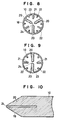
- Each of the recording electrodes 10 is a hollow clinder provided internally with four main ribs 20, four intermediate ribs 21 and eight small ribs 22 formed sequentially in the radial direction along the entire length of the recording electrode 10 on an inner circumferential wall of the hollow cylinder.
- the ribs extend radially toward the axis of the recording electrode 10 so as to serve as partition walls but such that radially inner ends of the main ribs 20, the ribs 21 and the small ribs 22 do not interfere with each other.
- the spacing defined by the radial inner ends of the main ribs 20 constitutes a narrow bore 24 while the spacings defined by the main ribs 20 the ribs 21 and the small ribs 22 constitute apertures 23 which communicate with the narrow bore 24.
- the main ribs 20, the ribs 21 and the small ribs 22 are respectively identically shaped. Accordingly, the narrow bore 24 is located at the centre of the cross-section of the recording electrode 10 and extends from the rear end of the recording electrode 10 to the apex of the conical portion 19 throughout the recording electrode 10.
- the apertures 23 extend from the rear end of the recording electrode 10 and terminate at an outer peripheral face of the conical portion 19 of the recording electrode 10.
- the main ribs 20 and the ribs 21, 22 have concavities formed on surfaces thereof, thereby forming portions of larger sectional area and portions of smaller sectional area in the apertures 23 and the narrow bore 24. It is to be noted that the minimum diameter of the narrow bore 24 should be less than 100 microns and especially, for example, 30 microns to 50 microns.
- burrs may appear on a plished surface. Because such burrs may cause choking of the narrow bore 24 or deform the cross-sectional shape of the narrow bore 24 and/or the apertures 23, the outer peripheral face of the conical portion 19 is preferably finished by dry honing. In this case, an Alundum (RTM) grain of 800 mesh is suitable.
- ink 8 which forms at the end of the recording electrode 10 receives an electrostatic force and is thus caused to fly toward the opposing electrode 4.
- the ink 8 thus projected clings to record paper 5 and forms a dot on the latter so that a character or a figure may be drawn by a selected group of such ink dots.
- the apertures 23 suck ink 8 from within the ink vessel 9 due to capillary action while the narrow bore 24 having a small sectional area sucks ink 8 at a high speed from within the apertures 23 of a greater sectional area by capillary action. Since in this instance the ink 8 is taken up sufficiently into the apertures 23 to form a body of the ink 8 within the recording electrode 10, drying of the ink 8 within the recording electrode 10 is prevented.
- the ink transfer operation by a capillary action can be accelerated at the portions of smaller sectional area while the ink is maintained in the form of liquid at the portions of greater sectional area so that choking of the recording electrode 10 can be prevented.
- the ink 8 is projected in use not from a slit portion buty from an end portion of the recording electrode 10 in the form of a needle. Accordingly, the ink 8 is smoothly separated from the end portion of the recording electrode 10, and consequently a fixed amount of ink 8 is projected in a predetermined direction. The consequent stable printing conditions lead to an impvement in print quality. Further, since the end portion of the recording electrode 10 is tapered at the conical portion 19, an electric field tends to concentrate at the apex of the conical portion 19 due to its distance and shape. This enhances the separation and stability of ink 8 further.
- the narrow bore 24 which supplies ink 8 at a high speed extends through the apex of the conical portion 19.
- ink 8 can be readily supplied to the apex of the conical portion 19. It will be noted that, at the instant when ink 8 files from the end portion of the recording electrode 10, ink 8 is supplied to the narrow bore 24 not only by capillary action but also by ink 8 being supplied from the apertures 23. If the diameter of the narrow bore 24 is increased too much, a depression will appear in a surface of ink at the open end of the narrow bore 24 as shown in Figure 7(b), This can deform the shape of an ink drop as it leaves the apex of the electrode 10.
- the ink drop will generally concentrate at the centre of the narrow bore 24 as shown in Figure 7(a), although this may depend on the characteristics of ink 8 employed in the actual embodiment. Accordingly, where ink 8 of a particular characteristic is used, a holding profile of ink 8 as shown in Figure 7(a) may sometimes be realized even if the minimum diameter of the narrow bore 24 is greater than 1000 microns.
- ink 8 is supplied to the electrode 10 by a capillary action, ordinary ink can be used in the printing device, and accordingly an ink of a vivid colour can be used if desired.
- the recording electrode 10 may be any recording electrode having a structure as listed below:
- a recording electrode of the structure (i) above is superior in regard to ink resisting property to a recording electrode made of a polyacetal resin material, and the strength of a thin metal film for coating can be increased.
- the step of coating a thin metal film after extrusion moulding can be omitted.
- the recording electrode 10 need not have a cylindrical profile but may be any profile such as an elliptical or polygonal profile, or a profile having a step or shoulder at an intermediate portion. Alternatively a profile having different sectional shapes at front and rear end portions may be used. In other words, the form of the profile is not limited.
- such a modified structure may be employed that the recording electrodes 10 are moved toward and away from the opposing electrode 4 while a fixed potential is applied between the opposing electrode 4 and the recording electrodes 10.
- a fixed potential is applied between the opposing electrode 4 and the recording electrodes 10.
- FIGs 8 and 9 Modified forms of the recording electrode 10 are shown in Figures 8 and 9.
- a recording electrode 10 is shown wherein a narrow bore 24 is defined by radially inward ends of three main ribs 20 which extend radially toward the centre of the section of the recording electrode 10.
- Figure 9 shows a recording electrode 10 which includes two main ribs 20 therein.
- a narrow bore 24 is formed only in an end portion of the recording electrode 10 and communicates with apertures 23 which extend from the front end to the rear end of the recording electrode 10.
- ink 8 will be supplied from a rear end portion of the recording electrode 10 into the narrow bore 24 through the aperture 23 principally by a capillary phenomenon.
- the ink 8 will then be supplied to the front end of the recording electrode in the narrow bore 24 by capillary action.
Landscapes
- Particle Formation And Scattering Control In Inkjet Printers (AREA)
Claims (2)
- Schreibelektrode (10) zum Einsatz in einem Tintenstrahldrukker, die eine Tintenzufuhreinheit (9) enthält, mit der die Elektrode in Verbindung steht, sowie eine Gegenelektrode (4), auf die die Elektrode einen Tintenstrahl zum Drucken auf ein Schreibmedium richtet,
dadurch gekennzeichnet, daß die Elektrode (10) eine schmale Bohrung (24) an ihrem äußeren Ende aufweist, aus der Tinte als Strahl austritt, sowie eine Vielzahl von Öffnungen (23) mit größerer Querschnittsfläche als die Bohrung, die durch radiale Rippen begrenzt werden, die Verbindung zwischen der Tintenzufuhreinheit (9) und dem äußeren Ende der Elektrode ermöglichen, und die so sind, daß sich die Öffnungen in die schmale Bohrung öffnen, wodurch Tinte durch Kapillarwirkung aus den Öffnungen in die schmale Bohrung (24) gezogen werden kann und als schmaler Strahl austritt, wenn ein elektrisches Feld angelegt wird. - Elektrode nach Anspruch 1, dadurch gekennzeichnet, daß an den Oberflächen der radialen Rippen Hohlrundungen ausgeformt sind, so daß Abschnitte mit großer Querschnittsfläche und Abschnitte mit kleinerer Querschnittsfläche in den Öffnungen (23) beziehungsweise der schmalen Bohrung (24) gebildet werden.
Applications Claiming Priority (2)
| Application Number | Priority Date | Filing Date | Title |
|---|---|---|---|
| JP200392/86 | 1986-08-27 | ||
| JP61200392A JPS6356455A (ja) | 1986-08-27 | 1986-08-27 | 印字装置 |
Publications (3)
| Publication Number | Publication Date |
|---|---|
| EP0257985A2 EP0257985A2 (de) | 1988-03-02 |
| EP0257985A3 EP0257985A3 (en) | 1989-10-25 |
| EP0257985B1 true EP0257985B1 (de) | 1993-07-28 |
Family
ID=16423562
Family Applications (1)
| Application Number | Title | Priority Date | Filing Date |
|---|---|---|---|
| EP87307366A Expired - Lifetime EP0257985B1 (de) | 1986-08-27 | 1987-08-20 | Leitende Aufzeichnungselektrode für eine Druckvorrichtung |
Country Status (4)
| Country | Link |
|---|---|
| US (1) | US4768044A (de) |
| EP (1) | EP0257985B1 (de) |
| JP (1) | JPS6356455A (de) |
| DE (1) | DE3786724T2 (de) |
Families Citing this family (9)
| Publication number | Priority date | Publication date | Assignee | Title |
|---|---|---|---|---|
| US4868585A (en) * | 1986-03-24 | 1989-09-19 | Tokyo Electric Co., Ltd. | Ink dot printer |
| DE3867979D1 (de) * | 1987-09-11 | 1992-03-05 | Tokyo Electric Co Ltd | Drucker. |
| US5363124A (en) * | 1993-01-26 | 1994-11-08 | Videojet Systems International, Inc. | Printhead for ink jet printers |
| US5576750A (en) * | 1994-10-11 | 1996-11-19 | Lexmark International, Inc. | Reliable connecting pathways for a three-color ink-jet cartridge |
| US6092889A (en) * | 1995-09-13 | 2000-07-25 | Kabushiki Kaisha Toshiba | Ink-jet head and ink-jet recording device each having a protruded-type electrode |
| JP2783230B2 (ja) * | 1995-12-18 | 1998-08-06 | 日本電気株式会社 | 静電式インクジェット記録ヘッド |
| US5901425A (en) | 1996-08-27 | 1999-05-11 | Topaz Technologies Inc. | Inkjet print head apparatus |
| AU744879B2 (en) | 1997-09-19 | 2002-03-07 | Aclara Biosciences, Inc. | Apparatus and method for transferring liquids |
| DE19847421A1 (de) * | 1998-10-14 | 2000-04-20 | Easy Lab Gmbh | Pipettier- oder Dosierverfahren und -vorrichtung |
Family Cites Families (14)
| Publication number | Priority date | Publication date | Assignee | Title |
|---|---|---|---|---|
| US3052213A (en) * | 1958-12-17 | 1962-09-04 | Ibm | Electrostatic printer apparatus for printing with liquid ink |
| DE2154472C3 (de) * | 1971-11-02 | 1975-05-15 | Casio Computer Co., Ltd., Higashiyamato, Tokio (Japan) | Düsenanordnung für ein Tintenstrahlschreibwerk |
| JPS4940432A (de) * | 1972-08-21 | 1974-04-16 | ||
| JPS5919819B2 (ja) * | 1977-07-22 | 1984-05-09 | 松下電器産業株式会社 | 画像記録方法 |
| JPS6059869B2 (ja) * | 1979-06-22 | 1985-12-27 | 日本電信電話株式会社 | インク記録用ヘツド |
| JPS56170A (en) * | 1979-06-15 | 1981-01-06 | Nippon Telegr & Teleph Corp <Ntt> | Ink recording system |
| JPS5738163A (en) * | 1980-08-18 | 1982-03-02 | Matsushita Electric Ind Co Ltd | Image recording method and apparatus therefor |
| JPS57188382A (en) * | 1981-05-15 | 1982-11-19 | Ricoh Co Ltd | Ink type wire printer |
| JPS59159355A (ja) * | 1983-03-01 | 1984-09-08 | Matsushita Electric Ind Co Ltd | 磁性インク記録装置 |
| DE3475598D1 (en) * | 1983-03-25 | 1989-01-19 | Ici Plc | Spraying apparatus |
| EP0121241B1 (de) * | 1983-03-30 | 1988-03-09 | Idemitsu Kosan Company Limited | Verfahren zur Herstellung von hochmolekularen Organoaluminiumpolymeren |
| EP0195652B1 (de) * | 1985-03-22 | 1988-11-23 | Tokyo Electric Co. Ltd. | Tintenpunktdrucker |
| JPS61235157A (ja) * | 1985-04-12 | 1986-10-20 | Tokyo Electric Co Ltd | 静電印刷方法 |
| US4710784A (en) * | 1985-07-11 | 1987-12-01 | Tokyo Electric Co., Ltd. | Ink jet printing device |
-
1986
- 1986-08-27 JP JP61200392A patent/JPS6356455A/ja active Pending
-
1987
- 1987-08-20 DE DE87307366T patent/DE3786724T2/de not_active Expired - Fee Related
- 1987-08-20 EP EP87307366A patent/EP0257985B1/de not_active Expired - Lifetime
- 1987-08-20 US US07/087,214 patent/US4768044A/en not_active Expired - Fee Related
Also Published As
| Publication number | Publication date |
|---|---|
| DE3786724T2 (de) | 1994-03-31 |
| US4768044A (en) | 1988-08-30 |
| JPS6356455A (ja) | 1988-03-11 |
| EP0257985A3 (en) | 1989-10-25 |
| EP0257985A2 (de) | 1988-03-02 |
| DE3786724D1 (de) | 1993-09-02 |
Similar Documents
| Publication | Publication Date | Title |
|---|---|---|
| US4555717A (en) | Ink jet printing head utilizing pressure and potential gradients | |
| EP0257985B1 (de) | Leitende Aufzeichnungselektrode für eine Druckvorrichtung | |
| DE69622621T2 (de) | Flüssigkeitsausstosskopf, Flüssigkeitsausstossvorrichtung und Flüssigkeitsausstossverfahren | |
| EP0196820B1 (de) | Tintenpunktdrucker | |
| JPH0437787B2 (de) | ||
| EP0941853A3 (de) | Tintenschreibervorrichtung | |
| EP0083249A1 (de) | Elektrostatisches Tintenstrahlsystem | |
| US4801952A (en) | Improved ink dot printer electrode structure | |
| US4868585A (en) | Ink dot printer | |
| EP0750989A2 (de) | Elektrostatischer Tintenstrahldruckkopf mit einer Elektrodenstapelstruktur | |
| JPS6283151A (ja) | 印刷装置 | |
| EP0844088A2 (de) | Elektrostatischer Tintenstrahldruckkopf und dessen Herstellungsverfahren | |
| JP2783230B2 (ja) | 静電式インクジェット記録ヘッド | |
| JPH08207318A (ja) | インクジェットプリンタ | |
| EP0882591B1 (de) | Elektrostatischer Tintenstrahldruckkopf mit einem mit konkaven und konvexen Teilen versehenen Kopfchip | |
| JP2859242B2 (ja) | 静電式インクジェット記録ヘッド | |
| JP2826535B2 (ja) | 静電式インクジェットプリントヘッド | |
| US4864327A (en) | Printer | |
| JPS6357249A (ja) | 印字装置 | |
| JP2783227B2 (ja) | 静電式インクジェット記録装置 | |
| KR910004027B1 (ko) | 잉크 도트 프린터 | |
| JP2842318B2 (ja) | 静電式インクジェット記録ヘッド | |
| JP2783224B2 (ja) | インクジェット式ヘッド装置 | |
| JPH0544346B2 (de) | ||
| JPH0462268B2 (de) |
Legal Events
| Date | Code | Title | Description |
|---|---|---|---|
| PUAI | Public reference made under article 153(3) epc to a published international application that has entered the european phase |
Free format text: ORIGINAL CODE: 0009012 |
|
| AK | Designated contracting states |
Kind code of ref document: A2 Designated state(s): DE FR GB |
|
| PUAL | Search report despatched |
Free format text: ORIGINAL CODE: 0009013 |
|
| AK | Designated contracting states |
Kind code of ref document: A3 Designated state(s): DE FR GB |
|
| 17P | Request for examination filed |
Effective date: 19900328 |
|
| 17Q | First examination report despatched |
Effective date: 19910905 |
|
| GRAA | (expected) grant |
Free format text: ORIGINAL CODE: 0009210 |
|
| AK | Designated contracting states |
Kind code of ref document: B1 Designated state(s): DE FR GB |
|
| PG25 | Lapsed in a contracting state [announced via postgrant information from national office to epo] |
Ref country code: FR Effective date: 19930728 |
|
| REF | Corresponds to: |
Ref document number: 3786724 Country of ref document: DE Date of ref document: 19930902 |
|
| EN | Fr: translation not filed | ||
| PLBE | No opposition filed within time limit |
Free format text: ORIGINAL CODE: 0009261 |
|
| STAA | Information on the status of an ep patent application or granted ep patent |
Free format text: STATUS: NO OPPOSITION FILED WITHIN TIME LIMIT |
|
| 26N | No opposition filed | ||
| PGFP | Annual fee paid to national office [announced via postgrant information from national office to epo] |
Ref country code: GB Payment date: 19960812 Year of fee payment: 10 |
|
| PGFP | Annual fee paid to national office [announced via postgrant information from national office to epo] |
Ref country code: DE Payment date: 19960823 Year of fee payment: 10 |
|
| PG25 | Lapsed in a contracting state [announced via postgrant information from national office to epo] |
Ref country code: GB Free format text: LAPSE BECAUSE OF NON-PAYMENT OF DUE FEES Effective date: 19970820 |
|
| GBPC | Gb: european patent ceased through non-payment of renewal fee |
Effective date: 19970820 |
|
| PG25 | Lapsed in a contracting state [announced via postgrant information from national office to epo] |
Ref country code: DE Free format text: LAPSE BECAUSE OF NON-PAYMENT OF DUE FEES Effective date: 19980501 |