EP0258023A2 - Procédé et dispositif pour essayer un équipement électrique - Google Patents
Procédé et dispositif pour essayer un équipement électrique Download PDFInfo
- Publication number
- EP0258023A2 EP0258023A2 EP87307456A EP87307456A EP0258023A2 EP 0258023 A2 EP0258023 A2 EP 0258023A2 EP 87307456 A EP87307456 A EP 87307456A EP 87307456 A EP87307456 A EP 87307456A EP 0258023 A2 EP0258023 A2 EP 0258023A2
- Authority
- EP
- European Patent Office
- Prior art keywords
- signal
- equipment
- conductor
- nulling
- amplitude
- Prior art date
- Legal status (The legal status is an assumption and is not a legal conclusion. Google has not performed a legal analysis and makes no representation as to the accuracy of the status listed.)
- Withdrawn
Links
- 238000012360 testing method Methods 0.000 title claims description 23
- 238000000034 method Methods 0.000 title claims description 15
- 239000004020 conductor Substances 0.000 claims abstract description 43
- 238000004458 analytical method Methods 0.000 claims abstract description 8
- 238000010998 test method Methods 0.000 claims abstract description 3
- 239000000523 sample Substances 0.000 claims description 12
- 238000004804 winding Methods 0.000 description 9
- 230000033458 reproduction Effects 0.000 description 4
- 238000010586 diagram Methods 0.000 description 3
- 238000002347 injection Methods 0.000 description 3
- 239000007924 injection Substances 0.000 description 3
- 238000012544 monitoring process Methods 0.000 description 3
- 238000001228 spectrum Methods 0.000 description 3
- 238000013459 approach Methods 0.000 description 2
- 238000005259 measurement Methods 0.000 description 2
- 230000010363 phase shift Effects 0.000 description 2
- 230000001419 dependent effect Effects 0.000 description 1
- 230000000694 effects Effects 0.000 description 1
- 230000005611 electricity Effects 0.000 description 1
- 230000001939 inductive effect Effects 0.000 description 1
- 230000007935 neutral effect Effects 0.000 description 1
- 230000003252 repetitive effect Effects 0.000 description 1
- 238000012956 testing procedure Methods 0.000 description 1
Images
Classifications
-
- G—PHYSICS
- G01—MEASURING; TESTING
- G01R—MEASURING ELECTRIC VARIABLES; MEASURING MAGNETIC VARIABLES
- G01R29/00—Arrangements for measuring or indicating electric quantities not covered by groups G01R19/00 - G01R27/00
- G01R29/20—Measuring number of turns; Measuring transformation ratio or coupling factor of windings
-
- G—PHYSICS
- G01—MEASURING; TESTING
- G01R—MEASURING ELECTRIC VARIABLES; MEASURING MAGNETIC VARIABLES
- G01R31/00—Arrangements for testing electric properties; Arrangements for locating electric faults; Arrangements for electrical testing characterised by what is being tested not provided for elsewhere
- G01R31/50—Testing of electric apparatus, lines, cables or components for short-circuits, continuity, leakage current or incorrect line connections
- G01R31/62—Testing of transformers
Definitions
- This invention relates to a method and apparatus for testing electrical equipment, and particularly for monitoring the condition of large transformers during the course of their lives in service.
- RSO repetitive surge oscillograms
- an anomaly in a transformer can be revealed by comparing the responses of a number of similar transformers, in tests performed under identical conditions.
- the stray inductances and capacitances of the transformer are being 'interrogated' by the applied time domain pulses to establish geometric spacings of the windings. Whilst the exact geometric spacings are not quantifiable in absolute terms, relative spacings are observable.
- the transformer to be tested must be physically disconnected from the network so that the capacitance and inductance of network conductors do not affect the measurements. This means disconnecting the network as close to the transformer as possible, i.e. at the transformer bushings.
- the network When each test has been performed, the network must be reconnected without delay, and the connections must be thoroughly tested. This procedure has to be repeated for each successive test. It will be apparent that the disconnection and subsequent reconnection of the transformer must be subject to very stringent safety procedures.
- An object of the present invention is to provide an improved method and apparatus for monitoring the condition of transformers and other electrical equipment.
- a method of testing electrical equipment having inherent stray impedances the values of which vary as a result of an occurrence in the equipment, the equipment being connected to a conductor not forming part of the equipment comprises applying to the equipment a probe signal of substantially sinusoidal waveform and of frequency which is swept over a predetermined frequency range; feeding to the conductor a nulling signal to nullify a current which would otherwise flow in the conductor as a result of the application of the swept-frequency signal to the equipment; analysing the response of the equipment to the swept-frequency probe signal to determine frequencies at which specific responses are produced as a result of the values of the stray impedances; and comparing the result of the analysis with expected values for the equipment.
- apparatus for testing electrical equipment having inherent stray impedances the values of which can vary as a result of an occurrence in the equipment, the equipment being connected to a conductor not forming part of the equipment comprising means to apply to the equipment a probe signal of substantially sinusoidal waveform; means to sweep the frequency of the probe signal over a predetermined frequency range; means to monitor current flowing in the conductor as a result of application of the swept-frequency signal; means to feed to the conductor a nulling signal to maintain the value of the monitored current substantially at zero; and means to analyse the response of the equipment to the swept-frequency signal to determine frequencies at which specific responses are produced as a result of the values of the stray impedances.
- the external conductor is effectively disconnected from the equipment for the purposes of the test.
- the electrical equipment may be a transformer, the stray impedances in which can vary as a result of shifting of the windings of the transformer.
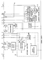
- a transformer 1 to be tested while in service includes bushings 2 and 3 through which emerge terminals 4 and 5 to which respective windings of the transformer are connected.
- Conductors 6 and 7 are connected to the terminals, and these conductors are connected to supply or utilisation networks (not shown) via respective isolators 8 and 9. For the duration of the testing procedure the isolators are temporarily opened.
- Test equipment which is temporarily connected to the conductors 6 and 7, comprises a network analyser 10 including a sweep generator 13 and a spectrum analyser 19.
- the sweep generator 13 is capable of applying to the conductor 6 a substantially sinusoidal voltage, the frequency of which is swept cyclically over a range of, say, 10kHz to 1MHz at a predetermined rate.
- the voltage applied to the conductor 6, and hence to its respective transformer winding results in the production of an output voltage at the terminal 5, as a result of the transformer impedance.
- This output voltage is fed back to the spectrum analyser 19 for analysis of its waveform.
- the result of the analysis is fed to an output device 11, which may comprise an X-Y plotter which will produce a print-out of the analysis result.
- the parameters of interest are the relative gain (or attenuation) of the transformer, and the corresponding phase shift of the signal and neither of these two parameters is difficult to measure. If the transformer is visualised as being open circuit at its bushings, the injection and measurement of these signals is not dependent upon creating exact reproductions of earlier tests. Furthermore, since the sine waves can be maintained indefinitely, there is no problem of measuring the responses accurately. This should be compared with the single shot procedure of the time domain approach.
- the present swept-frequency sinusoidal method successfully removes the requirement for exact reproduction of previous tests, and enables the data to be acquired with the desired degree of accuracy across the required frequency spectrum. Furthermore, since any change in the geometry of the transformer inevitably changes the values of the stray impedances, the resonant peaks and troughs shift in frequency. This change is immediately apparent, and the amount of shift is related to the size of physical movement.
- the problem of keeping the conductors 6 and 7 connected to the transformer 1 while making the tests complicates matters, in that the impedances applied to the transformer by those conductors, the isolators and any other equipment connected to it affect the absolute value of the applied sinusoidal voltage and its phase shift.
- the requirement is therefore to create conditions such that the measuring equipment does not 'see' anything other than the transformer. This can be accomplished by measuring the current in the conductors, and injecting secondary signals into the conductors to null these undesired currents. Under these conditions, with zero current in the conductors, the transformer 1 and the measuring equipment behave as if they were totally isolated, even though the conductors etc. are still connected.
- the measuring equipment includes a current nulling system 12.
- the current nulling system 12 includes a phase comparator 14 and an amplitude comparator 15. Each comparator receives an input from a sensor 21 on a line 16 through which the nulling signal is injected and a sensor 20 on conductors 6, 7.
- the phase comparator 14 outputs a phase error signal which drives a phase shifter 17.
- the amplitude comparator 15 outputs an amplitude error signal which drives a variable gain amplifier 18.
- the phase shifter 17 and the variable gain amplifier 18 vary the phase and amplitude of the sinusoidal signal taken from the sweep-frequency oscillator 13 to provide the nulling signal injected into conductors 6, 7 via the nulling signal line 16.
- a separate current nulling system 12 is provided for each conductor 6, 7.
- the voltage signal from the sweep generator is injected at a point A on the conductor 6, the point being physically very close to the transformer bushing terminal 4. If a voltage signal is injected by the system 12 at a point B with an amplitude and a phase equal to that at the point A, there is no current flow between A and B. This corresponds to an open circuit between these two points, and the input transformer bushing terminal 4 is therefore virtually disconnected from the external circuit. Similarly if a voltage at a point D is made equal in amplitude and phase to the voltage at a point C on the conductor 7, there is no current flow between these two points, so that the terminal 5 is effectively disconnected from the external circuit.
Landscapes
- Physics & Mathematics (AREA)
- General Physics & Mathematics (AREA)
- Measurement Of Resistance Or Impedance (AREA)
- Testing Relating To Insulation (AREA)
Applications Claiming Priority (2)
| Application Number | Priority Date | Filing Date | Title |
|---|---|---|---|
| GB868620658A GB8620658D0 (en) | 1986-08-26 | 1986-08-26 | Testing electrical equipment |
| GB8620658 | 1986-08-26 |
Publications (2)
| Publication Number | Publication Date |
|---|---|
| EP0258023A2 true EP0258023A2 (fr) | 1988-03-02 |
| EP0258023A3 EP0258023A3 (fr) | 1989-02-08 |
Family
ID=10603229
Family Applications (1)
| Application Number | Title | Priority Date | Filing Date |
|---|---|---|---|
| EP87307456A Withdrawn EP0258023A3 (fr) | 1986-08-26 | 1987-08-24 | Procédé et dispositif pour essayer un équipement électrique |
Country Status (6)
| Country | Link |
|---|---|
| US (1) | US4785233A (fr) |
| EP (1) | EP0258023A3 (fr) |
| AU (1) | AU7737987A (fr) |
| CA (1) | CA1253918A (fr) |
| GB (1) | GB8620658D0 (fr) |
| ZA (1) | ZA876313B (fr) |
Cited By (3)
| Publication number | Priority date | Publication date | Assignee | Title |
|---|---|---|---|---|
| US5373241A (en) * | 1990-10-24 | 1994-12-13 | Hendry Mechanical Works | Electric arc and radio frequency spectrum detection |
| US5477150A (en) * | 1990-10-24 | 1995-12-19 | Hendry Mechanical Works | Electric arc and radio frequency spectrum detection |
| CN103323693A (zh) * | 2012-05-15 | 2013-09-25 | 欧姆克容电子两合公司 | 用于测试电力工程测试对象的测试装置、测试系统及方法 |
Families Citing this family (5)
| Publication number | Priority date | Publication date | Assignee | Title |
|---|---|---|---|---|
| US5747992A (en) * | 1995-06-07 | 1998-05-05 | Abb Power T&D Company Inc. | Materials characterization cell for polarization spectrum and streaming electrification measurements |
| FR2860593A1 (fr) * | 2003-10-03 | 2005-04-08 | Alstom T & D Sa | Procede pour diagnostiquer un defaut sur un enroulement de transformateur |
| US8686746B2 (en) * | 2009-07-01 | 2014-04-01 | Delta Electronics, Inc. | Test apparatus and method for measuring common-mode capacitance |
| US9383413B2 (en) * | 2013-11-12 | 2016-07-05 | Siemens Demag Delaval Turbomachinery, Inc. | Method of processing recurrent surge oscillograph data to enable more precise location of generator rotor inter-turn shorts and ground faults |
| MX356684B (es) * | 2014-03-21 | 2018-06-07 | Doble Eng Company | Sistema y método para realizar diagnósticos del transformador. |
Family Cites Families (5)
| Publication number | Priority date | Publication date | Assignee | Title |
|---|---|---|---|---|
| US3904959A (en) * | 1974-08-05 | 1975-09-09 | Pacific Measurements Inc | Swept frequency measurement system |
| US4007423A (en) * | 1974-12-09 | 1977-02-08 | Intech Laboratories, Inc. | System and apparatus for electronic spectral analysis |
| CH641278A5 (de) * | 1979-10-15 | 1984-02-15 | Zumbach Electronic Ag | Vorrichtung zur messung der kapazitaet eines kabels. |
| DE3220462C1 (de) * | 1982-05-29 | 1983-12-22 | Rohde & Schwarz GmbH & Co KG, 8000 München | Spektrumanalysator |
| GB2157005A (en) * | 1984-04-06 | 1985-10-16 | Central Electr Generat Board | Detecting rotor winding faults |
-
1986
- 1986-08-26 GB GB868620658A patent/GB8620658D0/en active Pending
-
1987
- 1987-08-24 AU AU77379/87A patent/AU7737987A/en not_active Abandoned
- 1987-08-24 EP EP87307456A patent/EP0258023A3/fr not_active Withdrawn
- 1987-08-25 CA CA000545286A patent/CA1253918A/fr not_active Expired
- 1987-08-25 US US07/089,076 patent/US4785233A/en not_active Expired - Fee Related
- 1987-08-25 ZA ZA876313A patent/ZA876313B/xx unknown
Cited By (7)
| Publication number | Priority date | Publication date | Assignee | Title |
|---|---|---|---|---|
| US5373241A (en) * | 1990-10-24 | 1994-12-13 | Hendry Mechanical Works | Electric arc and radio frequency spectrum detection |
| US5477150A (en) * | 1990-10-24 | 1995-12-19 | Hendry Mechanical Works | Electric arc and radio frequency spectrum detection |
| CN103323693A (zh) * | 2012-05-15 | 2013-09-25 | 欧姆克容电子两合公司 | 用于测试电力工程测试对象的测试装置、测试系统及方法 |
| EP2664933A1 (fr) * | 2012-05-15 | 2013-11-20 | Omicron electronics GmbH | Appareil de test, système de test et procédé de test d'un échantillon technique de production d'énergie |
| KR101438670B1 (ko) | 2012-05-15 | 2014-09-05 | 오미크론 일렉트로닉스 게엠바하 | 파워 엔지니어링 테스트 객체의 테스트 장치, 테스트 시스템 및 테스트 방법 |
| AU2013205403B2 (en) * | 2012-05-15 | 2015-02-12 | Omicron Electronics Gmbh | Test device, test system and method for testing a power engineering test object |
| US9366711B2 (en) | 2012-05-15 | 2016-06-14 | Omicron Electronics Gmbh | Test device, test system and method for testing a power engineering test object |
Also Published As
| Publication number | Publication date |
|---|---|
| GB8620658D0 (en) | 1986-10-01 |
| AU7737987A (en) | 1988-03-03 |
| EP0258023A3 (fr) | 1989-02-08 |
| CA1253918A (fr) | 1989-05-09 |
| ZA876313B (en) | 1988-11-30 |
| US4785233A (en) | 1988-11-15 |
Similar Documents
| Publication | Publication Date | Title |
|---|---|---|
| KR0173490B1 (ko) | 펄스계 임피던스 측정계기 | |
| AU766993B2 (en) | Method and device for locating an insulation fault in an electric cable | |
| US5325068A (en) | Test system for measurements of insulation resistance | |
| CN108287283A (zh) | 一种工业环境下的回路阻抗的测试设备及传导抗扰度测试方法 | |
| US4425542A (en) | Method and apparatus for measuring the surface transfer impedance of a piece of shielded cable | |
| US4785233A (en) | Method and apparatus for testing electrical equipent | |
| US3803484A (en) | Method and apparatus for measuring deterioration in a shielded cable by high frequency pulse injection | |
| Subudhi et al. | Non-intrusive online time domain reflectometry technique for power cables | |
| Rostaghi-Chalaki et al. | Design of transmission line and electromagnetic field sensors for DC partial discharge analysis | |
| Passow et al. | Bandwidth and detection sensitivity analysis of integrated capacitive PD sensors for pre-molded cable joints | |
| Inwanna et al. | A locating diagnosis of partial discharge on cross-bonding ground system | |
| Mo et al. | Fault location for coaxial cables based on broadband impedance spectroscopy | |
| WO2002035248A1 (fr) | Essai de fonction de transfert de transformateur de puissance | |
| JPH1090340A (ja) | Rf回路の非破壊検査のためのシステムおよび方法 | |
| Elborki et al. | Detection and characterisation of partial discharges in transformer defect models | |
| JPH02296161A (ja) | 部分放電検出方法 | |
| Partyka et al. | UHF measurement of partial discharge on stator bars using patch antennas | |
| Black et al. | The application of the pulse discrimination system to the measurement of partial discharges in insulation under noisy conditions | |
| Grecki et al. | Validation of power transformer wideband modeling using standard sFRA method with VNA equipment | |
| Li et al. | Optimization Study of Multidimensional Computational Model for Distribution Network Cable Fault Location and Hidden Danger Warning System in Smart Grid Environment | |
| Sali | Screening efficiency of triaxial cables with optimum braided shields | |
| CN215728791U (zh) | 一种天气雷达发射系统测试平台 | |
| Dong et al. | Underground power cable diagnostics: online defect positioning | |
| Nagahama | Magnetic Measurement in Power Electronics Circuit | |
| Bozzini et al. | Fault detection and identification methods used for the LHC cryomagnets and related cabling |
Legal Events
| Date | Code | Title | Description |
|---|---|---|---|
| PUAI | Public reference made under article 153(3) epc to a published international application that has entered the european phase |
Free format text: ORIGINAL CODE: 0009012 |
|
| AK | Designated contracting states |
Kind code of ref document: A2 Designated state(s): AT BE CH DE ES FR GB GR IT LI LU NL SE |
|
| PUAL | Search report despatched |
Free format text: ORIGINAL CODE: 0009013 |
|
| AK | Designated contracting states |
Kind code of ref document: A3 Designated state(s): AT BE CH DE ES FR GB GR IT LI LU NL SE |
|
| RHK1 | Main classification (correction) |
Ipc: G01R 23/16 |
|
| STAA | Information on the status of an ep patent application or granted ep patent |
Free format text: STATUS: THE APPLICATION IS DEEMED TO BE WITHDRAWN |
|
| 18D | Application deemed to be withdrawn |
Effective date: 19890809 |
|
| RIN1 | Information on inventor provided before grant (corrected) |
Inventor name: COLEMAN, RAYMOND LESLIE |