EP0258471B1 - Verfahren und Gerät zum Messen der Antriebsfehler von Werkzeugmaschinen - Google Patents
Verfahren und Gerät zum Messen der Antriebsfehler von Werkzeugmaschinen Download PDFInfo
- Publication number
- EP0258471B1 EP0258471B1 EP19860112071 EP86112071A EP0258471B1 EP 0258471 B1 EP0258471 B1 EP 0258471B1 EP 19860112071 EP19860112071 EP 19860112071 EP 86112071 A EP86112071 A EP 86112071A EP 0258471 B1 EP0258471 B1 EP 0258471B1
- Authority
- EP
- European Patent Office
- Prior art keywords
- errors
- telescopic
- origins
- motion
- rotary joint
- Prior art date
- Legal status (The legal status is an assumption and is not a legal conclusion. Google has not performed a legal analysis and makes no representation as to the accuracy of the status listed.)
- Expired - Lifetime
Links
Images


Classifications
-
- G—PHYSICS
- G01—MEASURING; TESTING
- G01B—MEASURING LENGTH, THICKNESS OR SIMILAR LINEAR DIMENSIONS; MEASURING ANGLES; MEASURING AREAS; MEASURING IRREGULARITIES OF SURFACES OR CONTOURS
- G01B21/00—Measuring arrangements or details thereof, where the measuring technique is not covered by the other groups of this subclass, unspecified or not relevant
- G01B21/02—Measuring arrangements or details thereof, where the measuring technique is not covered by the other groups of this subclass, unspecified or not relevant for measuring length, width, or thickness
- G01B21/04—Measuring arrangements or details thereof, where the measuring technique is not covered by the other groups of this subclass, unspecified or not relevant for measuring length, width, or thickness by measuring coordinates of points
- G01B21/042—Calibration or calibration artifacts
-
- G—PHYSICS
- G05—CONTROLLING; REGULATING
- G05B—CONTROL OR REGULATING SYSTEMS IN GENERAL; FUNCTIONAL ELEMENTS OF SUCH SYSTEMS; MONITORING OR TESTING ARRANGEMENTS FOR SUCH SYSTEMS OR ELEMENTS
- G05B19/00—Program-control systems
- G05B19/02—Program-control systems electric
- G05B19/18—Numerical control [NC], i.e. automatically operating machines, in particular machine tools, e.g. in a manufacturing environment, so as to execute positioning, movement or co-ordinated operations by means of program data in numerical form
- G05B19/401—Numerical control [NC], i.e. automatically operating machines, in particular machine tools, e.g. in a manufacturing environment, so as to execute positioning, movement or co-ordinated operations by means of program data in numerical form characterised by control arrangements for measuring, e.g. calibration and initialisation, measuring workpiece for machining purposes
-
- G—PHYSICS
- G05—CONTROLLING; REGULATING
- G05B—CONTROL OR REGULATING SYSTEMS IN GENERAL; FUNCTIONAL ELEMENTS OF SUCH SYSTEMS; MONITORING OR TESTING ARRANGEMENTS FOR SUCH SYSTEMS OR ELEMENTS
- G05B2219/00—Program-control systems
- G05B2219/30—Nc systems
- G05B2219/37—Measurements
- G05B2219/37101—Vector gauge, telescopic ballbar
-
- G—PHYSICS
- G05—CONTROLLING; REGULATING
- G05B—CONTROL OR REGULATING SYSTEMS IN GENERAL; FUNCTIONAL ELEMENTS OF SUCH SYSTEMS; MONITORING OR TESTING ARRANGEMENTS FOR SUCH SYSTEMS OR ELEMENTS
- G05B2219/00—Program-control systems
- G05B2219/30—Nc systems
- G05B2219/37—Measurements
- G05B2219/37619—Characteristics of machine, deviation of movement, gauge
Definitions
- the invention relates to means for measuring motion errors of NC machine tools, using an axially telescopic bar which is coupled to rotary joints at both its ends and which comprises a built-in scale to measure its telescopic movements, wherein one rotary joint is mounted on a spindle of the NC machine tool, and one rotary joint is mounted on a table, wherein the NC machine tool is numerically controlled so that the one rotary joint takes a circular interpolation motion relative to the center of the other rotary joint, and wherein the telescopic movements of the telescopic bar are memorized and recorded to evaluate and analyse motion errors, and the pattern and the amount of deviation in relation to a datum circle are checked.
- a sampling of the values of telescopic movements can be executed periodically at a given rotational angle increment or time interval.
- a moiré fringe scale is built in the telescopic mechanism which produces signals proportional to an applied differential discplacement; those signals are subsequently carried to other electronic equipment for further treatment / display / evaluation.
- US-A-4.435.905 discloses the use of detachable extension rods of various lengths which in conjunction with a main telescopic mechanism form a telescopic means.
- a conventional method to measure motion errors of NC machine tools requires to actually machine a plate on the machine tool with a circular interpolation program, and the out-of-roundness errors of the machined plate is measured with an available means such as the out-of-roundness measuring machine as specified in JIS-B6336.
- This method requires two separate operations, machining and measuring, and takes a lot of time.
- the data obtained by this method are not accurate enough for analyzing the test results to define the origins of the errors of the machine tool because the sensitivity of the method is affected by the diameter of the cutting tool to machine a plate, as well as by the ability of an out-of-roundness measuring machine which is able to make quick responses so that fine movements of actual motions can be precisely detected.
- the measuring range of this method is restricted by the measuring range of the out-of-roundness measuring machine itself.
- the maximum diameter of a circular plate to be machined is about 400 mm even for a big machine tool having a wide working area, since the capacity of out-of-roundness measuring machines now available is about 400 mm in diameter.
- this invention provides means to measure motion errors of NC machine tools and define the origins of the detected errors by which NC machine tools can be assembled and adjusted in a shorter period of time and by which the costs of developing a new machine tool are lowered, since geometric errors can be found more easily than before, and modifications can be made at an earlier stage in developing new machines.
- the origins of said errors are defined referring to the recorded telescopic movements to prepared trace patterns of typical origins of errors, that said telescopic movements are sampled periodically at intervals of a certain period of time, that a built-in transducer detects said sampled telescopic movements and sends signals to a device to memorize said signals and to plot them on the polar coordinates in the form of a curve, and that means detect how the curve deviates from the datum circle to extract distinctive characteristics from the curve comparing them with data of typical origins for motion errors contained in a data bank and to define and display the origins for the motion errors.
- Fig.1 shows measuring members of the measuring device embodying the invention.
- Steel balls (6) and (7) are mounted on the both ends of a bar (3) which has an axial telescopic mechanism (12) in it.
- the steel ball (6) constitutes a rotary joint (4) coupled with a spherical socket (8) and a permanent magnet (10) in the spherical socket (8).
- the magnetic circuit of the permanent magnet (10) forms a closed loop through the spherical socket (8) and the steel ball (6).
- the steel ball (6) is rotatablly maintained in the spherical socket (8) when an appropriate gap is left between the permanent magnet (10) and the steel ball (6).
- the other steel ball (7) also constitutes a rotary joint (5).
- the telescopic mechanism (12) is so adjusted to allow the said bar to expand or contract in axial direction only, leaving the smallest possible play in lateral direction.
- the axial telescopic movement is detected by a displacement detector (13), which sends the signal through an output cable (14) to data processing members.
- a displacement detector 13
- One of well-known devices, such as the moiré scale and the differencial transducer is employed as said displacement detector.
- the rotary joint (4) is mounted on the machine spindle (2) utilizing a chuck (16).
- the other rotary joint (5) is mounted on the machine table (1) utilizing a fixture (15) at the same level as the rotary joint (4) appart from the steel ball (6) by R o which represents a normal distance between centers of the steel balls (5) and (6), leaving adequate allowance for the two-way axial movements of the telescopic mechanism.
- the machine is run by a pre-set program so that the XY table will take a circular interpolation motion around the center of the steel ball (6) with the radius of R o .
- the machine spindle is not rotated at that time.
- the bar (3) will rotate around the steel ball (6) with the radius of R o . If and when the motion of the XY table is not accurate, it is not able to make correct circular motion, and the value of R o changes by ⁇ R.
- the displacement ⁇ R is detected by the displacement detector (13), and the signal is sent to the data processing members through the output cable (14), where the signal is analyzed.
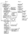
- Fig.2 The hardware of said data processing members is shown in Fig.2.
- a series of tests have been carried out employing a moiré scale as the detector (13), and the detected signals are digitized and are sent to a microcomputer (19) through an interface unit (18).
- the obtained data are processed chiefly by said microcomputer (19) which is accompanied by a CRT display (20), a floppy disc memory (21), a key board (22) and a XY plotter (23).
- Fig.3 shows a flow chart of data handling process.
- the signals sent from the detector (13) are digitized by an up-down counter (17).
- R o the normal distance between the two steel balls, shown at the begining of the test is deleted, and only displacements from R o are counted.
- the interface (18) is so adjusted that the output signals from the counter (17) are sent to the computer intermittently with a certain degree of rotational angle, every 0.1 degree for example. Though accurate signals of the rotational angle would be taken from the controller of the machine tool, it requires troublesome procedures to do so.
- NO machine tools on the market employ precise equiangular speed motion to take circular interpolation motion.
- the rond data are stored in the data memory (19) and are transferred into the polar coordinate system to make polar plots.
- the transferred data are shown on the CRT display (20) right away. All data obtained by one full turn of test are stored in the memory, and the deviations and errors in proportion to the datum circle are displayed. Such tests are carried out in one each clockwise and counter-clockwise turn to obtain bi-directional polar plots, and the motion errors of the machine tool are evaluated in total in regard to the below-mentioned items in each XY, YZ and ZX plane :
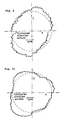
- Typical patterns of traces are shown in Fig.4, 5, 6 and 7. These typical characteristic patterns of error origins are stored in the data bank (24).
- Fig.4 represents the characteristic pattern for the extended X axis scale
- Fig.5 for periodical errors of the feed mechanism of X axis
- Fig.6 for squareness error between X and Y axes
- Fig.7 for the X axis guide way warped up in Z axis direction at its both ends.
- Fig.8 the value of ⁇ R suddenly changes at each point of X1, X2, Y1, and Y2. At such points, the direction of the movement of the XY table is reversed. The errors are apparently originated from lost motion caused by the table drive mechanism of the machine.
- the trace of Fig.9 is deviated elliptically, and is inclined against two axes, which suggests the squareness error between X and Y axes. After the error components of the lost motion and the higher harmonic vibration are eliminated, the ellipticity of the trace is 8 ⁇ m. And, the squareness error between two axes is 8 ⁇ m per 200mm since the length R o of the bar employed in said test was 200mm.
- Fig.10 shows that Y axis has the straightness error in X axis direction.
- the length R o of the bar can be adjusted as required, by changing the extension (25) of Fig.1. And, the whole working area of the large NC machine tool can be measured as accurately as the small machine tool. This method is applicable to the horizontal type machine tool also.
- the rotary joints rotatable in any direction were used. However, the purpose of this invention can be accomplished by employing rotary bearings at the both ends of the bar (3) instead of said joints as shown in Fig.11-(26).
Landscapes
- Physics & Mathematics (AREA)
- General Physics & Mathematics (AREA)
- Engineering & Computer Science (AREA)
- Human Computer Interaction (AREA)
- Manufacturing & Machinery (AREA)
- Automation & Control Theory (AREA)
- Machine Tool Sensing Apparatuses (AREA)
- Numerical Control (AREA)
- Testing Of Devices, Machine Parts, Or Other Structures Thereof (AREA)
- Measurement Of Current Or Voltage (AREA)
Claims (3)
- Vorrichtung zur Messung von Bewegungsfehlern von NC-Werkzeugmaschinen unter Verwendung einer Teleskopstange (3), die an ihren beiden Enden mit Drehgelemken (4, 5; 26) gekoppelt ist und eine eingebaute Skala (13) zur Messung ihrer Teleskopbewegungen (ΔR) aufweist, wobei ein Drehgelenk (4; 26) auf einer Spindel (2) der NC-Werkzeugmaschine montiert ist, das andere Drehgelenk (5; 26) auf einem Tisch (1) montiert ist, die NC-Werkzeugmaschine numerisch so gesteuert wird, daß das eine Drehgelenk (4; 26 bzw. 5; 26) relativ zum Zentrum des anderen Drehgelenkel (5; 26 bzw. 4; 26) eine kreisförmige Interpolationsbewegung ausführt, und wobei die Teleskopbewegungen (ΔR) der Teleskopstange (3) zur Berechnung und Analyse von Bewegungsfehlern gespeichert und aufgezeichnet werden und die Form und der Betrag der Abweichung in Bezug auf einen gegebenen Kreis geprüft werden,
dadurch gekennzeichnet, daß
Fehlerquellen unter Bezugnahme auf die aufgezeichneten Teleskopbewegungen (ΔR) zu vorgegebenen Spurformen typischer Fehlerquellen definiert werden, daß die Teleskopbewegungen (ΔR) periodisch in Intervallen einer bestimmten Zeitperiode abgetastet werden, daß ein eingebauter Wandler die abgetasteten Teleskopbewegungen (ΔR) detektiert und Signale zu einer Anordnung (19, 23) zwecks Speicherung dieser Signale und deren Ausdrucken in Polarkoordinaten in Form einer Kurve sendet und daß eine Anordnung detektiert, wie die Kurve vom gegebenen Kreis abweicht, um charakteristische Eigenschaften aus der Kurve zu entnehmen, die mit in einer Datenbank (24) enthaltenen Daten typischer Bewegungsfehlerquellen zu vergleichen und eine Anzeige der Bewegungsfehlerquellen zu definieren. - Vorrichtung nach Anspruch 1, dadurch gekennzeichnet, daß die Drehgelenke (4, 5) jeweils eine an der Stange (3) befestigte Stahlkugel (6, 7) sowie einen die Stahlkugel (6, 7) anziehenden Magneten (10, 11) in der Kugelpfanne (8, 9) umfassen.
- Vorrichtung nach Anspruch 1, dadurch gekennzeichnet, daß die Drehgelenke (26) jeweils ein Drehlager umfassen.
Priority Applications (2)
| Application Number | Priority Date | Filing Date | Title |
|---|---|---|---|
| AT86112071T ATE87380T1 (de) | 1986-09-01 | 1986-09-01 | Verfahren und geraet zum messen der antriebsfehler von werkzeugmaschinen. |
| DE19863688138 DE3688138T2 (de) | 1986-09-01 | 1986-09-01 | Verfahren und geraet zum messen der antriebsfehler von werkzeugmaschinen. |
Applications Claiming Priority (1)
| Application Number | Priority Date | Filing Date | Title |
|---|---|---|---|
| JP4611985A JPS61209857A (ja) | 1985-03-08 | 1985-03-08 | Nc工作機械の運動精度試験方法および装置 |
Publications (2)
| Publication Number | Publication Date |
|---|---|
| EP0258471A1 EP0258471A1 (de) | 1988-03-09 |
| EP0258471B1 true EP0258471B1 (de) | 1993-03-24 |
Family
ID=12738101
Family Applications (1)
| Application Number | Title | Priority Date | Filing Date |
|---|---|---|---|
| EP19860112071 Expired - Lifetime EP0258471B1 (de) | 1985-03-08 | 1986-09-01 | Verfahren und Gerät zum Messen der Antriebsfehler von Werkzeugmaschinen |
Country Status (2)
| Country | Link |
|---|---|
| EP (1) | EP0258471B1 (de) |
| JP (1) | JPS61209857A (de) |
Cited By (6)
| Publication number | Priority date | Publication date | Assignee | Title |
|---|---|---|---|---|
| US10215330B2 (en) | 2011-05-31 | 2019-02-26 | Nite Ize, Inc. | Multi-positional mount for personal electronic devices with a magnetic interface |
| US10543574B2 (en) | 2016-03-16 | 2020-01-28 | Mitsubishi Electric Corporation | Machine motion trajectory measuring apparatus |
| US11441725B2 (en) | 2011-05-31 | 2022-09-13 | Nite Ize, Inc. | Multi-positional mount for personal electronic devices with a magnetic interface |
| USD989754S1 (en) | 2020-10-20 | 2023-06-20 | Nite Ize, Inc. | Mobile device mount |
| US12047525B2 (en) | 2020-10-20 | 2024-07-23 | Nite Ize, Inc. | Squeeze device holder |
| US12510346B2 (en) | 2020-02-24 | 2025-12-30 | Renishaw Plc | Measurement method |
Families Citing this family (33)
| Publication number | Priority date | Publication date | Assignee | Title |
|---|---|---|---|---|
| JPS62222113A (ja) * | 1986-03-25 | 1987-09-30 | Kitamura Kikai Kk | Nc工作機械の精度測定装置 |
| DE3930223A1 (de) * | 1989-09-11 | 1991-03-14 | Wild Leitz Messtechnik | Pruefkoerper fuer koordinatenmessgeraete aus stabsegmenten |
| EP0429857A1 (de) * | 1989-11-27 | 1991-06-05 | Wolfgang Dr. Knapp | Verfahren zur Messung der Abweichung zwischen Bewegungen einer Maschine, die um eine Drehachse und mit zwei Translationsachsen erzeugt werden |
| DE4105433C2 (de) * | 1991-02-21 | 1994-05-19 | Heidenhain Gmbh Dr Johannes | Einrichtung zur Konturformprüfung an einer Bearbeitungs- oder Meßmaschine |
| DE69211210T2 (de) * | 1991-04-12 | 1996-10-10 | Renishaw Transducer Syst | Kalibriervorrichtung für Maschine |
| EP0526056B1 (de) * | 1991-07-27 | 1996-01-31 | Renishaw Transducer Systems Limited | Kalibrier- und Messgerät |
| DE4323992A1 (de) * | 1992-09-22 | 1994-03-24 | Bosch Gmbh Robert | Verfahren zur Überprüfung der Arbeitsgenauigkeit einer NC-Maschine |
| DE4231613A1 (de) * | 1992-09-22 | 1994-03-24 | Bosch Gmbh Robert | Verfahren zur Überprüfung der Arbeitsgenauigkeit einer NC-Maschine |
| AT398246B (de) * | 1993-06-11 | 1994-10-25 | Frank Adolf Dipl Ing Dr | Vorrichtung zur kontrolle der geometrischen und dynamischen genauigkeit eines nc-gesteuerten arbeitskopfes |
| US5533271A (en) * | 1994-08-23 | 1996-07-09 | Callaghan, Jr.; Robert P. | Long range sliding ball bar test gage |
| DE19509403A1 (de) * | 1995-03-15 | 1996-09-19 | Dreier Lasermesstechnik Gmbh | Vorrichtung zur Überprüfung der Genauigkeit einer Kreisbahn einer Arbeitsspindel |
| EP0896656A4 (de) * | 1995-11-14 | 2000-11-22 | Kam C Lau | Maschinenmontiertes ballstabsystem und verfahren zu dessen benutzung |
| KR100290298B1 (ko) * | 1999-01-08 | 2001-05-15 | 김영삼 | 다축기계의 3차원입체오차 측정장치 |
| US6850806B2 (en) | 1999-04-16 | 2005-02-01 | Siemens Energy & Automation, Inc. | Method and apparatus for determining calibration options in a motion control system |
| SE9904837L (sv) * | 1999-12-29 | 2001-02-26 | Scania Cv Ab | Förfarande och anordning vid maskinprovning |
| NL1020741C2 (nl) * | 2002-06-03 | 2003-12-08 | Stichting Tech Wetenschapp | Werkwijze en inrichting voor het vaststellen van positioneringsonnauwkeurigheden van een meerassige bewerkingsmachine. |
| US6836323B2 (en) * | 2002-10-07 | 2004-12-28 | Metronom U.S., Inc. | Spatial reference system |
| CN100453266C (zh) | 2004-08-06 | 2009-01-21 | 报国株式会社 | Nc工作机械的正圆加工方法以及正圆加工装置 |
| CN100419372C (zh) * | 2005-10-19 | 2008-09-17 | 浙江吉利汽车研究院有限公司 | 气缸盖气门环带跳动检具 |
| DE102006009422B4 (de) * | 2006-02-23 | 2011-08-18 | Dreier Lasermesstechnik GmbH, 72160 | Vorrichtung zur Überprüfung der Genauigkeit einer von einer Arbeitsspindel auszuführenden Kreisbahn |
| GB2435842A (en) * | 2006-03-09 | 2007-09-12 | Rolls Royce Plc | Ballbar equipment |
| WO2010067651A1 (ja) | 2008-12-09 | 2010-06-17 | 三菱電機株式会社 | 機械運動軌跡測定装置、数値制御工作機械および機械運動軌跡測定方法 |
| JP5448634B2 (ja) * | 2009-08-11 | 2014-03-19 | オークマ株式会社 | 機械の誤差同定方法およびプログラム |
| DE102009045688A1 (de) * | 2009-10-14 | 2011-04-28 | Dreier Lasermesstechnik Gmbh | Vorrichtung zur Überprüfung der Genauigkeit einer von einer Arbeitsspindel und/oder einem Maschinentisch auszuführenden Kreisbahn einer Werkzeugmaschine |
| CN103056721B (zh) * | 2012-12-26 | 2014-11-19 | 中国科学院长春光学精密机械与物理研究所 | 采用双读数头对绝对式钢带光栅尺的读数方法 |
| CN103495931B (zh) * | 2013-10-13 | 2015-09-02 | 吉林大学 | 一种超精密卧式抛光机床圆度测量用球杆仪连接板 |
| FR3029617B1 (fr) | 2014-12-05 | 2017-09-01 | Centre Nat Rech Scient | Procede et dispositif pour la mesure du suivi d’une trajectoire sous charge |
| CN106041643B (zh) * | 2016-07-21 | 2018-06-19 | 清华大学 | 用于双摆头五轴数控机床R-test检测的辅助工装 |
| JP6606054B2 (ja) * | 2016-12-22 | 2019-11-13 | Dmg森精機株式会社 | 工作機械の運動誤差同定方法 |
| CN107695791B (zh) * | 2017-09-26 | 2019-02-26 | 西北工业大学 | 通用转动轴与位置无关的几何误差辨识方法 |
| CN112099438B (zh) * | 2020-09-14 | 2021-10-29 | 南京简睿捷软件开发有限公司 | 一种基于电流信号的机床节能控制方法及装置 |
| CN115709398B (zh) * | 2022-11-21 | 2025-07-22 | 杭州电子科技大学 | 位移传感器和球杆仪结合的机床空间误差测量装置及方法 |
| CN120533667B (zh) * | 2025-07-10 | 2026-04-10 | 济南森峰激光科技股份有限公司 | 基于角度安装球杆仪的圆轨迹误差测量与离线补偿系统及方法 |
Citations (1)
| Publication number | Priority date | Publication date | Assignee | Title |
|---|---|---|---|---|
| US4435905A (en) * | 1982-03-15 | 1984-03-13 | The United States Of America As Represented By The United States Department Of Energy | Telescoping magnetic ball bar test gage |
Family Cites Families (1)
| Publication number | Priority date | Publication date | Assignee | Title |
|---|---|---|---|---|
| NL7711634A (nl) * | 1977-10-24 | 1979-04-26 | Philips Nv | Tachometerstelsel. |
-
1985
- 1985-03-08 JP JP4611985A patent/JPS61209857A/ja active Pending
-
1986
- 1986-09-01 EP EP19860112071 patent/EP0258471B1/de not_active Expired - Lifetime
Patent Citations (1)
| Publication number | Priority date | Publication date | Assignee | Title |
|---|---|---|---|---|
| US4435905A (en) * | 1982-03-15 | 1984-03-13 | The United States Of America As Represented By The United States Department Of Energy | Telescoping magnetic ball bar test gage |
Non-Patent Citations (3)
| Title |
|---|
| Essays for 1985 Scien.Lecture JP Society, 29.03.1985, Kakino et al. * |
| JSPE-52-07, 86-01-1193 (7.86) * |
| Simple method for testing meas. machines - J.B. Bryan, Prec. Eng. vol. 4. Nr. 2, page. 61 to 69 * |
Cited By (8)
| Publication number | Priority date | Publication date | Assignee | Title |
|---|---|---|---|---|
| US10215330B2 (en) | 2011-05-31 | 2019-02-26 | Nite Ize, Inc. | Multi-positional mount for personal electronic devices with a magnetic interface |
| US10724674B2 (en) | 2011-05-31 | 2020-07-28 | Nite Ize, Inc. | Multi-positional mount for personal electronic devices with a magnetic interface |
| US11441725B2 (en) | 2011-05-31 | 2022-09-13 | Nite Ize, Inc. | Multi-positional mount for personal electronic devices with a magnetic interface |
| US11655934B1 (en) | 2011-05-31 | 2023-05-23 | Nite Ize, Inc. | Multi-positional mount for personal electronic devices with a magnetic interface |
| US10543574B2 (en) | 2016-03-16 | 2020-01-28 | Mitsubishi Electric Corporation | Machine motion trajectory measuring apparatus |
| US12510346B2 (en) | 2020-02-24 | 2025-12-30 | Renishaw Plc | Measurement method |
| USD989754S1 (en) | 2020-10-20 | 2023-06-20 | Nite Ize, Inc. | Mobile device mount |
| US12047525B2 (en) | 2020-10-20 | 2024-07-23 | Nite Ize, Inc. | Squeeze device holder |
Also Published As
| Publication number | Publication date |
|---|---|
| JPS61209857A (ja) | 1986-09-18 |
| EP0258471A1 (de) | 1988-03-09 |
Similar Documents
| Publication | Publication Date | Title |
|---|---|---|
| EP0258471A1 (de) | Verfahren und Gerät zum Messen der Antriebsfehler von Werkzeugmaschinen | |
| Kakino et al. | The measurement of motion errors of NC machine tools and diagnosis of their origins by using telescoping magnetic ball bar method | |
| US4945501A (en) | Method for determining position within the measuring volume of a coordinate measuring machine and the like and system therefor | |
| EP0275428B2 (de) | Kalibrierungsverfahren für ein Koordinatenmessgerät und ähnliche Geräte | |
| US5111590A (en) | Measuring method of machine tool accuracy using a computer aided kinematic transducer link and its apparatus | |
| Bryan | A simple method for testing measuring machines and machine tools Part 1: Principles and applications | |
| DE60311527T3 (de) | Werkstückinspektionsverfahren und vorrichtung | |
| EP0545658B1 (de) | Automatisiertes Wartungsverfahren für digitale numerisch gesteuerte Maschinen | |
| US4562392A (en) | Stylus type touch probe system | |
| US4982504A (en) | Method for determining positional errors and for compensating for such errors, and apparatus for carrying out the method | |
| US4327493A (en) | Method and apparatus for measurement of distance between holes with parallel axes | |
| JPH0224441B2 (de) | ||
| DE3850487T2 (de) | Kontaktfreies profilierungsverfahren. | |
| CN109737884A (zh) | 一种轴类零件静动态形变量在线监测装置及方法 | |
| EP0279926B1 (de) | Positionsbestimmungsverfahren innerhalb des Messraumes eines Koordinatenmessgerätes und dergleichen und System dafür | |
| Sartori et al. | A way to improve the accuracy of a co-ordinate measuring machine | |
| Vira et al. | An extensible ball bar for evaluation of robots' positioning performance | |
| Pahk et al. | Application of microcomputer for assessing the probe lobing error and geometric errors of CMMs using commercial ring gauges | |
| DE3688138T2 (de) | Verfahren und geraet zum messen der antriebsfehler von werkzeugmaschinen. | |
| Tsutsumi et al. | New measuring method of circular movement of NC machine tools: Development of alternative method for standardization | |
| Semotiuk et al. | Measurement uncertainty analysis of different CNC machine tools measurement systems | |
| Lim et al. | A two-dimensional test body for calibration of coordinate measuring machines | |
| JPH03121751A (ja) | 機械の運動精度測定装置 | |
| JPH0654204B2 (ja) | 球体寸法測定装置 | |
| DE19818405A1 (de) | Verfahren zur Erfassung von Geometrieabweichungen wenigstens einer Achse eines Koordinatenmeßgerätes |
Legal Events
| Date | Code | Title | Description |
|---|---|---|---|
| PUAI | Public reference made under article 153(3) epc to a published international application that has entered the european phase |
Free format text: ORIGINAL CODE: 0009012 |
|
| AK | Designated contracting states |
Kind code of ref document: A1 Designated state(s): AT CH DE FR GB IT LI NL SE |
|
| 17P | Request for examination filed |
Effective date: 19880601 |
|
| 17Q | First examination report despatched |
Effective date: 19900207 |
|
| ITF | It: translation for a ep patent filed | ||
| GRAA | (expected) grant |
Free format text: ORIGINAL CODE: 0009210 |
|
| AK | Designated contracting states |
Kind code of ref document: B1 Designated state(s): AT CH DE FR GB IT LI NL SE |
|
| REF | Corresponds to: |
Ref document number: 87380 Country of ref document: AT Date of ref document: 19930415 Kind code of ref document: T |
|
| RAP4 | Party data changed (patent owner data changed or rights of a patent transferred) |
Owner name: KAKINO, YOSHIAKI, DR. |
|
| REF | Corresponds to: |
Ref document number: 3688138 Country of ref document: DE Date of ref document: 19930429 |
|
| ET | Fr: translation filed | ||
| PLBI | Opposition filed |
Free format text: ORIGINAL CODE: 0009260 |
|
| 26 | Opposition filed |
Opponent name: RENISHAW PLC Effective date: 19931210 |
|
| NLR1 | Nl: opposition has been filed with the epo |
Opponent name: RENISHAW PLC |
|
| EAL | Se: european patent in force in sweden |
Ref document number: 86112071.5 |
|
| PLBL | Opposition procedure terminated |
Free format text: ORIGINAL CODE: EPIDOS OPPC |
|
| PLBM | Termination of opposition procedure: date of legal effect published |
Free format text: ORIGINAL CODE: 0009276 |
|
| STAA | Information on the status of an ep patent application or granted ep patent |
Free format text: STATUS: OPPOSITION PROCEDURE CLOSED |
|
| 27C | Opposition proceedings terminated |
Effective date: 19970613 |
|
| NLR2 | Nl: decision of opposition | ||
| REG | Reference to a national code |
Ref country code: GB Ref legal event code: IF02 |
|
| PGFP | Annual fee paid to national office [announced via postgrant information from national office to epo] |
Ref country code: GB Payment date: 20040823 Year of fee payment: 19 |
|
| PGFP | Annual fee paid to national office [announced via postgrant information from national office to epo] |
Ref country code: DE Payment date: 20040907 Year of fee payment: 19 |
|
| PGFP | Annual fee paid to national office [announced via postgrant information from national office to epo] |
Ref country code: SE Payment date: 20040909 Year of fee payment: 19 Ref country code: NL Payment date: 20040909 Year of fee payment: 19 Ref country code: CH Payment date: 20040909 Year of fee payment: 19 |
|
| PGFP | Annual fee paid to national office [announced via postgrant information from national office to epo] |
Ref country code: FR Payment date: 20040910 Year of fee payment: 19 Ref country code: AT Payment date: 20040910 Year of fee payment: 19 |
|
| PG25 | Lapsed in a contracting state [announced via postgrant information from national office to epo] |
Ref country code: IT Free format text: LAPSE BECAUSE OF NON-PAYMENT OF DUE FEES;WARNING: LAPSES OF ITALIAN PATENTS WITH EFFECTIVE DATE BEFORE 2007 MAY HAVE OCCURRED AT ANY TIME BEFORE 2007. THE CORRECT EFFECTIVE DATE MAY BE DIFFERENT FROM THE ONE RECORDED. Effective date: 20050901 Ref country code: GB Free format text: LAPSE BECAUSE OF NON-PAYMENT OF DUE FEES Effective date: 20050901 Ref country code: AT Free format text: LAPSE BECAUSE OF NON-PAYMENT OF DUE FEES Effective date: 20050901 |
|
| PG25 | Lapsed in a contracting state [announced via postgrant information from national office to epo] |
Ref country code: SE Free format text: LAPSE BECAUSE OF NON-PAYMENT OF DUE FEES Effective date: 20050902 |
|
| PG25 | Lapsed in a contracting state [announced via postgrant information from national office to epo] |
Ref country code: LI Free format text: LAPSE BECAUSE OF NON-PAYMENT OF DUE FEES Effective date: 20050930 Ref country code: CH Free format text: LAPSE BECAUSE OF NON-PAYMENT OF DUE FEES Effective date: 20050930 |
|
| PG25 | Lapsed in a contracting state [announced via postgrant information from national office to epo] |
Ref country code: NL Free format text: LAPSE BECAUSE OF NON-PAYMENT OF DUE FEES Effective date: 20060401 Ref country code: DE Free format text: LAPSE BECAUSE OF NON-PAYMENT OF DUE FEES Effective date: 20060401 |
|
| REG | Reference to a national code |
Ref country code: CH Ref legal event code: PL |
|
| EUG | Se: european patent has lapsed | ||
| GBPC | Gb: european patent ceased through non-payment of renewal fee |
Effective date: 20050901 |
|
| PG25 | Lapsed in a contracting state [announced via postgrant information from national office to epo] |
Ref country code: FR Free format text: LAPSE BECAUSE OF NON-PAYMENT OF DUE FEES Effective date: 20060531 |
|
| NLV4 | Nl: lapsed or anulled due to non-payment of the annual fee |
Effective date: 20060401 |
|
| REG | Reference to a national code |
Ref country code: FR Ref legal event code: ST Effective date: 20060531 |