EP0258522A1 - Unité de transmission linéaire - Google Patents
Unité de transmission linéaire Download PDFInfo
- Publication number
- EP0258522A1 EP0258522A1 EP87102402A EP87102402A EP0258522A1 EP 0258522 A1 EP0258522 A1 EP 0258522A1 EP 87102402 A EP87102402 A EP 87102402A EP 87102402 A EP87102402 A EP 87102402A EP 0258522 A1 EP0258522 A1 EP 0258522A1
- Authority
- EP
- European Patent Office
- Prior art keywords
- drive unit
- housing
- linear drive
- drive
- linear
- Prior art date
- Legal status (The legal status is an assumption and is not a legal conclusion. Google has not performed a legal analysis and makes no representation as to the accuracy of the status listed.)
- Granted
Links
- 238000006243 chemical reaction Methods 0.000 claims abstract description 28
- 230000005540 biological transmission Effects 0.000 claims abstract description 4
- 239000000314 lubricant Substances 0.000 claims description 6
- 230000015572 biosynthetic process Effects 0.000 claims description 3
- 238000001746 injection moulding Methods 0.000 claims description 2
- 230000002093 peripheral effect Effects 0.000 claims 1
- 229910000831 Steel Inorganic materials 0.000 description 9
- 239000010959 steel Substances 0.000 description 9
- 239000004519 grease Substances 0.000 description 7
- 230000001419 dependent effect Effects 0.000 description 6
- 230000004323 axial length Effects 0.000 description 5
- 230000000295 complement effect Effects 0.000 description 3
- 238000010276 construction Methods 0.000 description 3
- 238000006073 displacement reaction Methods 0.000 description 3
- 230000003134 recirculating effect Effects 0.000 description 3
- 239000000969 carrier Substances 0.000 description 2
- 230000002349 favourable effect Effects 0.000 description 2
- 238000004904 shortening Methods 0.000 description 2
- 239000000243 solution Substances 0.000 description 2
- 238000004804 winding Methods 0.000 description 2
- 229910000906 Bronze Inorganic materials 0.000 description 1
- 230000002411 adverse Effects 0.000 description 1
- 239000010974 bronze Substances 0.000 description 1
- 230000006835 compression Effects 0.000 description 1
- 238000007906 compression Methods 0.000 description 1
- KUNSUQLRTQLHQQ-UHFFFAOYSA-N copper tin Chemical compound [Cu].[Sn] KUNSUQLRTQLHQQ-UHFFFAOYSA-N 0.000 description 1
- 230000007423 decrease Effects 0.000 description 1
- 230000018109 developmental process Effects 0.000 description 1
- 230000000694 effects Effects 0.000 description 1
- 238000009415 formwork Methods 0.000 description 1
- 238000002347 injection Methods 0.000 description 1
- 239000007924 injection Substances 0.000 description 1
- 238000005461 lubrication Methods 0.000 description 1
- 238000005096 rolling process Methods 0.000 description 1
- 230000001360 synchronised effect Effects 0.000 description 1
- 230000007704 transition Effects 0.000 description 1
Images


Classifications
-
- F—MECHANICAL ENGINEERING; LIGHTING; HEATING; WEAPONS; BLASTING
- F16—ENGINEERING ELEMENTS AND UNITS; GENERAL MEASURES FOR PRODUCING AND MAINTAINING EFFECTIVE FUNCTIONING OF MACHINES OR INSTALLATIONS; THERMAL INSULATION IN GENERAL
- F16H—GEARING
- F16H25/00—Gearings comprising primarily only cams, cam-followers and screw-and-nut mechanisms
- F16H25/18—Gearings comprising primarily only cams, cam-followers and screw-and-nut mechanisms for conveying or interconverting oscillating or reciprocating motions
- F16H25/20—Screw mechanisms
- F16H25/22—Screw mechanisms with balls, rollers, or similar members between the co-operating parts; Elements essential to the use of such members
- F16H25/2247—Screw mechanisms with balls, rollers, or similar members between the co-operating parts; Elements essential to the use of such members with rollers
- F16H25/2252—Planetary rollers between nut and screw
-
- H—ELECTRICITY
- H02—GENERATION; CONVERSION OR DISTRIBUTION OF ELECTRIC POWER
- H02K—DYNAMO-ELECTRIC MACHINES
- H02K7/00—Arrangements for handling mechanical energy structurally associated with dynamo-electric machines, e.g. structural association with mechanical driving motors or auxiliary dynamo-electric machines
- H02K7/06—Means for converting reciprocating motion into rotary motion or vice versa
-
- F—MECHANICAL ENGINEERING; LIGHTING; HEATING; WEAPONS; BLASTING
- F16—ENGINEERING ELEMENTS AND UNITS; GENERAL MEASURES FOR PRODUCING AND MAINTAINING EFFECTIVE FUNCTIONING OF MACHINES OR INSTALLATIONS; THERMAL INSULATION IN GENERAL
- F16H—GEARING
- F16H25/00—Gearings comprising primarily only cams, cam-followers and screw-and-nut mechanisms
- F16H25/18—Gearings comprising primarily only cams, cam-followers and screw-and-nut mechanisms for conveying or interconverting oscillating or reciprocating motions
- F16H25/20—Screw mechanisms
- F16H2025/2062—Arrangements for driving the actuator
- F16H2025/2075—Coaxial drive motors
Definitions
- Linear drive units are known in a whole series of designs, the most basic, recurring functional components being a drive motor, a linearly drivable output rod, a conversion drive connected to the motor, which converts the rotary movement into linear movement of the output rod, and often a reduction gear between the Engine and the implementation drive can look at.
- a frequently chosen form of implementation drive is a nut-screw drive.
- DE-C-855 785 shows several options for the constructive design of the conversion drive, including an embodiment in which a rotatable drive body that is connected to the motor in drive connection has on its circumference a plurality of revolving bodies with a circumferential groove profile that has an internal thread of the output rods -Hollow area are in thread-like engagement.
- a rotatable drive body that is connected to the motor in drive connection has on its circumference a plurality of revolving bodies with a circumferential groove profile that has an internal thread of the output rods -Hollow area are in thread-like engagement.
- the object of the invention according to claim 1 is based on the object of providing a linear drive unit which is structurally suitable for the generation of high linear forces and which has a more load-bearing design of the conversion drive.
- the storage of the rotating bodies which are generally of small diameter, is practically kept free of axial forces, and the linear forces supplied by the linear drive unit are introduced into the driving body via the engagement of the rotating body trough profiling and the driving body trough profiling with a selectable axial length.
- the meshing engagement between the drive body and the rotating bodies ensures that no slipping occurs between the driving body and the rotating bodies.
- the channel profiles of the drive body and the rotating body are preferably designed as threads, the thread pitch direction of the rotating body being opposite to the thread pitch direction of the driving body, i.e. left-hand thread on the driving body and right-hand thread on the rotating body or vice versa.
- groove profile rubbed body in connection with the T, the turning bodies, and the hollow portion of the output rod is chosen to both a respective group of parallel, circular, returning contained grooves axially next to each other as well as a helical To include gutter course according to a thread. If the channel profiles in the drive body and in the rotating bodies are designed in accordance with the first-mentioned type, the channel profiles in the output rod must be thread-like in order to achieve the intended conversion of rotational movement into linear movement.
- the channel profiling in the output rod can either be designed according to the first-mentioned type or also thread-like, with both a thread pitch direction corresponding to the thread pitch direction of the rotating body (synchronous operation) and a thread pitch direction opposite Thread pitch direction of the rotating body (counter-rotating operation) comes into consideration.
- the thread of the drive body must have multiple threads corresponding to the integer multiples mentioned, cf. Claim 3.
- Particularly preferred are drive bodies with two-start thread, three-start thread, four-start thread, five-start thread or six-start thread, interacting with rotating bodies with single-start thread.
- “Two-start thread” means, for example, that a thread under consideration after 360 ° around the drive body does not open into the adjacent thread, but into the thread after next. The same applies to threads that are three-thread, four-thread, etc.
- the combination of the drive body with a multi-start thread correspondingly smaller circular bodies with a single-start thread and an internal thread in the hollow area of the output rod, which is designed with multiple threads according to the multi-start of the drive body thread and with the same thread pitch direction as the thread of the round body.
- the circulating bodies are preferably mounted in two rings which are rotatable relative to the drive body. This keeps the circulating body at the desired mutual distance in the circumferential direction.
- the rings are not highly stressed components because - as already indicated - the revolving bodies exert practically no axial forces on their bearings and are supported in the radial direction between the output rod and the drive body.
- the space between the housing and the hollow area of the output rod contains a lubricant, in particular grease, and axial lubricant passage channels are provided in the drive body, so that the lubricant during the linear movements of the output rod from one side of the drive body to the other Side and back.
- lubricant passage channels can also be formed by the spaces between the circulating bodies. The lubrication increases the service life considerably.
- connection area in order to be able to conveniently connect the linear drive unit at both ends to a base or an object to be driven linearly, it advantageously has a fastening area or connection area at each end. It is preferred to provide these connection areas in the form of fastening parts which are provided or attached to the one axial end of the housing or to the axial end of the output rod facing away from the housing. It is preferably attached by Screwing, injection molding of a plastic fastening part or by attachment by means of a cone ring, the latter possibility, which is particularly suitable for the transmission of high forces and torques, being particularly preferred, in particular on the one axial end of the housing, where reaction torques are also to be transmitted.
- a reduction gear between the motor and the drive body is preferably provided in many cases.
- Single-stage or multi-stage planetary reduction gears which take up little space and can be built in several stages to save space, are particularly suitable.
- the reduction gear is preferably accommodated in the housing, which also contains the motor.
- the linear drive unit according to the invention is also suitable, particularly because of the large diameter of the output rod, for larger linear movement distances or strokes. It is possible in a development of the invention to make the stroke particularly large in a simple manner by making the housing longer than would be necessary to accommodate the motor and possibly the reduction gear itself, for example by attaching a cylindrical housing extension part. In this way, linear drive units with different strokes can also be conveniently manufactured without having to change anything else on the overall construction.
- At least one limit switch integrated in the linear drive unit advantageously a limit switch for each end position in each linear movement direction, which limit switch can be actuated by a linearly movable actuating part.
- a particularly space-saving and happy construction for this is that a transmission shaft is coupled to the shaft driving the drive body, which is fed back through the hollow rotor of the motor and possibly the reduction gear and on the other axial side of the motor as a threaded spindle with a traveling nut as a limit switch actuating part is engaged. Since you can choose the thread pitch when pairing the limit switch-threaded spindle / limit switch-traveling nut differently than when pairing the drive body / output rod, you can manage with little space for the limit switch.
- a shutdown of the drive motor which is dependent on the linear force of the output rod.
- a preferred possibility for this is to make two parts of the linear drive unit lying in the force flow movable relative to one another against spring force. Over one, forward. longitudinal forces of the output rod, which are preferably adjustable, lie as an axial evasive movement of one of the two parts which are movable relative to one another, and this evasive movement can be used to actuate a switch or a switch per linear direction.
- a force-dependent shutdown is independent of an output rod position-dependent (end) shutdown, so that limit switch adjustments no longer have any influence and the function of a safety shutdown is also provided in the entire range of the stroke of the output rod.
- the power-operated shutdown also contains the function of the limit switch when you switch into the End positions of the output rod move against a corresponding resistance or stop.
- slipping between the circulating bodies and the output rod which can theoretically occur in extreme cases, no longer has an adverse effect on an adjustment of the relationship between the limit switches and the output rod, so that there is a precise shutdown regardless of any slipping.
- a structurally particularly favorable solution of the power-operated shutdown is that a fastening part is provided at one axial end of the linear drive unit, which is held rotatably relative to the housing and axially displaceable through an end wall opening into the interior of the linear drive unit, that a spring unit between one at the Fastening part formed shoulder and an abutment is provided in the linear drive unit, and that the fastening part is provided with an actuating part which actuates the at least one switch when the fastening part is displaced sufficiently in the end wall opening.
- a common spring unit is preferably provided for both axial evasive movement directions of the fastening part, which is supported on the side opposite the shoulder radially inward against a further shoulder of the fastening part and radially further outward against the abutment and is supported radially outside the first shoulder against a further abutment .
- the (first-mentioned) shoulder can be formed particularly favorably by a nut screwed onto the fastening part, by tightening the spring unit a prestress can be given.
- the linear drive unit it is preferred for certain applications to equip the linear drive unit as a device with two, in opposite or in the same direction, movable output rods and to hold the linear drive unit in the center.
- a particularly preferred design One possibility for this is to couple an intermediate shaft with the shaft driving the first drive body, which leads through the hollow rotor of the motor and possibly the reduction gear to the other axial side of the motor and carries a second drive body there which, with the second output rod, carries a second conversion drive forms.
- the second conversion drive and the second output rod are preferably designed analogously, as described above for the first conversion drive and the first output rod.
- the circumferential channel profiling or the thread on the inner circumference of the output rod is provided on at least two sleeves placed axially against one another, which are welded in a common, pushed-on tube. It has been found that internal threads of greater length or with a greater ratio of length to diameter are relatively difficult or expensive to produce. It is therefore preferred to produce such relatively long internal threads by producing shorter, internally threaded sleeves, screwing these sleeves together on a spindle-like, externally threaded part with a smooth thread transition, then pushing a precisely fitting, internally smooth outer tube over the sleeve arrangement , then welded the sleeves to the outer tube and finally unscrewed the thistle-like inner part.
- the hollow area of the output rod is a steel tube provided with an internal thread.
- a particularly inexpensive way of producing the internal thread is thread whirling, which is known per se.
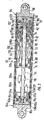
- the linear drive unit 52 shown in FIG. 1 essentially consists of an outer cylindrical housing 54 with a fastening part 56 fastened to it on the left and arranged therein an electric motor 58 and a three-stage planetary reduction gear 60, a conversion drive 62 to the right of the housing 54, and an output rod 64 with fastener 66 attached to the right.
- the housing 54 consists primarily of a tube 68 to which the fastening part 56 is fastened on the left and an end wall 70 is fastened on the right in the manner described in more detail below.
- the stator 72 of the electric motor 58 which has windings, is fastened in the tube 68, a little to the left of the center in the drawing.
- round mounting parts 74 are fastened on the inside in the tube 68, each holding a ball bearing 76 on the inside for mounting the rotor 78 of the electric motor 58.
- the rotor 78 has a hollow shaft 80, the right end region of which is toothed as a pinion 82.
- the pinion 82 meshes with planet gears 84, which in turn mesh outside with a stationary ring gear toothing 86.
- the planet gears 84 are rotatably mounted on a planet carrier 88 which in turn is rotatable.
- the right end region of this planet carrier 88 is toothed as a pinion.
- This is followed by two further planetary gear stages, which are constructed analogously to the first planetary stage described above, but the third planet gear carrier 88 is extended to the right out of the housing 54 and thus forms a drive shaft 90 for a drive body or a drive pulley 92.
- the planet gears 84 of all three planetary gears mesh on the outside with the ring gear toothing 86, which is partly in an axial extension of the right holding part 74, which projects to the right, and partly in an axially adjoining, wide one Ren bracket part 94 is formed.
- the first and second planet gear carriers are rotatably mounted on an intermediate shaft 96, which will be described in more detail below.
- the third planet gear carrier 88 or the drive shaft 90 is mounted in a radial sliding manner in the mounting part 94 and the end wall 70, an axial roller bearing being interposed between the mounting part 94.
- the drive pulley 92 On the right end of the drive shaft 90, the drive pulley 92 is rotatably and axially held.
- the drive pulley 92 is located axially to the right of the end wall 70 and is supported against the end wall 70 by means of an axial ball bearing 98.
- the outer diameter of the drive pulley 92 is somewhat larger than the outer diameter of the tube 68 and there has a thread 100 with a semicircular-convex thread profile.
- the external thread 100 of the drive pulley 92 meshes with a suitable internal thread 102 on the inner circumference of a hollow area 104 of the output rod 64.
- the internal thread 102 extends almost over the entire length of the hollow area 104, and the hollow area 104, starting from the left, takes up almost the entire length of the Output rod 64 a. On the right, only the fastening part 66 is connected.
- the internal thread 102 is produced in that essentially hollow cylindrical plastic 108 has been injected into the inside of a steel tube 106 provided with a fine thread, similar to the shape of the internal thread 102.
- the fine thread described holds the plastic part 108, in particular axially.
- radial grub screws or pins could also be provided.
- a plastic ring 110 is screwed in and secured, the inner diameter of which can slide in the axial direction on the outer circumference of the housing tube 68. If necessary, the ring 110 can have a separate seal on the inside.
- the ring 110 In the drawn, fully contracted state of the L inearantriebsaku 52, the ring 110 is located approximately at the left end of the housing 54.
- the output rod 64 can be moved out relative to the housing 54, is moved to the ring 110 to close to the drive disk 92nd
- the stroke of the linear drive unit 52 is only slightly less than the length of the steel tube 106.
- the intermediate shaft 96 which has already been briefly mentioned, is received with its right end region in a corresponding central blind bore 112 of the drive shaft 90 which is open to the left and is fixed in a rotationally fixed manner.
- the intermediate shaft 96 extends to the left through the reduction gear 60 and the hollow shaft 80 of the electric motor 58.
- the left end region of the intermediate shaft 96 is provided with a thread 114 on which a traveling nut 116 moves axially when the intermediate shaft 96 rotates.
- the W other nut 116 is non-rotatably in the left support member 74 but axially displaceably supported.
- the traveling nut 116 has two switching cams 118 on the outside, each of which interacts with a limit switch 120 fastened to the left holding part 74. In this way, the electric motor 58 is switched off both when the completely collapsed state is reached and when the completely separated state of the linear drive unit 52 is reached.
- the left fastening part 56 in the form of a fastening eye is fastened to the left end of the housing 54 in that screws 120 are screwed from the outside in the axial direction into an outer conical inner ring 122 and that between the inner ring 122 and the fastening part 56 an internally complementary conical, slotted intermediate ring 124 is interposed, which is pressed radially outward against the end region of the tube 68 by tightening the screws 120.
- Forces in the pulling direction of the fixing part lead 56 as a result to an increase of the clamping force of the intermediate ring 124 in the housing tube 68.
- At the right end of the housing 54 is the ex B chlußwand 70 in quite an analogous manner fixed to the housing pipe 68, said further holding part 94 as the inner ring for the screws serves.
- the right fastening part 66 could be fastened in an analogous manner to the right on the steel tube 106 of the output rod 64.
- the fastening part 66 is injection molded onto the right end region of the steel tube 106, in one piece with the plastic threaded part 108.
- the right fastening part 66 is therefore made of plastic, and a metallic tie rod bracket can also be injected.
- axially continuous passage channels 126 can be seen in the drive pulley 92. Between the inner circumference of the plastic threaded part 108 and the outer circumference of the housing tube 68 there is a space which contains grease. If the output rod 64 is extended to the right, starting from the drawn state, this space is reduced due to the shortening of the axial length, and grease contained can pass through the passage channels 126 to the simultaneously enlarging space to the right of the drive pulley 92 and inside the cavity 104 the output rod 64 arrive. When the linear drive unit 52 is moved together, this grease displacement takes place in the opposite direction.
- the drive pulley 92 has an axial width that is matched to the possible linear force of the linear drive unit 52.
- the electric motor 58 When the electric motor 58 is switched on, its rotor shaft 80 drives into the three-stage planetary reduction gear 60. From there, the rotating force occurs flow over the drive shaft 90 to the rotating drive pulley 92, which rotates at a much lower speed than the electric motor 58. At the engagement of the threads 100 and 102, the conversion of the rotating movement of the drive pulley 92 into the linear movement of the driven rod 64 takes place.
- the hollow region 104 of the driven rod 64 has a large diameter and engages with a part which is dependent on the extent to which the linear drive unit 52 moves apart its length over the housing 54 and is supported at its open end on the outer circumference of the housing 54.
- the housing tube 68 can be extended by axially attaching a housing extension tube, for example by means of a screw intermediate ring, the fastening part 56 then of course then having to be attached to the free end of the housing extension tube.
- the hollow area 104 of the output rod 64 can then be correspondingly longer.
- the linear drive unit 52 shown in FIG. 2 essentially consists of an outer cylindrical housing 54 with an electric motor 58 arranged therein and a three-stage planetary reduction gear 60, a first conversion drive 62 to the right of the housing 54, a second conversion drive 64a to the left of the housing 54 , a first output rod 64 with the right-affixed fixing part 66 and a second output rod 64a with the left-affixed fIXING l P-part 66a.
- the housing 54 consists primarily of a tube 68 which is axially composed of two tube parts by means of an intermediate screw ring 69 and to which an end wall 70 and 70a is fastened on the right and left in the manner described in more detail below.
- a piece to the right of the center the stator 72 having the windings of the electric motor 58 is fastened.
- round mounting parts 74 are fastened on the inside in the tube 68, each holding a ball bearing 76 on the inside for mounting the rotor 78 of the electric motor 58.
- the rotor 78 has a hollow shaft 80, the right end region of which is toothed as a pinion 82.
- the pinion 82 meshes with planet gears 84, which in turn mesh outside with a stationary ring gear toothing 86.
- the planet gears 84 are rotatably mounted on a planet carrier 88 which in turn is rotatable.
- the right end region of this planet carrier 88 is toothed as a pinion.
- This is followed by two further planetary gear stages, which are constructed analogously to the first planetary stage described above, but the third planet carrier 88 is extended to the right out of the housing 54 and thus forms a drive shaft 90 for a drive pulley 92.
- the Planentenrä of the 84 of all three planetary stages mesh on the outside with the ring gear toothing 86, which is formed partly in an axial extension of the right holding part 74 projecting to the right and partly in an axially adjoining further holding part 94.
- the first and second planet gear carriers are rotatably mounted on an intermediate shaft 96, which will be described in more detail below.
- the third planet gear carrier 88 or the drive shaft 90 is radially slidingly supported in the mounting part 94 and the right end wall 70, an axial roller bearing being interposed between the mounting part 94.
- the right T is rubbed disc 92 rotatably and arranged axially.
- the drive disc 92 is located axially adjacent to the right of the right end wall 70 and is supported by an A xialkugellagers 98 against the end wall 70 from.
- the outer diameter of the drive pulley 92 is somewhat larger than the outer diameter of the tube 68 and there has a thread 100 with a semicircular-convex thread profile.
- the external thread 100 of the drive wheel 92 meshes with a matching internal thread 102 on the inner circumference e i n it hollow portion 104 of the output rod 64.
- the female screw 102 extends almost over the entire length of the hollow portion 104, and the hollow portion 104 decreases, starting from the left, nearly entire length of the output rod 64. On the right, only the fastening part 66 is connected.
- the internal thread 102 is produced in that essentially hollow cylindrical plastic 108 has been injected into the inside of a steel tube 106 provided with a fine thread, similar to the shape of the internal thread 102.
- the fine thread described holds the plastic part 108, in particular axially.
- radial grub screws or pins could also be provided.
- a first plastic ring 110 is screwed in and secured, the inside diameter of which is on the outside circumference of the housing tube 68 can slide in the axial direction. If necessary, the ring 110 can have a separate seal on the inside.
- the left or second output rod 64a and the left or second conversion drive 62a are constructed in a mirror-image manner, with the exception of the drive of the second drive pulley 92a described below.
- the intermediate shaft 96 which has already been briefly mentioned, is received with its right end region in a corresponding central blind bore 112 of the drive shaft 90 which is open to the left and is fixed in a rotationally fixed manner.
- the intermediate shaft 96 extends to the left through the reduction gear 60 and the hollow shaft 80 of the electric motor 58.
- a portion of the intermediate shaft 96 to the left of the left holding part 74 is provided with a thread 114, on which two traveling nuts 116 each have a limit switch 120 when the Axially move intermediate shaft 96.
- the limit switches 120 are secured against rotation but axially displaceably supported in the housing 54 and in the end positions abut the left holding part 74 or a left inner ring 122a described in more detail below on the left end region of the housing 54. In this way, the electric motor 58 both when reaching the completely converged State as well as when the completely separated state of the linear drive unit 52 is reached.
- the left end wall 70a is fastened to the left end of the housing 54 in that screws 120a are screwed from the outside in the axial direction into the outer conical, left inner ring 122a and that between the inner ring 122a and the end wall 70a an internally complementary conical, slotted left intermediate ring 124a is interposed, which is pressed radially outward against the left end region of the tube 68 by tightening the screws 120a.
- the right end wall 70 is fastened in an analogous manner to the housing tube 68.
- the intermediate shaft 96 passes through the left inner ring 122a and the left end wall 70a, in which it is mounted with a roller bearing.
- the second drive pulley 92a is fastened on the left end region of the intermediate shaft 96, analogously to the first drive pulley 92 on the drive shaft 90.
- the fastening parts 66, 66a are injection-molded onto the right end region of the right steel tube 106 or the left end region of the left steel tube 106a, in each case in one piece with the plastic threaded part 108, 108a.
- the fastening parts 66, 66a thus consist of plastic, and a metallic tie rod bracket can be injected in each case.
- axially continuous passage channels 126 can be seen in the drive pulley 92.
- the grease contains. If the output rod 64 is extended to the right, starting from the drawn state, this space is reduced due to the shortening of the axial length, and contained grease can pass through the passages 126 into the simultaneously enlarging space to the right of the drive pulley 92 and inside the cavity 104 the output rod 64 arrive.
- the drive pulley 92 has an axial width that is matched to the possible linear force of the linear drive unit 52. The same applies to the second drive pulley 92a with passage channels 126a.
- the hollow area 104 of the respective output rod 64 or 64a has a large diameter and, with a part of its length depending on the extent to which the linear drive unit 52 moves apart, extends over the housing 54 and is supported at its open end on the outer circumference of the housing 54.
- the linear drive unit is fastened to a base by a central fastening part, not shown, which is fastened to the housing 54.
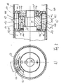
- FIG. 3 shows a preferred, more complicated implementation drive, which can be thought of as replacing the implementation drive shown in FIGS. 1 and 2.
- Electric motor 58 and reduction gear 60 are only indicated schematically.
- the drive shaft 90 led out of the reduction gear 60 carries a drive body 92 in a rotationally fixed manner, which essentially consists of a central part 150, an axially left ring 152 and an axially right ring 154.
- the central part 150 and the right ring 154 are tensioned to the left against a shoulder of the drive shaft 90 by a nut 156 screwed onto the end of the drive shaft 90.
- the left ring 152 is supported on the left against the thrust bearing 98, which in turn is supported on the left against the end wall 70.
- the parts 150, 152, 154 are secured against mutual rotation by axial pins 158.
- the outer circumference of the middle part 150 is provided with a channel profile 160 in the form of a six-start left-hand thread.
- the two rings 152, 154 are provided on their outer circumference with a spur gear-like toothing 162, the pitch circle of the thread 160 and the pitch circles of the toothing 162 coinciding with one another.
- a total of twelve circulating bodies 166 are arranged along a circular circumference, each of which is mounted with its axial ends in two rings 168.
- the Rings 168 each have a circular inner projection 170, which runs to fix the rings 168 axially in position between the bearing rings of the axial bearing 98 or in a circular outer groove between the nut 156 and a further screwed nut 156 ', both of which are round on the outside.
- the circulating bodies 166 are provided on the outer circumference for the entire axial length in each case with a channel profile 172 in the form of a single-thread right-hand thread.
- the revolving bodies 166 are each provided in their two axial end regions with a spur gear-like toothing 174 which is simply incorporated in addition to the thread.
- the pitch circles of the thread 172 and the toothing 174 match.
- the toothing 174 mesh with the toothing 162 of the rings 152, 154.
- Radially on the outside, the thread 172 is in engagement with the thread 164 of the output rod 64.
- the central region of the thread 172 engages radially on the inside with the thread 160 of the central part 150.
- the revolving bodies 166 have a pitch circle diameter which is one sixth of the pitch circle diameter of the drive body 92.
- the rotating bodies 166 rotate at a speed about its own axis 176 which is six times the speed of the drive body 92. Since there is an engagement between the one-way right-hand thread and a six-thread left-hand thread between the rotating bodies 166 and the drive body 92, the rotating bodies 166 remain as planets, so to speak, when the driving body 92 rotates and the rotating bodies 166 rotate about their own axis and the axes 176 of the driving bodies 166 move around around the drive body 92 axially in its place. As a result of the rotation of the rotating bodies 166, an axial linear driving force is exerted on the output rod 64.
- All mutual interference between the drive body 92, the Recirculating bodies 166 and the thread 164 of the output rod 64 are of a rolling rather than a sliding nature and are essentially point-shaped or linear in the teeth.
- the axial width of the T rubbed body 92 and the revolving member 166 can be placed on the occurring loads.
- FIG. 4 shows a force-dependent shutdown 180 of a linear drive unit, which can be imagined installed at the axially left end of the linear drive unit shown in FIG. 1, in addition to or instead of the position-dependent limit shutdown present there.
- a fastening part 198 which has a connection eye 200 in its axially left end region, has a region 202 with a hexagonal cross section to the right of the connection eye, which region is passed through the hexagonal opening 194 of the sleeve 192. That follows on the right with a shoulder 204 a cylindrical region 206 of the fastening part 198 with a slightly smaller outer diameter. To the right of this is a threaded area 208, onto which an externally round nut 210 is screwed. The round outer circumference of the nut 210 is slidably received in a corresponding inner bore of the intermediate ring 286.
- the intermediate ring 186 has a shoulder 214 pointing to the left on its inner circumference.
- a spring unit 216 in the form of a preloaded plate spring assembly is provided, which, when the linear unit is in the idle state shown, is located on the right radially outside on the shoulder 214 of the intermediate ring 186, on the right radially further inside on the left end face 212 of the nut 210, on the left radially inside on the shoulder 204 of the fastening part 198 and on the left radially further out on the sleeve 192.
- the elements 204 and 212 thus form shoulders of the fastening part 198 and the elements 214 and 192 abutments assigned to the housing 54.
- An actuating part 220 is fastened to a cylindrical, axially rightward-projecting extension 218 of the fastening part 198, which has a left-cylindrical, hollow-cylindrical extension 222 for fastening to the extension 218 and to the right essentially has the shape of an upright rectangular plate, the plane of which is perpendicular to the longitudinal axis of the fastening part 198 and the linear drive unit.
- a first microswitch 226 is located to the left of the plate 224, and a second microswitch 228 is located to the right of the plate 224.
- the axial positions of the microswitches 226, 228 can be adjusted by adjusting spindles 230, which are axially by the intermediate ring 186 and Lead end wall 182 to the outside, are adjusted.
- the spring unit 216 compresses between the nut 210 and the sleeve 192, the hexagonal region 202 of the fastening part 198 migrating axially in the opening 194 and the outer circumference of nut 210 axially travels in the corresponding bore of intermediate ring 186.
- this compression has reached a predetermined value, the plate 224 of the actuating part 220 comes against the first microswitch 226 and switches off the drive motor of the linear drive unit.
- the linear drive unit supplies compressive forces, which thus tend to shift the fastening part 198 to the right in FIG. 4, the spring unit 216 is increasingly compressed between the shoulder 204 of the fastening part 198 and the shoulder 214 of the intermediate ring 186, the hexagonal region 202 and FIG Nut 210 migrate axially, as described above, but to the right.
- this displacement has reached a predetermined value, the right surface of the plate 224 comes against the second microswitch 228, whereby the drive motor of the linear drive unit is switched off.
- the nuts 156 (FIG. 3) and 210 can be rotated, for example, with the aid of a tool which engages in the end-side axial bores of the respective nut (not shown).
- connection between the retaining ring 94 and the housing 54 and between the left fastening part 56 and the housing 54 must transmit high loads, and not only in the pulling direction and in the pushing direction , but also in the form of reaction torques, since the housing 54 carries the hollow toothing of the planetary reduction gear 60.
- the conical ring clamps described represent a particularly suitable type of connection at these points in particular. The same applies to the fastening of the end wall 182 to the housing 54 (cf. FIG.
Landscapes
- Engineering & Computer Science (AREA)
- General Engineering & Computer Science (AREA)
- Mechanical Engineering (AREA)
- Power Engineering (AREA)
- Transmission Devices (AREA)
- Dental Tools And Instruments Or Auxiliary Dental Instruments (AREA)
- Connection Of Motors, Electrical Generators, Mechanical Devices, And The Like (AREA)
- Vehicle Body Suspensions (AREA)
- Reciprocating, Oscillating Or Vibrating Motors (AREA)
Priority Applications (1)
| Application Number | Priority Date | Filing Date | Title |
|---|---|---|---|
| AT87102402T ATE75826T1 (de) | 1986-08-28 | 1987-02-20 | Linearantriebseinheit. |
Applications Claiming Priority (2)
| Application Number | Priority Date | Filing Date | Title |
|---|---|---|---|
| DE19863629279 DE3629279A1 (de) | 1986-08-28 | 1986-08-28 | Linearabtriebseinheit |
| DE3629279 | 1986-08-28 |
Publications (2)
| Publication Number | Publication Date |
|---|---|
| EP0258522A1 true EP0258522A1 (fr) | 1988-03-09 |
| EP0258522B1 EP0258522B1 (fr) | 1992-05-06 |
Family
ID=6308378
Family Applications (1)
| Application Number | Title | Priority Date | Filing Date |
|---|---|---|---|
| EP87102402A Expired - Lifetime EP0258522B1 (fr) | 1986-08-28 | 1987-02-20 | Unité de transmission linéaire |
Country Status (6)
| Country | Link |
|---|---|
| EP (1) | EP0258522B1 (fr) |
| JP (1) | JPS6362957A (fr) |
| AT (1) | ATE75826T1 (fr) |
| DD (1) | DD263639A5 (fr) |
| DE (2) | DE3629279A1 (fr) |
| ZA (1) | ZA876392B (fr) |
Cited By (4)
| Publication number | Priority date | Publication date | Assignee | Title |
|---|---|---|---|---|
| EP0529521A1 (fr) * | 1991-08-20 | 1993-03-03 | HARMONIC DRIVE ANTRIEBSTECHNIK GmbH | Dispositif de conversion d'un mouvement rotatif en mouvement translatif |
| CN107882943A (zh) * | 2017-10-19 | 2018-04-06 | 兰州万里航空机电有限责任公司 | 一种直线式电动作动器 |
| CN109307053A (zh) * | 2017-07-26 | 2019-02-05 | 斯泰必鲁斯股份有限公司 | 主轴驱动装置 |
| CN119382389A (zh) * | 2024-12-28 | 2025-01-28 | 温州日益机电科技有限公司 | 一种集成直流电机模块的直线驱动执行器 |
Families Citing this family (6)
| Publication number | Priority date | Publication date | Assignee | Title |
|---|---|---|---|---|
| JPH04357602A (ja) * | 1991-09-06 | 1992-12-10 | Nissan Shatai Co Ltd | 車両用灯具 |
| JP4148121B2 (ja) * | 2003-12-05 | 2008-09-10 | トヨタ自動車株式会社 | 車輌用操舵装置 |
| JP2007028712A (ja) * | 2005-07-12 | 2007-02-01 | Univ Of Tsukuba | 駆動装置及び駆動システム |
| JP2010263670A (ja) * | 2009-04-30 | 2010-11-18 | Mitsuba Corp | リニアアクチュエータ |
| JP5367649B2 (ja) * | 2010-06-17 | 2013-12-11 | 株式会社神戸製鋼所 | 電動アクチュエータ |
| JP6232551B2 (ja) * | 2012-05-01 | 2017-11-22 | 並木精密宝石株式会社 | 回転力伝達装置 |
Citations (6)
| Publication number | Priority date | Publication date | Assignee | Title |
|---|---|---|---|---|
| US2444886A (en) * | 1945-04-09 | 1948-07-06 | Theodore W Vickers | Screw and nut actuating mechanism |
| DE855785C (de) * | 1950-06-17 | 1952-11-17 | Herbert Schoen | Elektromechanisches Hubgetriebe |
| GB779420A (en) * | 1955-03-09 | 1957-07-17 | Bronzavia Sa | Improvements in or relating to screw and nut transmission devices |
| DE1931860A1 (de) * | 1965-02-24 | 1970-01-02 | Skf Svenska Kullagerfab Ab | Vorrichtung zur Umwandlung einer Drehbewegung in eine geradlinige Vorschubbewegung |
| EP0006082A2 (fr) * | 1978-06-05 | 1979-12-12 | Ferngren-Hanco Ab | Dispositif pour convertir un mouvement rotatif en un mouvement rectiligne |
| DE3245119A1 (de) * | 1981-12-16 | 1983-06-23 | Bo 73100 Köping Granbom | Vorrichtung zur umwandlung einer drehenden bewegung in eine lineare bewegung |
Family Cites Families (6)
| Publication number | Priority date | Publication date | Assignee | Title |
|---|---|---|---|---|
| GB636171A (en) * | 1944-10-19 | 1950-04-26 | Miles Aircraft Ltd | Improvements in electric actuators |
| DE944464C (de) * | 1953-07-13 | 1956-06-14 | Rahmann & Co G M B H | Vorrichtung zur Ausfuehrung geradliniger Verstellbewegungen |
| BE628339A (fr) * | 1962-02-14 | |||
| EP0090768A3 (fr) * | 1982-03-18 | 1985-01-09 | TEM AG für Elektronik | Mécanisme de commande pour mouvement de levage |
| US4521707A (en) * | 1983-12-12 | 1985-06-04 | The Boeing Company | Triple redundant electromechanical linear actuator and method |
| DE3428996A1 (de) * | 1984-02-02 | 1985-08-08 | Rhein-Getriebe Gmbh, 4005 Meerbusch | Linearantrieb |
-
1986
- 1986-08-28 DE DE19863629279 patent/DE3629279A1/de not_active Withdrawn
-
1987
- 1987-02-20 DE DE8787102402T patent/DE3778799D1/de not_active Expired - Lifetime
- 1987-02-20 EP EP87102402A patent/EP0258522B1/fr not_active Expired - Lifetime
- 1987-02-20 AT AT87102402T patent/ATE75826T1/de not_active IP Right Cessation
- 1987-08-27 ZA ZA876392A patent/ZA876392B/xx unknown
- 1987-08-27 JP JP62214116A patent/JPS6362957A/ja active Pending
- 1987-08-27 DD DD87306413A patent/DD263639A5/de not_active IP Right Cessation
Patent Citations (6)
| Publication number | Priority date | Publication date | Assignee | Title |
|---|---|---|---|---|
| US2444886A (en) * | 1945-04-09 | 1948-07-06 | Theodore W Vickers | Screw and nut actuating mechanism |
| DE855785C (de) * | 1950-06-17 | 1952-11-17 | Herbert Schoen | Elektromechanisches Hubgetriebe |
| GB779420A (en) * | 1955-03-09 | 1957-07-17 | Bronzavia Sa | Improvements in or relating to screw and nut transmission devices |
| DE1931860A1 (de) * | 1965-02-24 | 1970-01-02 | Skf Svenska Kullagerfab Ab | Vorrichtung zur Umwandlung einer Drehbewegung in eine geradlinige Vorschubbewegung |
| EP0006082A2 (fr) * | 1978-06-05 | 1979-12-12 | Ferngren-Hanco Ab | Dispositif pour convertir un mouvement rotatif en un mouvement rectiligne |
| DE3245119A1 (de) * | 1981-12-16 | 1983-06-23 | Bo 73100 Köping Granbom | Vorrichtung zur umwandlung einer drehenden bewegung in eine lineare bewegung |
Cited By (6)
| Publication number | Priority date | Publication date | Assignee | Title |
|---|---|---|---|---|
| EP0529521A1 (fr) * | 1991-08-20 | 1993-03-03 | HARMONIC DRIVE ANTRIEBSTECHNIK GmbH | Dispositif de conversion d'un mouvement rotatif en mouvement translatif |
| CN109307053A (zh) * | 2017-07-26 | 2019-02-05 | 斯泰必鲁斯股份有限公司 | 主轴驱动装置 |
| CN109307053B (zh) * | 2017-07-26 | 2022-11-11 | 斯泰必鲁斯股份有限公司 | 主轴驱动装置 |
| CN107882943A (zh) * | 2017-10-19 | 2018-04-06 | 兰州万里航空机电有限责任公司 | 一种直线式电动作动器 |
| CN107882943B (zh) * | 2017-10-19 | 2020-01-07 | 兰州万里航空机电有限责任公司 | 一种直线式电动作动器 |
| CN119382389A (zh) * | 2024-12-28 | 2025-01-28 | 温州日益机电科技有限公司 | 一种集成直流电机模块的直线驱动执行器 |
Also Published As
| Publication number | Publication date |
|---|---|
| ZA876392B (en) | 1988-08-31 |
| EP0258522B1 (fr) | 1992-05-06 |
| DD263639A5 (de) | 1989-01-04 |
| ATE75826T1 (de) | 1992-05-15 |
| JPS6362957A (ja) | 1988-03-19 |
| DE3629279A1 (de) | 1988-03-17 |
| DE3778799D1 (de) | 1992-06-11 |
Similar Documents
| Publication | Publication Date | Title |
|---|---|---|
| DE69308437T2 (de) | Planeten-Untersetzungsgetrieb | |
| DE69000601T2 (de) | Aufrollverschlussvorrichtung, bei der der antriebsmechanismus in der rolle liegt. | |
| DE8702656U1 (de) | Linearantriebseinheit | |
| DE102010000970B4 (de) | Höhenverstellbare Betätigungs-Einrichtung | |
| EP2479458B1 (fr) | Engrenage épicycloïdal modulaire | |
| DE4407537A1 (de) | Linearantrieb | |
| EP0258522B1 (fr) | Unité de transmission linéaire | |
| DE3733781A1 (de) | Linearantriebseinheit | |
| EP1244880B1 (fr) | Dispositif d'ajustement a train d'engrenage planetaire | |
| DE3824867C1 (en) | Linear drive unit having a multi-element housing | |
| EP1097657B1 (fr) | Unité téléscopique d'entraínement | |
| DE1301682B (de) | Schneckengetriebe | |
| DE3502774A1 (de) | Linearantriebseinheit | |
| EP0049903A2 (fr) | Mécanisme à vis et écrou avec double écrou | |
| EP0870129B2 (fr) | Dispositif pour transformer un mouvement rotatif en un mouvement axial | |
| DE3705528C2 (fr) | ||
| DE20212935U1 (de) | Linearantrieb zum Verstellen beweglich gelagerter Teile | |
| DE3015528C2 (de) | Stelltrieb für Rückblickspiegel, Fenster, Scheinwerfer o.dgl. Teile bei Fahrzeugen | |
| DE102011011313B3 (de) | Vorrichtung zum Umwandeln einer Rotations- in eine Linearbewegung | |
| DE3629281A1 (de) | Umsetzungstrieb zur umsetzung einer rotationsbewegung in eine linearbewegung | |
| DE19600518C1 (de) | Hubgetriebe | |
| EP0867640B1 (fr) | Dispositif convertisseur de rotation en translation | |
| DE3824868C2 (fr) | ||
| EP0846829A1 (fr) | Commande de porte avec un engrenage différentiel et à denture droite | |
| DE3739684A1 (de) | Spielarmes mehrstufiges planetengetriebe mit mindestens in einer stufe schraegverzahnten zahnraedern |
Legal Events
| Date | Code | Title | Description |
|---|---|---|---|
| PUAI | Public reference made under article 153(3) epc to a published international application that has entered the european phase |
Free format text: ORIGINAL CODE: 0009012 |
|
| AK | Designated contracting states |
Kind code of ref document: A1 Designated state(s): AT BE CH DE ES FR GB GR IT LI LU NL SE |
|
| 17P | Request for examination filed |
Effective date: 19880906 |
|
| 17Q | First examination report despatched |
Effective date: 19890407 |
|
| GRAA | (expected) grant |
Free format text: ORIGINAL CODE: 0009210 |
|
| AK | Designated contracting states |
Kind code of ref document: B1 Designated state(s): AT BE CH DE ES FR GB GR IT LI LU NL SE |
|
| PG25 | Lapsed in a contracting state [announced via postgrant information from national office to epo] |
Ref country code: IT Free format text: LAPSE BECAUSE OF FAILURE TO SUBMIT A TRANSLATION OF THE DESCRIPTION OR TO PAY THE FEE WITHIN THE PRE;WARNING: LAPSES OF ITALIAN PATENTS WITH EFFECTIVE DATE BEFORE 2007 MAY HAVE OCCURRED AT ANY TIME BEFORE 2007. THE CORRECT EFFECTIVE DATE MAY BE DIFFERENT FROM THE ONE RECORDED.SCRIBED TIME-LIMIT Effective date: 19920506 Ref country code: SE Effective date: 19920506 Ref country code: GR Free format text: LAPSE BECAUSE OF FAILURE TO SUBMIT A TRANSLATION OF THE DESCRIPTION OR TO PAY THE FEE WITHIN THE PRESCRIBED TIME-LIMIT Effective date: 19920506 Ref country code: NL Effective date: 19920506 |
|
| REF | Corresponds to: |
Ref document number: 75826 Country of ref document: AT Date of ref document: 19920515 Kind code of ref document: T |
|
| REF | Corresponds to: |
Ref document number: 3778799 Country of ref document: DE Date of ref document: 19920611 |
|
| PG25 | Lapsed in a contracting state [announced via postgrant information from national office to epo] |
Ref country code: ES Free format text: LAPSE BECAUSE OF FAILURE TO SUBMIT A TRANSLATION OF THE DESCRIPTION OR TO PAY THE FEE WITHIN THE PRESCRIBED TIME-LIMIT Effective date: 19920817 |
|
| ET | Fr: translation filed | ||
| GBT | Gb: translation of ep patent filed (gb section 77(6)(a)/1977) | ||
| NLV1 | Nl: lapsed or annulled due to failure to fulfill the requirements of art. 29p and 29m of the patents act | ||
| PG25 | Lapsed in a contracting state [announced via postgrant information from national office to epo] |
Ref country code: LU Free format text: LAPSE BECAUSE OF NON-PAYMENT OF DUE FEES Effective date: 19930228 |
|
| PLBE | No opposition filed within time limit |
Free format text: ORIGINAL CODE: 0009261 |
|
| STAA | Information on the status of an ep patent application or granted ep patent |
Free format text: STATUS: NO OPPOSITION FILED WITHIN TIME LIMIT |
|
| 26N | No opposition filed | ||
| PGFP | Annual fee paid to national office [announced via postgrant information from national office to epo] |
Ref country code: FR Payment date: 19940117 Year of fee payment: 8 |
|
| PGFP | Annual fee paid to national office [announced via postgrant information from national office to epo] |
Ref country code: GB Payment date: 19940131 Year of fee payment: 8 |
|
| PGFP | Annual fee paid to national office [announced via postgrant information from national office to epo] |
Ref country code: AT Payment date: 19940222 Year of fee payment: 8 |
|
| PGFP | Annual fee paid to national office [announced via postgrant information from national office to epo] |
Ref country code: BE Payment date: 19940309 Year of fee payment: 8 |
|
| PGFP | Annual fee paid to national office [announced via postgrant information from national office to epo] |
Ref country code: CH Payment date: 19940321 Year of fee payment: 8 |
|
| PG25 | Lapsed in a contracting state [announced via postgrant information from national office to epo] |
Ref country code: GB Effective date: 19950220 Ref country code: AT Effective date: 19950220 |
|
| PG25 | Lapsed in a contracting state [announced via postgrant information from national office to epo] |
Ref country code: CH Effective date: 19950228 Ref country code: LI Effective date: 19950228 Ref country code: BE Effective date: 19950228 |
|
| BERE | Be: lapsed |
Owner name: PRADLER JOSEF Effective date: 19950228 |
|
| GBPC | Gb: european patent ceased through non-payment of renewal fee |
Effective date: 19950220 |
|
| PG25 | Lapsed in a contracting state [announced via postgrant information from national office to epo] |
Ref country code: FR Effective date: 19951031 |
|
| REG | Reference to a national code |
Ref country code: FR Ref legal event code: ST |
|
| PGFP | Annual fee paid to national office [announced via postgrant information from national office to epo] |
Ref country code: DE Payment date: 20030327 Year of fee payment: 17 |
|
| PG25 | Lapsed in a contracting state [announced via postgrant information from national office to epo] |
Ref country code: DE Free format text: LAPSE BECAUSE OF NON-PAYMENT OF DUE FEES Effective date: 20040901 |