EP0006082A2 - Dispositif pour convertir un mouvement rotatif en un mouvement rectiligne - Google Patents
Dispositif pour convertir un mouvement rotatif en un mouvement rectiligne Download PDFInfo
- Publication number
- EP0006082A2 EP0006082A2 EP79850054A EP79850054A EP0006082A2 EP 0006082 A2 EP0006082 A2 EP 0006082A2 EP 79850054 A EP79850054 A EP 79850054A EP 79850054 A EP79850054 A EP 79850054A EP 0006082 A2 EP0006082 A2 EP 0006082A2
- Authority
- EP
- European Patent Office
- Prior art keywords
- drive shaft
- cylinder
- rolling
- eccentric
- rolling bodies
- Prior art date
- Legal status (The legal status is an assumption and is not a legal conclusion. Google has not performed a legal analysis and makes no representation as to the accuracy of the status listed.)
- Granted
Links
Images
Classifications
-
- F—MECHANICAL ENGINEERING; LIGHTING; HEATING; WEAPONS; BLASTING
- F16—ENGINEERING ELEMENTS AND UNITS; GENERAL MEASURES FOR PRODUCING AND MAINTAINING EFFECTIVE FUNCTIONING OF MACHINES OR INSTALLATIONS; THERMAL INSULATION IN GENERAL
- F16H—GEARING
- F16H25/00—Gearings comprising primarily only cams, cam-followers and screw-and-nut mechanisms
- F16H25/18—Gearings comprising primarily only cams, cam-followers and screw-and-nut mechanisms for conveying or interconverting oscillating or reciprocating motions
- F16H25/20—Screw mechanisms
- F16H25/22—Screw mechanisms with balls, rollers, or similar members between the co-operating parts; Elements essential to the use of such members
- F16H25/2247—Screw mechanisms with balls, rollers, or similar members between the co-operating parts; Elements essential to the use of such members with rollers
- F16H25/2266—Screw mechanisms with balls, rollers, or similar members between the co-operating parts; Elements essential to the use of such members with rollers arranged substantially in parallel to the screw shaft axis
-
- B—PERFORMING OPERATIONS; TRANSPORTING
- B62—LAND VEHICLES FOR TRAVELLING OTHERWISE THAN ON RAILS
- B62D—MOTOR VEHICLES; TRAILERS
- B62D3/00—Steering gears
- B62D3/02—Steering gears mechanical
- B62D3/04—Steering gears mechanical of worm type
- B62D3/06—Steering gears mechanical of worm type with screw and nut
-
- F—MECHANICAL ENGINEERING; LIGHTING; HEATING; WEAPONS; BLASTING
- F16—ENGINEERING ELEMENTS AND UNITS; GENERAL MEASURES FOR PRODUCING AND MAINTAINING EFFECTIVE FUNCTIONING OF MACHINES OR INSTALLATIONS; THERMAL INSULATION IN GENERAL
- F16H—GEARING
- F16H25/00—Gearings comprising primarily only cams, cam-followers and screw-and-nut mechanisms
- F16H25/18—Gearings comprising primarily only cams, cam-followers and screw-and-nut mechanisms for conveying or interconverting oscillating or reciprocating motions
- F16H25/20—Screw mechanisms
- F16H25/22—Screw mechanisms with balls, rollers, or similar members between the co-operating parts; Elements essential to the use of such members
-
- F—MECHANICAL ENGINEERING; LIGHTING; HEATING; WEAPONS; BLASTING
- F16—ENGINEERING ELEMENTS AND UNITS; GENERAL MEASURES FOR PRODUCING AND MAINTAINING EFFECTIVE FUNCTIONING OF MACHINES OR INSTALLATIONS; THERMAL INSULATION IN GENERAL
- F16H—GEARING
- F16H25/00—Gearings comprising primarily only cams, cam-followers and screw-and-nut mechanisms
- F16H25/18—Gearings comprising primarily only cams, cam-followers and screw-and-nut mechanisms for conveying or interconverting oscillating or reciprocating motions
- F16H25/20—Screw mechanisms
- F16H25/22—Screw mechanisms with balls, rollers, or similar members between the co-operating parts; Elements essential to the use of such members
- F16H25/2247—Screw mechanisms with balls, rollers, or similar members between the co-operating parts; Elements essential to the use of such members with rollers
- F16H2025/228—Screw mechanisms having rollers being supported by the screw shaft and engaging the nut
-
- Y—GENERAL TAGGING OF NEW TECHNOLOGICAL DEVELOPMENTS; GENERAL TAGGING OF CROSS-SECTIONAL TECHNOLOGIES SPANNING OVER SEVERAL SECTIONS OF THE IPC; TECHNICAL SUBJECTS COVERED BY FORMER USPC CROSS-REFERENCE ART COLLECTIONS [XRACs] AND DIGESTS
- Y10—TECHNICAL SUBJECTS COVERED BY FORMER USPC
- Y10T—TECHNICAL SUBJECTS COVERED BY FORMER US CLASSIFICATION
- Y10T74/00—Machine element or mechanism
- Y10T74/19—Gearing
- Y10T74/19642—Directly cooperating gears
- Y10T74/19698—Spiral
- Y10T74/19702—Screw and nut
- Y10T74/19805—Less than 360 degrees of contact between nut and screw
Definitions
- the present invention relates to an apparatus for translating rotary movement to rectilinear movement, using members with helical grooves or threads and profiled rolling bodies co-acting and engaging therewith.
- ball nuts and screws for example, are known in the prior art, and these have small friction but also the disadvantage that the gear reduction is small, i.e. there is a large linear displacement for each revolution of the rotary movement.
- Devices with screws and nuts are also known, and these devices can be given a large gear reduction, i.e. a small linear displacement for each revolution of the rotary movement.
- these devices have the disadvantage that they have large friction.
- Apparatus of the kind described are also often expensive.
- the translating apparatus in accordance with the invention combines the best properties of the described known apparatus.
- the apparatus thus has low friction, i.e. good efficiency,at the same time enabling a large gear reduction.
- a tubular outer cylinder comprising an outer casing at one end having a transverse portion and at the other an end wall opening, surrounds an inner cylinder arranged therein, axially displaceable through the end wall opening of the outer cylinder but unrotatable in relation thereto, said inner cylinder comprising an inner casing with a cylindrical inner surface having a helical thread or helical groove, the outer cylinder having, preferably at the transverse portion thereof, a rotatably mounted but axially undisplacable driving means comprising a drive shaft extending axially concentric with the helical groove in the inner casing, and at its end opposite to the transverse portion of the outer cylinder having at least one eccentrically disposed cylindrical journal rigidly connected to said drive shaft, said journal carrying at least one rotatably mounted but axially undisplaceable cylindrical rolling body, a profiled rolling body, the outer cylindrical surface of which has annular ridges in a plane normal to said journal, e.g.
- the eccentric journal consists of an eccentric sleeve rigidly and undistortably attached to the drive shaft, and having a hole for accomodating the drive shaft, eccentrically disposed in relation to the journalling surface.
- the profiled rolling body as a rolling bearing, the outer surface fo its outer ring having complementary ridges coacting and engaging with the helix groove.
- the apparatus it is even advantageous to make the apparatus so that the outer ring of the rolling bearing carries a separate sleeve, the outer periphery of which has the complementary ridges, or that the driving means comprises several profiled rolling bodies evenly distributed around the centre line of the drive shaft.
- profiled rolling bodies being arranged for axial and radial adjustment on the eccentric journals, for the purpose of allowing said bodies to be tightened against each other for eliminating axial play between said bodies of the driving system and the helical groove or thread of the inner cylinder.
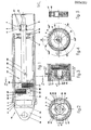
- Figure 1 is a longitudinal cross section of a complete unit
- Figure 2 is a view of a section along the line II - II in Figure 1
- Figure 3 illustrates a portion of the apparatus according to an alternative preferred embodiment
- Figure 4 is a view of a section of an apparatus with three profiled rolling bodies, seen in the direction IV - IV in Figure 3
- Figure 5 illustrates an alternative embodiment of a profiled rolling body.
- the apparatus according to the invention consists of three main parts, an outer cylinder, an inner cylinder and a driving unit.
- the outer cylinder 1 consists of an outer casing or tube 2 with an opening 3 at one end.
- the opening 3, either in an end piece 4 or in the tube itself, is not formed circularly.
- the inner tube 11 is thus taken through the opening 3 linearly but non-rotatably glidably.
- the outer casing 2 has, at its other end portion, a transverse portion 5 with front and back side surfaces 6 and 7 and a cylindrical bearing surface 8.
- the inner cylinder 10 consists of an inner casing or tube 11, the inner surface of which is cylindrical and has helix grooves, preferably with a thread profile, along the major portion of its length.
- the tube 11 slides in and is guided by the opening 3 in the outer casing.
- the inner tube is glidably but unrotatably taken through the opening 3. This can be achieved by the opening being'formed as a polygon, by the outer surface of the inner casing being provided with a long key coacting with a keyway in the end wall piece 4, or in some other known mode.
- the inner tube has a sliding bush 16. Sliding surfaces can alternatively be formed on the inner tube 11 itself.
- Conical disk springs 17, 18 can be mounted on the sliding bush to advantage, as buffers for the end positions of the inner cylinder. At the innermost position, the buffer 18 will come into contact with the transverse portion 5 and at the outmost position the buffer 17 will come into contact with an eccentric plate 25, described in detail below.
- the inner casing has a transverse portion 13 to which are attached two lugs 14 with holes 15.
- the driven member e.g. a lever or arm, can be connected to the hole 15 by means of a pin (not shown).
- the driving means or driving system 20 comprises a shaft 23, rotatably mounted in the transverse portion 5 of the outer casing 2.
- a washer 22 bears against each side surface 6 and 7 of said transverre portion 5, said bearing washers being attached to the shaft 23 and thus prevent the drive shaft 23 from moving axially.
- one end of the drive shaft 23 is formed into a neck 21 for connecting to the rotary power movement.
- the eccentric plate 25 is attached to the other end of the drive shaft 23, and carries a journal 28 disposed eccentrically in relation to the shaft 23.
- the eccentricity between the centre line 24 of the shaft 23 and the centre line of the journal 28 is denoted by e in the Figure.
- a profiled rolling body 33 is mounted on the journal 28, its outer surface having ridges 33 running perpendicular to the journal 28 and being complementary to the helical groove or threads 12 of the inner cylinder 10.
- the diameter of the profiled rolling body 31 is selected such that its ridges 33 engage with the grooves 12 of the inner casing 11.
- a double eccentric plate 26 is attached to the outer end of the journal 28, said plate carrying a second journal 29 diametrically opposite the first journal 28, and at the same distance e from the centre line 24, said journal 29 carrying a second profiled rolling body 32 which is similar to the body 31.
- a stop washer 27 is attached to the outer end of the journal 29, so that the rolling body 32 is axially retained between it and the double eccentric plate 26.
- the profiled roller 32 engages with the helical groove 12 of the inner casing 11 in a position diametrically opposite the engaging position of the roller 31.
- the dimensions of the parts described are selected such that the profiled rollers 31 and 32 engage with a suit:. able .force in the grooves 12 of the inner casipg 11.
- the profiled rollers 31 and 32 will follow or roll in the grooves of the inner casing 11 such that when the shaft 23 has turned one revolution in relation to the casing 11, the rollers have displaced the inner casing a distance corresponding to one pitch of the helical groove 12.
- the inner cylinder 10 and the outer cylinder 1 have also been displaced a pitch axially and linearly in relation to each other but without any mutual turning or rotation.
- the described embodiment allows the selection of a very small pitch for the groove 12, down to one mm or less per revolution, and thus allows a very large gear reduction between the rotary movement and linear movement.
- any play in the translating apparatus can be completely removed and very great positional accuracy obtained, which is necessary, e.g. for positioning movements in -machine' tools.
- Figure 2 is a cross section along the line II-II in Figure 1, illustrating the outer casing 2 and inner casing 11 with its helical groove 12. Also illustrated are the drive shaft 23 with attached eccentric plate 23 and journal 28, as well as the profiled roller 31, rotatably mounted but axially fixed on Journal 28. Finally, the double eccentric plate 26 connecting journals 28 and 29, with the profiled roller 32 on the journal 29 carried by the plate 26 are also illustrated. The eccentricity e between the centre line 24 of the drive shaft and the centre lines of the journals 28 and 29 is given to the left in the Figure.
- the figure also illustrates how engagement between the grooves 12 and the ridges 33 of the profiled rollers 31 and 32 occurs along approximately segment-shaped surfaces, defined by circular lines with radii coires- ponding to the least diameter of the groove 12 and the greatest diameter of the profiled rollers 31 and 32.
- the ridges or threads 33 of the profiled rollers 31 and 32 are perpendicular to the journals 28 and 29, and therefore also perpendicular to the inner cylindrical surface and centre line of the inner casing 11.
- the grooves 12, engaged by the ridges 33 of the rollers 31, 32 form an angle to the centre line of the inner casing 11, this angle depending on the pitch of the helical groove, and there is the same angle between groove 12 and the ridges 33 of the rollers 31, 32.
- the ridges 33 of the profiled rollers 31, 32 must be given a suitable profile, or the journals 28, 29 can be skewed with the pitc angle of the grooves 12 so that the ridges 33 and groove 12 are in the same plane.
- FIG. 3 shows the outmost profiled roller 40 of a driving system 20 with profiled rollers in the form of rolling bearings, the outer ring being formed with ridges in planes parallel to the plane of the rolling bearing.
- the bearing is mounted on an eccentric sleeve 41 on the shaft 23 such that the sleeve is fixed to the shaft and has an eccentricity e" (which is small) between the centre lines of the shaft 23 and the centre line of the journal/eccentric sleeve.
- a small gap 44 thus occurs between the bearing 40 and the groove 12 in the inner sleeve 11.
- Figure 4 is a cross section through an apparatus where there are three . profiled rollers 40,of the embodiment with ball bearings illustrated in Figure 3, evenly distributed round the drive shaft 23.
- the outer casing 2 inner casing 11 with helical grooves or threads 12, the bearing 40 with its centre 42, eccentric sleeve 41, drive shaft 23 with centre 24 and eccentricity e' between centres 24 and 42.
- Lines 45, through both these centres for the three different profiled rollers 40, are evenly distributed at an angle of 120 0 about the shaft 23 " as is apparent from Figure 4.
- Figure 5 finally illustrates an embodiment of a roller in the form of a rolling bearing, where the ridges 33 are formed on a separate ring 47 pressed onto the outer ring of the bearing.
Landscapes
- Engineering & Computer Science (AREA)
- General Engineering & Computer Science (AREA)
- Mechanical Engineering (AREA)
- Chemical & Material Sciences (AREA)
- Combustion & Propulsion (AREA)
- Transportation (AREA)
- Transmission Devices (AREA)
- Retarders (AREA)
Applications Claiming Priority (2)
| Application Number | Priority Date | Filing Date | Title |
|---|---|---|---|
| SE7806574 | 1978-06-05 | ||
| SE7806574A SE411581B (sv) | 1978-06-05 | 1978-06-05 | Anordning for omvandling av roterande rorelse till linjer rorelse |
Publications (3)
| Publication Number | Publication Date |
|---|---|
| EP0006082A2 true EP0006082A2 (fr) | 1979-12-12 |
| EP0006082A3 EP0006082A3 (en) | 1980-01-09 |
| EP0006082B1 EP0006082B1 (fr) | 1986-09-10 |
Family
ID=20335132
Family Applications (2)
| Application Number | Title | Priority Date | Filing Date |
|---|---|---|---|
| EP79850054A Expired EP0006082B1 (fr) | 1978-06-05 | 1979-06-05 | Dispositif pour convertir un mouvement rotatif en un mouvement rectiligne |
| EP79900636A Withdrawn EP0018978A1 (fr) | 1978-06-05 | 1980-01-10 | Appareil de transformation d'un mouvement rotatif en un mouvement lineaire |
Family Applications After (1)
| Application Number | Title | Priority Date | Filing Date |
|---|---|---|---|
| EP79900636A Withdrawn EP0018978A1 (fr) | 1978-06-05 | 1980-01-10 | Appareil de transformation d'un mouvement rotatif en un mouvement lineaire |
Country Status (7)
| Country | Link |
|---|---|
| US (1) | US4337671A (fr) |
| EP (2) | EP0006082B1 (fr) |
| JP (1) | JPS55500470A (fr) |
| DE (1) | DE2967620D1 (fr) |
| DK (1) | DK38280A (fr) |
| SE (1) | SE411581B (fr) |
| WO (1) | WO1980000032A1 (fr) |
Cited By (2)
| Publication number | Priority date | Publication date | Assignee | Title |
|---|---|---|---|---|
| EP0258522A1 (fr) * | 1986-08-28 | 1988-03-09 | Josef Pradler | Unité de transmission linéaire |
| EP0572543A4 (fr) * | 1991-02-25 | 1995-01-18 | Ross Hime Designs Inc | Actuateur miniature lineaire. |
Families Citing this family (10)
| Publication number | Priority date | Publication date | Assignee | Title |
|---|---|---|---|---|
| FR2515859A1 (fr) * | 1981-10-29 | 1983-05-06 | Crouzet Sa | Verin electromagnetique debrayable |
| US4748866A (en) * | 1986-07-03 | 1988-06-07 | Weyer Paul P | Linear helical actuator |
| NL8801948A (nl) * | 1988-08-04 | 1990-03-01 | Haan Mechatronics | Lineaire actuator. |
| US5491372A (en) * | 1991-10-11 | 1996-02-13 | Exlar Corporation | Electric linear actuator with planetary action |
| US5557154A (en) * | 1991-10-11 | 1996-09-17 | Exlar Corporation | Linear actuator with feedback position sensor device |
| DE19600238A1 (de) * | 1996-01-05 | 1997-07-10 | Dewitta Spezialmaschf | Vorrichtung zur Umwandlung einer Dreh- in eine Axialbewegung |
| JP2001208503A (ja) * | 2000-01-25 | 2001-08-03 | Harmonic Drive Syst Ind Co Ltd | リニアアクチュエータの絶対位置検出装置 |
| DE10022115A1 (de) * | 2000-05-06 | 2001-11-08 | Wittenstein Gmbh & Co Kg | Vorrichtung zur Umwandlung einer Dreh-in eine Axialbewegung |
| DE102004054037B3 (de) * | 2004-11-05 | 2006-10-05 | Stabilus Gmbh | Verstellvorrichtung |
| US8065755B2 (en) * | 2009-04-24 | 2011-11-29 | David Chen | Water jet injector for sanitary self-cleaning toilet seat device |
Family Cites Families (14)
| Publication number | Priority date | Publication date | Assignee | Title |
|---|---|---|---|---|
| US2734392A (en) * | 1956-02-14 | Feed screw mechanism- | ||
| FR879530A (fr) * | 1939-03-18 | 1943-02-25 | Barre de commande tubulaire télescopique pour avion | |
| DE855785C (de) * | 1950-06-17 | 1952-11-17 | Herbert Schoen | Elektromechanisches Hubgetriebe |
| US2780740A (en) * | 1955-03-25 | 1957-02-05 | Westinghouse Electric Corp | Linear motion device |
| BE546381A (fr) * | 1955-03-25 | |||
| US3128634A (en) * | 1962-02-21 | 1964-04-14 | Bendix Corp | Screw actuator |
| CH423395A (de) * | 1965-06-16 | 1966-10-31 | Contraves Ag | Schraubgetriebe |
| DE1650834A1 (de) * | 1967-09-14 | 1970-12-03 | Seeliger Dr Ing Kurt | Spindeltrieb |
| DE1927767A1 (de) * | 1969-05-30 | 1970-12-03 | Uhing Joachim Ing | Waelzschrauben-Element |
| DE1949049C3 (de) * | 1969-09-29 | 1980-09-04 | Robert Dr.-Ing. 6308 Butzbach Gaertner | Spindeltrieb |
| US3861226A (en) * | 1972-07-17 | 1975-01-21 | Richard B Stanley | Linear actuator |
| US3965761A (en) * | 1974-03-21 | 1976-06-29 | Stanley Richard B | Linear actuator |
| SE390753B (sv) * | 1975-06-11 | 1977-01-17 | B Nerdin | Anordning for att omvandla en rotationsrorelse till en retlinjig rorelse |
| US4050319A (en) * | 1976-01-16 | 1977-09-27 | Stanley Richard B | Linear actuator |
-
1978
- 1978-06-05 SE SE7806574A patent/SE411581B/sv not_active IP Right Cessation
-
1979
- 1979-06-05 WO PCT/SE1979/000127 patent/WO1980000032A1/fr not_active Ceased
- 1979-06-05 EP EP79850054A patent/EP0006082B1/fr not_active Expired
- 1979-06-05 US US06/190,764 patent/US4337671A/en not_active Expired - Lifetime
- 1979-06-05 JP JP50091279A patent/JPS55500470A/ja active Pending
- 1979-06-05 DE DE7979850054T patent/DE2967620D1/de not_active Expired
-
1980
- 1980-01-10 EP EP79900636A patent/EP0018978A1/fr not_active Withdrawn
- 1980-01-30 DK DK38280A patent/DK38280A/da not_active Application Discontinuation
Cited By (3)
| Publication number | Priority date | Publication date | Assignee | Title |
|---|---|---|---|---|
| EP0258522A1 (fr) * | 1986-08-28 | 1988-03-09 | Josef Pradler | Unité de transmission linéaire |
| EP0572543A4 (fr) * | 1991-02-25 | 1995-01-18 | Ross Hime Designs Inc | Actuateur miniature lineaire. |
| EP0784166A1 (fr) * | 1991-02-25 | 1997-07-16 | Ross-Hime Designs, Incorporated | Actuateur miniature linéaire |
Also Published As
| Publication number | Publication date |
|---|---|
| SE411581B (sv) | 1980-01-14 |
| DK38280A (da) | 1980-01-30 |
| WO1980000032A1 (fr) | 1980-01-10 |
| JPS55500470A (fr) | 1980-07-31 |
| DE2967620D1 (en) | 1986-10-16 |
| US4337671A (en) | 1982-07-06 |
| EP0006082B1 (fr) | 1986-09-10 |
| EP0018978A1 (fr) | 1980-11-26 |
| SE7806574L (fr) | 1979-12-06 |
| EP0006082A3 (en) | 1980-01-09 |
Similar Documents
| Publication | Publication Date | Title |
|---|---|---|
| EP0006082A2 (fr) | Dispositif pour convertir un mouvement rotatif en un mouvement rectiligne | |
| CA1044045A (fr) | Appareil de commande lineaire | |
| US3861221A (en) | Linear actuator | |
| US4487091A (en) | Speed reducer and method for reducing blacklash | |
| US5370012A (en) | Linear actuation roller bearing nut | |
| US5117700A (en) | Miniature linear actuator | |
| US4203328A (en) | Rotary-to-linear-motion converter | |
| US3861226A (en) | Linear actuator | |
| US6516680B1 (en) | Power steering apparatus | |
| US8020463B2 (en) | Rotation/linear motion converting mechanism | |
| GB2091375A (en) | A device for converting rotary motion into linear motion | |
| JPH0338458B2 (fr) | ||
| KR100306650B1 (ko) | 직선구동장치 | |
| US5054393A (en) | Internal worm drive and oscillating roller assembly for use in inking systems for printing presses | |
| US6131479A (en) | Device for converting rotary motion into axial motion | |
| US5154092A (en) | Internal worm drive and oscillating roller assembly for use in inking systems for printing presses | |
| GB2064685A (en) | Friction Gears | |
| US3244021A (en) | Roller bearing nut | |
| JPH08200465A (ja) | 微小送り機構 | |
| GB2211908A (en) | Linear actuator | |
| SU1456657A2 (ru) | Эксцентрична винтова передача | |
| SU1702028A1 (ru) | Фрикционно-винтова передача | |
| JPH07317869A (ja) | 直線駆動装置 | |
| RU2179129C2 (ru) | Рулевой механизм транспортного средства | |
| SU1449721A1 (ru) | Регулируемый подшипник скольжени |
Legal Events
| Date | Code | Title | Description |
|---|---|---|---|
| PUAI | Public reference made under article 153(3) epc to a published international application that has entered the european phase |
Free format text: ORIGINAL CODE: 0009012 |
|
| PUAL | Search report despatched |
Free format text: ORIGINAL CODE: 0009013 |
|
| AK | Designated contracting states |
Designated state(s): BE CH DE FR GB IT LU NL |
|
| AK | Designated contracting states |
Designated state(s): BE CH DE FR GB IT LU NL |
|
| 17P | Request for examination filed | ||
| RAP1 | Party data changed (applicant data changed or rights of an application transferred) |
Owner name: FERNGREN-HANCO AB |
|
| RIN1 | Information on inventor provided before grant (corrected) |
Inventor name: ANDERSSON, PER |
|
| RAP1 | Party data changed (applicant data changed or rights of an application transferred) |
Owner name: STK SVENSKT TILLVAEXTKAPITAL AB |
|
| GRAA | (expected) grant |
Free format text: ORIGINAL CODE: 0009210 |
|
| AK | Designated contracting states |
Kind code of ref document: B1 Designated state(s): BE CH DE FR GB IT LU NL |
|
| PG25 | Lapsed in a contracting state [announced via postgrant information from national office to epo] |
Ref country code: NL Effective date: 19860910 Ref country code: IT Free format text: LAPSE BECAUSE OF FAILURE TO SUBMIT A TRANSLATION OF THE DESCRIPTION OR TO PAY THE FEE WITHIN THE PRESCRIBED TIME-LIMIT;WARNING: LAPSES OF ITALIAN PATENTS WITH EFFECTIVE DATE BEFORE 2007 MAY HAVE OCCURRED AT ANY TIME BEFORE 2007. THE CORRECT EFFECTIVE DATE MAY BE DIFFERENT FROM THE ONE RECORDED. Effective date: 19860910 Ref country code: FR Free format text: THE PATENT HAS BEEN ANNULLED BY A DECISION OF A NATIONAL AUTHORITY Effective date: 19860910 Ref country code: CH Effective date: 19860910 Ref country code: BE Effective date: 19860910 |
|
| REF | Corresponds to: |
Ref document number: 2967620 Country of ref document: DE Date of ref document: 19861016 |
|
| RAP2 | Party data changed (patent owner data changed or rights of a patent transferred) |
Owner name: FERNGREN-HANCO AB |
|
| REG | Reference to a national code |
Ref country code: CH Ref legal event code: PL |
|
| EN | Fr: translation not filed | ||
| NLV1 | Nl: lapsed or annulled due to failure to fulfill the requirements of art. 29p and 29m of the patents act | ||
| PG25 | Lapsed in a contracting state [announced via postgrant information from national office to epo] |
Ref country code: LU Free format text: LAPSE BECAUSE OF NON-PAYMENT OF DUE FEES Effective date: 19870630 |
|
| PLBE | No opposition filed within time limit |
Free format text: ORIGINAL CODE: 0009261 |
|
| STAA | Information on the status of an ep patent application or granted ep patent |
Free format text: STATUS: NO OPPOSITION FILED WITHIN TIME LIMIT |
|
| 26N | No opposition filed | ||
| PGFP | Annual fee paid to national office [announced via postgrant information from national office to epo] |
Ref country code: GB Payment date: 19920529 Year of fee payment: 14 |
|
| PGFP | Annual fee paid to national office [announced via postgrant information from national office to epo] |
Ref country code: DE Payment date: 19920828 Year of fee payment: 14 |
|
| PG25 | Lapsed in a contracting state [announced via postgrant information from national office to epo] |
Ref country code: GB Effective date: 19930605 |
|
| GBPC | Gb: european patent ceased through non-payment of renewal fee |
Effective date: 19930605 |
|
| PG25 | Lapsed in a contracting state [announced via postgrant information from national office to epo] |
Ref country code: DE Effective date: 19940301 |