EP0258533A2 - Dispositif pour insérer un noyau d'enroulement dans une machine de bobinage - Google Patents
Dispositif pour insérer un noyau d'enroulement dans une machine de bobinage Download PDFInfo
- Publication number
- EP0258533A2 EP0258533A2 EP87106746A EP87106746A EP0258533A2 EP 0258533 A2 EP0258533 A2 EP 0258533A2 EP 87106746 A EP87106746 A EP 87106746A EP 87106746 A EP87106746 A EP 87106746A EP 0258533 A2 EP0258533 A2 EP 0258533A2
- Authority
- EP
- European Patent Office
- Prior art keywords
- winding
- sleeve
- winding tube
- slide
- holder
- Prior art date
- Legal status (The legal status is an assumption and is not a legal conclusion. Google has not performed a legal analysis and makes no representation as to the accuracy of the status listed.)
- Granted
Links
- 238000004804 winding Methods 0.000 title claims abstract description 326
- 239000000969 carrier Substances 0.000 claims description 6
- 230000006835 compression Effects 0.000 claims description 4
- 238000007906 compression Methods 0.000 claims description 4
- 125000006850 spacer group Chemical group 0.000 claims description 4
- 238000006073 displacement reaction Methods 0.000 description 4
- 238000000034 method Methods 0.000 description 3
- 239000000853 adhesive Substances 0.000 description 2
- 230000001070 adhesive effect Effects 0.000 description 2
- 238000003780 insertion Methods 0.000 description 2
- 230000037431 insertion Effects 0.000 description 2
- 230000006978 adaptation Effects 0.000 description 1
- 210000000080 chela (arthropods) Anatomy 0.000 description 1
- 238000006243 chemical reaction Methods 0.000 description 1
- 230000002996 emotional effect Effects 0.000 description 1
- 239000000463 material Substances 0.000 description 1
- 230000007704 transition Effects 0.000 description 1
Images
Classifications
-
- B—PERFORMING OPERATIONS; TRANSPORTING
- B65—CONVEYING; PACKING; STORING; HANDLING THIN OR FILAMENTARY MATERIAL
- B65H—HANDLING THIN OR FILAMENTARY MATERIAL, e.g. SHEETS, WEBS, CABLES
- B65H19/00—Changing the web roll
- B65H19/22—Changing the web roll in winding mechanisms or in connection with winding operations
- B65H19/30—Lifting, transporting, or removing the web roll; Inserting core
- B65H19/305—Inserting core
-
- B—PERFORMING OPERATIONS; TRANSPORTING
- B65—CONVEYING; PACKING; STORING; HANDLING THIN OR FILAMENTARY MATERIAL
- B65H—HANDLING THIN OR FILAMENTARY MATERIAL, e.g. SHEETS, WEBS, CABLES
- B65H2301/00—Handling processes for sheets or webs
- B65H2301/40—Type of handling process
- B65H2301/41—Winding, unwinding
- B65H2301/414—Winding
- B65H2301/4148—Winding slitting
- B65H2301/41486—Winding slitting winding on two or more winding shafts simultaneously
- B65H2301/414863—Winding slitting winding on two or more winding shafts simultaneously directly against central support roller
-
- B—PERFORMING OPERATIONS; TRANSPORTING
- B65—CONVEYING; PACKING; STORING; HANDLING THIN OR FILAMENTARY MATERIAL
- B65H—HANDLING THIN OR FILAMENTARY MATERIAL, e.g. SHEETS, WEBS, CABLES
- B65H2301/00—Handling processes for sheets or webs
- B65H2301/40—Type of handling process
- B65H2301/41—Winding, unwinding
- B65H2301/417—Handling or changing web rolls
- B65H2301/418—Changing web roll
- B65H2301/4182—Core or mandrel insertion, e.g. means for loading core or mandrel in winding position
- B65H2301/41826—Core or mandrel insertion, e.g. means for loading core or mandrel in winding position by gripping or pushing means, mechanical or suction gripper
-
- B—PERFORMING OPERATIONS; TRANSPORTING
- B65—CONVEYING; PACKING; STORING; HANDLING THIN OR FILAMENTARY MATERIAL
- B65H—HANDLING THIN OR FILAMENTARY MATERIAL, e.g. SHEETS, WEBS, CABLES
- B65H2301/00—Handling processes for sheets or webs
- B65H2301/40—Type of handling process
- B65H2301/41—Winding, unwinding
- B65H2301/417—Handling or changing web rolls
- B65H2301/418—Changing web roll
- B65H2301/41829—Changing web roll positioning the core, e.g. in axial direction
Definitions
- the invention relates to a device for introducing a winding tube into a winding machine with at least one support roller and at least two winding frames with opposing thorns receiving the winding tube.
- the web extending across the width of the support roller is severed after the winding rollers have reached the intended diameter and have ejected the finished winding roller.
- empty winding tubes are placed by hand between the mandrels of the winding frames and then into their winding position on the support roller. In order to attach the start of the web to the empty winding tubes, they are provided with an adhesive.
- the invention has for its object the insertion of to simplify and accelerate empty winding tubes in a winding machine and to let them run largely automatically.
- At least one winding sleeve gripper which can be moved between a winding tube receiving position and a winding tube dispensing position which is essentially axially aligned with the mandrels.
- the winding tube receiving position lies outside the support roller, so that the winding tubes can either be inserted into the winding tube gripper safely by hand or can be automatically picked up by the winding tube gripper.
- the winding tube gripper is pivotally mounted above the support roller between the winding tube receiving position and the winding tube dispensing position transversely to the support roller axis.
- the winding tube receptacle position is located above the support roller, for example in its longitudinal center plane in a free space which is also accessible when the winding rollers have reached their full diameter.
- a guide cross member arranged above the support roller, which serves as a carrier and guide for the winding blocks.
- a sleeve pliers can be arranged below this pivot axis in the vicinity of the support roller, so that the winding tube holder is located position above the support roller approximately in the longitudinal center plane and the winding tube delivery position laterally pivoted out of the longitudinal center plane.
- the winding core gripper In order to be able to bring the winding core gripper into the winding core receiving position above the support roller and into the winding core dispensing position to the side of the central longitudinal plane of the support roller in the area of the mandrels on the winding blocks, the winding core gripper should also be designed to be telescopic.
- the winding tube gripper can be mounted on a slide which is displaceable in guides on the guide crossmember, so that an adaptation to different web formats and additionally moving out of the winding tube gripper in the direction of the axis of the support roller is possible.
- the slide can then be fixed in place by means of a locking device which acts between the slide and the guide crossmember.
- winding rollers are arranged on a gap on both sides of the central longitudinal plane of the support roller, with end faces aligned in pairs in each case, two winding tube grippers which can be pivoted in opposite directions can be arranged on each slide.
- the guides for the slides are extended beyond the length of the support roller.
- the slides with the winding tube grippers can thus be pulled out of the winding machine, equipped with winding tubes and pushed back into the winding machine.
- the winding sleeves collide with their end faces the and the first winding tube pushed into the winding machine abuts against a stop, as a result of which the position of all the winding tubes with respect to the winding stations is determined.
- the slides can be coupled to one another by means of a spacer corresponding to the length of the winding cores to be inserted, so that the carriages with the winding core grippers as a whole Let it slide out of the winding machine in the axial direction.
- the prerequisite is that the guides for the slides are extended over the length of the back-up roller approximately in accordance with the total length of the winding tubes to be inserted.
- At least one winding tube holder can also be mounted on a winding frame. In this case it is necessary to pick up the winding tubes in the area of the winding stations by means of the winding tube grippers.
- the winding tube gripper in its simplest form consists of a carrier, a slide that is mounted on the carrier and a sleeve pin holder that is pivotably mounted on the slide.
- the sliding of the slide relative to the carrier and the pivoting of the sleeve clamp holder relative to the slide are preferably carried out with the help of a hydraulic or pneumatic piston-cylinder unit or by an electric motor drive.
- a hydraulic or pneumatic piston-cylinder unit or by an electric motor drive.
- the winding tube gripper can also consist of a carrier, a slide guide pivotally mounted on the carrier and a sleeve pliers holder designed as a slide.
- the swivel axis is located near the attachment to the guide crossmember.
- the slide can be moved and the winding sleeve gripper swiveled by a hydraulic or pneumatic piston-cylinder unit or by an electric motor drive.
- the telescoping and pivoting of the winding tube gripper can be carried out by means of a single actuation device if the slide guide for the sleeve-pincer holder designed as a slide is part of another slide which is guided in the pivotably mounted slide guide and is coupled to the carrier via a link. In this case, however, it is necessary to control the swiveling out and the telescoping in such a way that no incorrect movements occur.
- the slide is formed in two parts and an upper slide part is coupled to a handlebar, while a lower slide part carries the slide guide for the sleeve tongs holder.
- a hydraulic or pneumatic piston-cylinder unit between the pivotable slide guide and the lower slide part and a further hydraulic or pneumatic piston-cylinder unit between the lower slide part and the sleeves pliers holder arranged.
- the path of the upper slide part is limited by two stops arranged on the pivotable slide guide, the path of the lower slide part by a stop arranged on the upper slide part and a stop arranged on the slide guide, and the path of the sleeve pliers holder by a stop which interacts with the lower slide part.
- Springs arranged between the two slide parts and between the lower slide part and the sleeve tongs holder one of which is designed as a tension spring and one as a compression spring, ensure that the winding tube gripper is pivoted out before telescoping and the tube tongs are closed before the tube tongs holder is retracted.
- the piston-cylinder unit coupled to the lower slide part and the sleeve tong holder does not act directly on the sleeve tong holder, but indirectly via a locking lever connected to the sleeve tong.
- these can be coupled to one another via a toothing.
- Another means of controlling the winding tube receptacle and the winding tube output in accordance with the position of the winding tube gripper consists of a bolt which interacts with the tube tongs holder and the carrier and is movably mounted on the pivotable slide guide against spring force. In the swiveled-in position of the winding tube gripper, this bolt is unlocked, while in the swiveled-out position, the tube pliers holder holds in the retracted position so that an opening of the sleeve pliers in the winding tube delivery position is possible without moving the sleeve pliers holder.
- a further possibility of bringing the winding tube gripper from the winding tube receiving position into the winding tube dispensing position consists in slidably mounting the carrier of the winding tube gripper on the slide transversely to the support roller axis.
- the winding tubes can be pushed onto this tube trough from one end of the support roller, with their end faces abutting, until there is a winding tube in the area of each winding station.
- the tube trough can also be slidably supported by means of guide rails on supports arranged on the winding brackets, so that it can be pulled out of the winding machine in the axial direction of the support roller and can be covered with winding tubes.
- the carriers are preferably provided with rollers.
- the sleeve channel can also be designed to be height-adjustable.
- the winding tube gripper can also be designed as a simple pivot lever; then its pivot axis is above the support roller, and the sleeve pliers are directed upwards towards the guide crossmember in the winding tube receiving position.
- the winding sleeve grippers designed as swivel levers are preferably arranged on the winding frames. Depending on the position of the swivel axis and the distance of the mandrels on the winding brackets, it is sufficient to make the swivel levers inextensible or telescopic.
- At least one core carrier is preferably mounted above the core tongs in the region of the winding core receiving position for each core on a guide cross-member running above the support roller.
- This core carrier transfers the winding tubes to the winding tube grippers, and these swing out in order to transfer the winding tubes to the mandrels of the winding blocks.
- Each sleeve carrier preferably consists of sleeve tongs which open to the winding sleeve gripper and are mounted on slides which can be displaced in guides on the guide crossmember. If these guides are extended beyond the length of the back-up roll, as in the other versions, the winding tubes can be inserted into the tube carriers outside the winding machine.
- the winding sleeves inserted into the sleeve supports can be pushed axially through the sleeve tongs on the swivel levers; they are detected when the sleeve pliers are closed and moved out of the sleeve carriers when the pivoting lever is pivoted, provided that these sleeve carriers can be pivoted and opened, for example, against spring force.
- the winding tube gripper can be arranged on the pressure roller crossmember.
- the pressure roller rocker itself can be designed as a winding sleeve gripper if at least one sleeve pliers is arranged on the pressure roller rocker which holds the empty winding sleeve in contact with the pressure rollers on the pressure roller rocker.
- the winding sleeves can be inserted by hand into the sleeve pliers arranged on the pressure roller arms. If the pressure roller rockers do not swivel back far enough for structural reasons, an additional swivel joint can be attached to the pressure roller rockers.
- This design has the advantage that the winding tubes are always brought exactly into the area of the mandrels on the winding frames, regardless of their diameter, without a complex mechanism for positioning the winding tubes being required.
- This pivoting lever can, similarly to the aforementioned pressure roller rocker, be pivoted out of its winding tube receiving position, in which the winding tube is placed in the winding tube gripper, into its winding tube delivery position, in which the winding tube is delivered to the mandrels on the winding jacks.
- the swivel lever is preferably mounted in a swivel bearing of a slide which can be displaced on the pressure roll crossmember.
- the winding tube gripper In view of the fact that the swivel levers have to swivel under the pressure roller traverse in order to get from the winding tube receiving position into the winding tube dispensing position, the winding tube gripper must be adjustable in height.
- the pressure roller traverse can be designed such that it can be raised and lowered, or the winding tube gripper can be arranged on the pressure roller traverse so that it can be raised and lowered.
- the winding sleeve grippers need not be designed as swivel levers, but it is sufficient to arrange telescopic winding sleeve grippers provided with sleeve pliers on a slide that can be displaced on the pressure roller crossbar.
- the tube tongs remove the winding tubes from a tube channel arranged above the support roller. Since the winding tube delivery position is then lower than the winding tube receiving position, it is also necessary to lift and either the pressure roller traverse or the winding tube gripper on the pressure roller traverse trained to be lowerable.
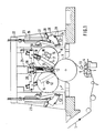
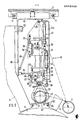
- a material web 1 for example a paper web
- a guide roller 2 and a deflection roller 3 to several longitudinal cutters, each consisting of an upper knife 4 and a lower knife 5, and divided into a number of narrower paper webs which are wound into rolls in the winding machine.
- the paper webs arrive at a support roller 6 which is designed as a suction roller and which supports the winding rollers and sets them in rotation when they are rolled up.
- winding stations 7 to 11 are arranged above the support roller 6, but laterally from the vertical longitudinal center plane of the support roller 6.
- the winding core of the rolls consists of winding sleeves 12.
- the winding sleeves 12 are guided by means of mandrels 17 in pairs alternately on one and on the other side of the longitudinal center plane of the support roller 6 arranged winding stands 14.
- winding carriages 15 are arranged on the winding brackets 14, which can be moved along a guide on the winding brackets 14 by means of hydraulic or pneumatic piston-cylinder units 18.
- the mandrels 17 can be axially displaced by means of a traversing motor 16 arranged on each roll-up carriage 15 in order to Release or take up winding sleeves 12.
- the winding brackets 14 are slidably mounted in guides 19 on a guide cross-piece 21 running in the axial direction of the support roller 6 and can be adjusted to the required winding width by means of a traversing motor 20.
- the guide cross member 21 is fastened to cross members 22 carried by stands 23.
- an additional pressure is exerted on the initially flexible winding sleeve during the first windings at the start of winding.
- This is achieved by pressure roller rockers 27 with pressure rollers 30 arranged on a vertically movable pressure roller crossbeam 24.
- the pressure roller rockers 27 are pivoted by means of a piston-cylinder unit 28 and are mounted on a slide 26 which can be moved in guides 29 on the pressure roller crossbar 24.
- a winding tube gripper 33 is arranged above the support roller 6 in the free space between the winding rollers 7 to 11.
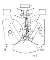
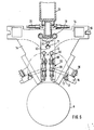
- a guide carrier 32 (FIG. 2) runs below the guide cross member 21, which extends over the length of the support roller 6 and beyond by such a part that the winding tubes 12 can be inserted into the winding tube gripper 33 outside the winding machine.
- the winding tube gripper 33 therefore consists of a carrier 31 which can be moved on the guide carrier 32, on which a carriage 34 which can be displaced in the vertical direction is guided.
- a sleeve clamp holder 35 is articulated on the slide 34 in a pivot axis 36.
- the carriage 34 is moved by means of a piston-cylinder unit 37, while the sleeve tongs holder 35 by means of a piston-Zy linder unit 38 is pivoted.
- a sleeve pliers 39 consisting of two jaws is arranged.
- the winding tube 12 is held in the tube pliers 39 by means of pincer rollers 40.
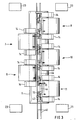
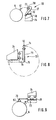
- the winding tube grippers 33 are shifted on the guide carrier 32 until they lie outside the region of the support roller 6. Then a winding tube 12 is inserted by hand into two adjacent winding tube grippers 33 and pushed along the guide carrier 32 over the support roller 6. Although the winding rolls lie on a gap, but with the end faces aligned in pairs, the winding sleeves 12 with the abutting end faces can be pushed into the winding machine until the first winding sleeve 12 abuts a stop on the last winding bracket 14 corresponding to the winding station 8 (FIG. 3). With sufficient length accuracy, the other winding tubes 12 lie exactly in the area of the winding stations 7, 9, 10, 11.
- the piston-cylinder units 38 are first actuated to pivot the sleeve tong holder 35, and then the slide 34 is lowered using the piston-cylinder unit 37.
- the winding tubes 12 reach into the region of the mandrels 17 on the roll-up carriage 15.
- the mandrels 17 are moved into the winding tubes 12 with the aid of the displacement motors 16, and the winding tube grippers 33 are returned to their original position, the winding tubes 12 being moved from the Sleeve pliers 39 are released.
- the sleeves 12 held by the mandrels 17 on the roll-up carriage 15 are moved against the support roller 6, the pressure roller rockers 27 with the rollers 30 are lowered onto the winding sleeves 12, and the winding can begin.
- guide carrier 32 is designed as a T-carrier in FIG. 2, parallel guide rods 41 are shown in FIGS. 3, 4 and 5, on which carriages 42 are arranged displaceably. These carriages 42 can each be locked on the guide cross member 21 when they have assumed the correct position in relation to the winding stations 7 to 11.
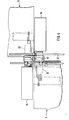
- Axial displacement of the winding tube gripper 33 is not necessary if, as shown in FIG. 5, a tube trough 62 is arranged in the longitudinal median plane above the support roller 6.
- This sleeve channel 62 can rest with guide rails 63 stationary on rollers 64 of the winding blocks 14, so that the winding blocks 14 remain movable for changing the format without the sleeve channel 62 emotional.
- the winding sleeves 12 are pushed into the winding machine on the sleeve groove 62 and, after the foremost one has hit a stop, are in the winding sleeve receiving position in the region of the individual winding stations 7 to 11.
- the sleeve channel 62 on the rollers 64 so that they can move out of the area above the support roller 6 and can be provided with winding tubes 12 outside the support roller 6. Then the sleeve trough 62 is pushed back into the winding machine until the winding sleeves 12 have reached their receiving positions.
- a pivot holder 145 is arranged with a carriage guide 45, on which a two-part carriage consisting of an upper carriage part 50 and a lower carriage part 51 is guided is.
- a link 49 is arranged between the upper slide part 50 and a lateral extension 85 of the slide 42, while a further slide guide 52 for a sleeve pliers holder 46 designed as a slide is arranged on an extension 86 on the lower slide part 51.
- a piston-cylinder unit 47 is articulated on the swivel holder 145 and on the lower slide part 51 and a further piston-cylinder unit 48 on the lower slide part 51 and a locking lever 80 for the sleeve pliers 39.
- a tension spring 58 is arranged between the upper slide part 50 and the lower slide part 51 and a compression spring 59 is arranged between the extension 86 on the lower slide part 51 and the sleeve clamp holder 46.
- the free path of the upper slide part 50 is limited by adjustable stops 53, 54 fastened to the swivel holder 145, the free path of the second slide part 51 by an adjustable stop 55 arranged on the upper slide part 50 and an adjustable further stop 56 arranged on the slide guide 45.
- the path of the sleeve pliers holder 46 is determined by an adjustable stop 57 which interacts with the slide guide 52.
- a bolt 61 is articulated on the slide guide 52 and has at its one free end a locking lug 66 which interacts with a projection 67 on the sleeve pliers holder 46.
- the other free end of the bolt 61 interacts with a plunger 84 arranged on the extension of the slide 42 in such a way that unlocking takes place in the illustrated vertical, right position of the swivel holder 145.
- the winding tube gripper 33 is in the winding tube receiving position.
- the piston-cylinder unit 47 is fully retracted so that the upper slide part 50 bears against the stop 53 and the lower slide part 51 bears against the stop 55.
- the handlebar 49 thereby holds the slide guide 45 in the vertical position shown.
- the piston-cylinder unit 48 has already moved back a certain distance from its fully extended position, so that the sleeve pliers 39 are closed over the winding sleeve 12.
- the piston-cylinder unit 48 is extended again. Since the latch 61 with its locking lug 66 is now behind the projection 67, the sleeve pliers holder 46 does not move, but the sleeve pliers 39 open immediately. After the winding tube 12 has been taken over by the mandrels 17 on two adjacent winding frames 14, the piston-cylinder units 47, 48 are actuated again in such a way that the winding tube gripper 33 returns to the winding tube receiving position.
- the winding tube grippers 33 are mounted on the winding frames 14, and each consist of a simple pivot lever 68 which is mounted on the winding frames 14 in a pivot axis 69.
- sleeve pliers 39 are arranged at the upward free end of the pivot lever 68.
- the pivot axis 69 is arranged on the respective winding bracket 14, and the length of the pivot lever 68 is dimensioned such that the sleeve pliers 39 when pivoting the pivot lever 68 by means of a pivot drive, for example an electric drive, reach the mandrels 17 on the winding blocks 14 and the Winding sleeves 12 can be adopted.
- a pivot drive for example an electric drive
- a sleeve carrier 70 which is provided with sleeve pliers 71, is arranged on the guide cross member 21 above the pivoting lever 68.
- the winding sleeves 12 are inserted into these sleeve tongs 71, which are then taken over by the sleeve tongs 39 on pivoting levers 68.
- This sleeve carrier 70 can be slidably arranged on the guide cross members 21, so that the winding sleeves 12 except half of the winding machine in the sleeve pliers 71.
- the winding tubes 12 in the sleeve tongs 71 can be pushed into the machine at the level of the sleeve tongs 39 and taken over by the sleeve tongs 39 on the pivot levers 68.
- the sleeve tongs 71 must be movable so that they release the winding tubes 12 when the pivoting levers 68 pivot from the winding tube receiving position into the winding tube dispensing position. This is possible with a resilient mounting of the sleeve pliers 71.
- the pressure roller rockers 27 form the winding sleeve grippers 33.
- a sleeve pliers 72 is arranged on the pressure roller rockers 27 in the region of the pressure rollers 30, into which a winding tube 12 can be inserted.
- the winding tube 12 then lies on the pressure rollers 30 and is positioned with the aid of these pressure rollers 30 with respect to the mandrels 17 in the winding frames 14. Since the pressure roller rockers 27 are pivoted back during winding, it is easily possible to insert the winding tubes 12 into the sleeve tongs 72 on the pressure roller blades 27 during this time.
- pressure roller rockers 27 are not far for structural reasons. can swivel back enough, it is possible to provide an additional joint in the pressure roller rockers 27 in order to be able to pivot the pressure rollers 30 back into an almost horizontal position. In this case, a lock in the stretched state of the pressure roller rocker 27 is required to the neces to be able to reach pressure against the 'winding tubes 12 at the beginning of the winding process.
- FIG. 8 A further possibility of arranging a winding tube gripper 33 on the pressure roller crossbars 24 is shown in FIG. 8.
- a carriage 76 is slidably mounted on the pressure roller crossbeam 24.
- a telescopic swivel lever 73 is articulated, which carries at its free end a sleeve tongs 74 for receiving a winding tube 12.
- the sleeve pliers 74 are located in an area of the winding machine that is easily accessible for inserting a winding sleeve 12. This is the winding tube receiving position.
- the transition into the winding tube dispensing position takes place by pivoting through approximately 270 ° around the pivot bearing 75 under the pressure roller cross member 24. Then the telescopic pivot lever 73 is extended until the sleeve pliers 74 reach the area of the mandrels 17 on the winding frames 14. In order to be able to set the correct height of the sleeve pliers 74 with respect to the mandrels 17, either the pressure roller crossbeam 24 can be adjusted in height by means of a lifting drive 25 (FIG. 1), or the slide 76 is arranged on the pressure roller crossbeam 24 such that it can be moved in height .
- the winding tube gripper 33 can be designed as a piston-cylinder unit which is arranged displaceably below the pressure roller crossbeam 24.
- the pressure roller crossbeam 24 is raised by means of the lifting drive 25 so that the end of the piston-cylinder unit 78 is attached arranged sleeve pliers 79 'can remove a winding tube 12 on the tube trough 62.
- All embodiments of the winding tube gripper according to the invention have in common that they can be combined with a conventional winding machine without difficulty, without the need for expensive conversion work.
- the device according to the invention can thus also be retrofitted into existing winding machines; it considerably simplifies and speeds up the operation of these winding machines.
Landscapes
- Replacement Of Web Rolls (AREA)
- Storage Of Web-Like Or Filamentary Materials (AREA)
- Manufacture Of Motors, Generators (AREA)
- Preparation Of Compounds By Using Micro-Organisms (AREA)
- Pharmaceuticals Containing Other Organic And Inorganic Compounds (AREA)
- Saccharide Compounds (AREA)
Priority Applications (1)
| Application Number | Priority Date | Filing Date | Title |
|---|---|---|---|
| AT87106746T ATE74872T1 (de) | 1986-08-27 | 1987-05-08 | Vorrichtung zum einbringen einer wickelhuelse in eine wickelmaschine. |
Applications Claiming Priority (2)
| Application Number | Priority Date | Filing Date | Title |
|---|---|---|---|
| DE3629024A DE3629024C3 (de) | 1986-08-27 | 1986-08-27 | Vorrichtung zum Einbringen einer Wickelhülse in eine Wickelmaschine |
| DE3629024 | 1986-08-27 |
Publications (3)
| Publication Number | Publication Date |
|---|---|
| EP0258533A2 true EP0258533A2 (fr) | 1988-03-09 |
| EP0258533A3 EP0258533A3 (en) | 1989-11-15 |
| EP0258533B1 EP0258533B1 (fr) | 1992-04-15 |
Family
ID=6308230
Family Applications (1)
| Application Number | Title | Priority Date | Filing Date |
|---|---|---|---|
| EP87106746A Expired - Lifetime EP0258533B1 (fr) | 1986-08-27 | 1987-05-08 | Dispositif pour insérer un noyau d'enroulement dans une machine de bobinage |
Country Status (8)
| Country | Link |
|---|---|
| US (2) | US4909454A (fr) |
| EP (1) | EP0258533B1 (fr) |
| JP (1) | JP2809629B2 (fr) |
| AT (1) | ATE74872T1 (fr) |
| CA (1) | CA1297663C (fr) |
| DE (2) | DE3629024C3 (fr) |
| ES (1) | ES2031084T3 (fr) |
| FI (1) | FI86530C (fr) |
Cited By (5)
| Publication number | Priority date | Publication date | Assignee | Title |
|---|---|---|---|---|
| WO1997047547A1 (fr) * | 1996-06-13 | 1997-12-18 | Beloit Technologies, Inc. | Dispositif d'insertion de noyau d'une bobineuse |
| EP0921084A1 (fr) * | 1997-12-05 | 1999-06-09 | Voith Sulzer Papiertechnik Patent GmbH | Dispositif de bobinage pour une bobineuse-refendeuse |
| EP2436630A3 (fr) * | 2010-09-30 | 2012-05-23 | Voith Patent GmbH | Dispositif d'introduction de noyaux distancés les uns des autres dans un dispositif d'enroulement |
| AT511483A5 (de) * | 2008-09-22 | 2012-12-15 | Metso Paper Inc | Wickelvorrichtung für eine faserbahn und verfahren zum wickeln von rollen von teilbahnen in der wickelvorrichtung |
| EP2669223A1 (fr) | 2012-05-29 | 2013-12-04 | Metso Paper Inc. | Procédé et dispositif pour l'enroulement de bandes de fibres, notamment de bandes partielles de papier et de carton, notamment de bandes partielles de papier et de carton |
Families Citing this family (22)
| Publication number | Priority date | Publication date | Assignee | Title |
|---|---|---|---|---|
| DE3737503A1 (de) * | 1987-11-05 | 1989-05-24 | Beloit Corp | Rollenschneidemaschine |
| DE3832601C1 (en) * | 1988-09-26 | 1989-12-07 | J.M. Voith Gmbh, 7920 Heidenheim, De | Winding machine for web-like material, especially paper |
| JPH0733195B2 (ja) * | 1988-12-29 | 1995-04-12 | 石川島播磨重工業株式会社 | 巻取装置 |
| DE4219485A1 (de) * | 1992-01-24 | 1993-12-16 | Jagenberg Ag | Wickelmaschine zum Aufwickeln einer Papier- oder Kartonbahn |
| FI932674A7 (fi) * | 1992-06-13 | 1993-12-14 | Jagenberg Ag | Rullmaskin foer rullning av en pappers- eller kartongbana |
| GB2274835B (en) * | 1993-02-05 | 1996-12-18 | Fuji Iron Works | Automatic slitter rewinder machine |
| IT1274404B (it) * | 1994-04-29 | 1997-07-17 | Fmc Corp Societa Del Delaware | Trasduttore di forza ad uscita digitale per apparecchio per il bilanciamento delle ruote |
| FI100467B (fi) * | 1994-05-26 | 1997-12-15 | Valmet Corp | Menetelmä ja laite rainan rullauksessa |
| KR100357938B1 (ko) * | 1995-01-12 | 2003-03-26 | 니시무라세이사쿠쇼코우.,엘티디. | 웹 권취장치 |
| DE19508207C2 (de) * | 1995-03-08 | 1998-05-14 | Kampf Gmbh & Co Maschf | Rollenschneid- und Wickelmaschine |
| DE29513526U1 (de) * | 1995-08-23 | 1997-01-09 | Beloit Technologies, Inc., Wilmington, Del. | Vorrichtung zum automatischen Hülsenzuführen in Rollenschneidemaschinen des Stützwalzentyps |
| DE19729530C2 (de) * | 1997-07-10 | 1999-05-20 | Voith Sulzer Finishing Gmbh | Rollenschneider |
| DE19858516C2 (de) * | 1998-12-18 | 2002-02-07 | Voith Paper Patent Gmbh | Rollenwickelvorrichtung |
| US8042761B2 (en) * | 2002-02-28 | 2011-10-25 | Kimberly-Clark Worldwide, Inc. | Center/surface rewinder and winder |
| US7909282B2 (en) * | 2002-02-28 | 2011-03-22 | Kimberly-Clark Worldwide, Inc. | Center/surface rewinder and winder |
| US8757533B2 (en) * | 2002-02-28 | 2014-06-24 | Kimberly-Clark Worldwide, Inc. | Center/surface rewinder and winder |
| US8535780B2 (en) * | 2009-10-06 | 2013-09-17 | Kimberly-Clark Worldwide, Inc. | Coreless tissue rolls and method of making the same |
| US8364290B2 (en) | 2010-03-30 | 2013-01-29 | Kimberly-Clark Worldwide, Inc. | Asynchronous control of machine motion |
| EP2669224B1 (fr) | 2012-05-29 | 2019-05-22 | Valmet Technologies, Inc. | Procédé et dispositif dans un enrouleur de bandes, en particulier l'alimentation des nouveaux noyaux à un enrouleur. |
| US9352921B2 (en) | 2014-03-26 | 2016-05-31 | Kimberly-Clark Worldwide, Inc. | Method and apparatus for applying adhesive to a moving web being wound into a roll |
| CN114901576B (zh) * | 2020-01-13 | 2025-11-28 | 施洛伊尼格股份公司 | 导线进料装置 |
| JP7800506B2 (ja) * | 2023-06-07 | 2026-01-16 | 株式会社村田製作所 | 巻芯保持装置および無人搬送車 |
Family Cites Families (10)
| Publication number | Priority date | Publication date | Assignee | Title |
|---|---|---|---|---|
| FR1407836A (fr) * | 1964-06-26 | 1965-08-06 | Fmc Corp | Appareil à manipuler des tubes et des broches pour machine à enrouler des matières en bande |
| GB1432378A (en) * | 1972-10-21 | 1976-04-14 | Wyeth John & Brother Ltd | Fused carbocyclic ring derivatives of pyridine |
| GB1444917A (en) * | 1972-11-03 | 1976-08-04 | Loewy Robertson Eng Co Ltd | Spool transfer apparatus |
| DE2948877C2 (de) * | 1979-12-05 | 1982-02-18 | Jagenberg-Werke AG, 4000 Düsseldorf | Doppeltragwalzen-Wickelmaschine |
| DE3102894C2 (de) * | 1981-01-29 | 1983-01-20 | Jagenberg-Werke AG, 4000 Düsseldorf | Vorrichtung zum getrennten Aufwickeln längsgeteilter Bahnen |
| US4422588A (en) * | 1981-09-28 | 1983-12-27 | The Black Clawson Company | Slitter-rewinder system |
| DE3243994C2 (de) * | 1982-11-27 | 1986-07-10 | J.M. Voith Gmbh, 7920 Heidenheim | Wickelmaschine zum Aufwickeln einer längsgeteilten Bahn |
| DE3308271A1 (de) * | 1983-03-09 | 1984-09-20 | Jagenberg AG, 4000 Düsseldorf | Vorrichtung zum aufwickeln laengsgeteilter bahnen und verfahren beim wickelrollen/huelsenwechsel |
| US4697755A (en) * | 1984-08-27 | 1987-10-06 | Hiroshi Kataoka | Rewinder with slitter |
| DE3540490C1 (de) * | 1985-11-15 | 1987-03-12 | Voith Gmbh J M | Wickelmaschine zum Aufwickeln einer laengsgeteilten Bahn |
-
1986
- 1986-08-27 DE DE3629024A patent/DE3629024C3/de not_active Expired - Fee Related
- 1986-08-27 DE DE3645209A patent/DE3645209C2/de not_active Expired - Lifetime
-
1987
- 1987-05-08 AT AT87106746T patent/ATE74872T1/de not_active IP Right Cessation
- 1987-05-08 ES ES198787106746T patent/ES2031084T3/es not_active Expired - Lifetime
- 1987-05-08 EP EP87106746A patent/EP0258533B1/fr not_active Expired - Lifetime
- 1987-08-25 JP JP62209429A patent/JP2809629B2/ja not_active Expired - Fee Related
- 1987-08-26 FI FI873709A patent/FI86530C/fi not_active IP Right Cessation
- 1987-08-26 US US07/089,891 patent/US4909454A/en not_active Expired - Lifetime
- 1987-08-26 CA CA000545402A patent/CA1297663C/fr not_active Expired - Fee Related
-
1989
- 1989-11-06 US US07/433,022 patent/US5000395A/en not_active Expired - Lifetime
Cited By (8)
| Publication number | Priority date | Publication date | Assignee | Title |
|---|---|---|---|---|
| WO1997047547A1 (fr) * | 1996-06-13 | 1997-12-18 | Beloit Technologies, Inc. | Dispositif d'insertion de noyau d'une bobineuse |
| US6155515A (en) * | 1996-06-13 | 2000-12-05 | Doerfel; G. Walter | Core-insertion device for a winding machine |
| EP0921084A1 (fr) * | 1997-12-05 | 1999-06-09 | Voith Sulzer Papiertechnik Patent GmbH | Dispositif de bobinage pour une bobineuse-refendeuse |
| US6089495A (en) * | 1997-12-05 | 2000-07-18 | Voith Sulzer Papiertechnik Patent Gmbh | Winding device and method for a reel cutter |
| AT511483A5 (de) * | 2008-09-22 | 2012-12-15 | Metso Paper Inc | Wickelvorrichtung für eine faserbahn und verfahren zum wickeln von rollen von teilbahnen in der wickelvorrichtung |
| AT511483B1 (de) * | 2008-09-22 | 2013-02-15 | Metso Paper Inc | Wickelvorrichtung für eine faserbahn und verfahren zum wickeln von rollen von teilbahnen in der wickelvorrichtung |
| EP2436630A3 (fr) * | 2010-09-30 | 2012-05-23 | Voith Patent GmbH | Dispositif d'introduction de noyaux distancés les uns des autres dans un dispositif d'enroulement |
| EP2669223A1 (fr) | 2012-05-29 | 2013-12-04 | Metso Paper Inc. | Procédé et dispositif pour l'enroulement de bandes de fibres, notamment de bandes partielles de papier et de carton, notamment de bandes partielles de papier et de carton |
Also Published As
| Publication number | Publication date |
|---|---|
| DE3645209C2 (de) | 1995-11-02 |
| FI86530C (fi) | 1992-09-10 |
| FI873709A0 (fi) | 1987-08-26 |
| US5000395A (en) | 1991-03-19 |
| JP2809629B2 (ja) | 1998-10-15 |
| JPS6360853A (ja) | 1988-03-16 |
| EP0258533A3 (en) | 1989-11-15 |
| FI873709A7 (fi) | 1988-02-28 |
| DE3629024C3 (de) | 1994-09-01 |
| EP0258533B1 (fr) | 1992-04-15 |
| DE3629024C2 (fr) | 1994-09-01 |
| ES2031084T3 (es) | 1992-12-01 |
| CA1297663C (fr) | 1992-03-24 |
| DE3629024A1 (de) | 1988-03-10 |
| FI86530B (fi) | 1992-05-29 |
| ATE74872T1 (de) | 1992-05-15 |
| US4909454A (en) | 1990-03-20 |
Similar Documents
| Publication | Publication Date | Title |
|---|---|---|
| EP0258533B1 (fr) | Dispositif pour insérer un noyau d'enroulement dans une machine de bobinage | |
| DE2918687C2 (fr) | ||
| DE2918725C2 (fr) | ||
| EP1100643B1 (fr) | Procede et dispositif pour separer transversalement des rubans ou des toles dans la ligne de laminage ou de transport | |
| DE3645252C2 (de) | Vorrichtung zum Wickeln von mehreren durch Längsschneiden einer breiten Materialbahn gebildeten schmalen Materialbahnen zu Vorratsrollen | |
| WO1992021599A1 (fr) | Procede et dispositif d'empilement | |
| DE3939596A1 (de) | Vorrichtung zum schneiden von gestapeltem, blattfoermigem gut | |
| EP1705142B1 (fr) | Dispositif d'enroulement pour un materiau en bande ou en ruban alimenté de façon continue | |
| DE4013066C2 (de) | Spulenwechselvorrichtung | |
| DE3822572C2 (fr) | ||
| DE3345665C2 (de) | Vorrichtung zum Halten der Walzstange und zum Führen des Walzgutes | |
| DE4304469A1 (de) | Wickelvorrichtung mit Rollenwechseleinrichtung für aufzuwickelndes bandförmiges Wickelgut | |
| DE4441142C2 (de) | Zweirichtungsschwenkrahmen einer Papierrollenwechseleinrichtung | |
| DE3715475C2 (fr) | ||
| EP0406581B1 (fr) | Dispositif pour couper une bande sur un rouleau d'inversement | |
| DE19612729C2 (de) | Vorrichtung zur Aufnahme oder Übernahme von Wickelkernen | |
| DE3537727A1 (de) | Spulenwechselverfahren in einem spinnrahmen | |
| CH672305A5 (fr) | ||
| DE3117464A1 (de) | Einrichtung zum entnehmen von walzstaeben aus einer stablage | |
| DE2928543C3 (de) | Doppeltragwalzenwickelmaschine | |
| DE19858516C2 (de) | Rollenwickelvorrichtung | |
| DE3918520A1 (de) | Verfahren und vorrichtung zum aufwickeln einer materialbahn, insbesondere einer papier- oder kartonbahn | |
| DE2951336A1 (de) | Vorrichtung zum abrollen von materialbahnen von wechselnden vorratsrollen | |
| EP0006249B1 (fr) | Dipositif pour revêtir une pile d'articles d'une gaine tubulaire en matière synthétique thermocontractile | |
| DE4315528C2 (de) | Einrichtung zur Formatanpassung einer Bogenübergabetrommel |
Legal Events
| Date | Code | Title | Description |
|---|---|---|---|
| PUAI | Public reference made under article 153(3) epc to a published international application that has entered the european phase |
Free format text: ORIGINAL CODE: 0009012 |
|
| AK | Designated contracting states |
Kind code of ref document: A2 Designated state(s): AT ES FR GB IT |
|
| RAP3 | Party data changed (applicant data changed or rights of an application transferred) |
Owner name: JAGENBERG AKTIENGESELLSCHAFT |
|
| PUAL | Search report despatched |
Free format text: ORIGINAL CODE: 0009013 |
|
| AK | Designated contracting states |
Kind code of ref document: A3 Designated state(s): AT ES FR GB IT |
|
| 17P | Request for examination filed |
Effective date: 19891018 |
|
| 17Q | First examination report despatched |
Effective date: 19910502 |
|
| GRAA | (expected) grant |
Free format text: ORIGINAL CODE: 0009210 |
|
| ITF | It: translation for a ep patent filed | ||
| AK | Designated contracting states |
Kind code of ref document: B1 Designated state(s): AT ES FR GB IT |
|
| REF | Corresponds to: |
Ref document number: 74872 Country of ref document: AT Date of ref document: 19920515 Kind code of ref document: T |
|
| ET | Fr: translation filed | ||
| GBT | Gb: translation of ep patent filed (gb section 77(6)(a)/1977) | ||
| REG | Reference to a national code |
Ref country code: ES Ref legal event code: FG2A Ref document number: 2031084 Country of ref document: ES Kind code of ref document: T3 |
|
| PLBE | No opposition filed within time limit |
Free format text: ORIGINAL CODE: 0009261 |
|
| STAA | Information on the status of an ep patent application or granted ep patent |
Free format text: STATUS: NO OPPOSITION FILED WITHIN TIME LIMIT |
|
| 26N | No opposition filed | ||
| REG | Reference to a national code |
Ref country code: GB Ref legal event code: IF02 |
|
| PGFP | Annual fee paid to national office [announced via postgrant information from national office to epo] |
Ref country code: GB Payment date: 20030422 Year of fee payment: 17 |
|
| PGFP | Annual fee paid to national office [announced via postgrant information from national office to epo] |
Ref country code: ES Payment date: 20030514 Year of fee payment: 17 |
|
| PGFP | Annual fee paid to national office [announced via postgrant information from national office to epo] |
Ref country code: FR Payment date: 20030522 Year of fee payment: 17 |
|
| PGFP | Annual fee paid to national office [announced via postgrant information from national office to epo] |
Ref country code: AT Payment date: 20030523 Year of fee payment: 17 |
|
| PG25 | Lapsed in a contracting state [announced via postgrant information from national office to epo] |
Ref country code: GB Free format text: LAPSE BECAUSE OF NON-PAYMENT OF DUE FEES Effective date: 20040508 Ref country code: AT Free format text: LAPSE BECAUSE OF NON-PAYMENT OF DUE FEES Effective date: 20040508 |
|
| PG25 | Lapsed in a contracting state [announced via postgrant information from national office to epo] |
Ref country code: ES Free format text: LAPSE BECAUSE OF NON-PAYMENT OF DUE FEES Effective date: 20040510 |
|
| GBPC | Gb: european patent ceased through non-payment of renewal fee |
Effective date: 20040508 |
|
| PG25 | Lapsed in a contracting state [announced via postgrant information from national office to epo] |
Ref country code: FR Free format text: LAPSE BECAUSE OF NON-PAYMENT OF DUE FEES Effective date: 20050131 |
|
| REG | Reference to a national code |
Ref country code: FR Ref legal event code: ST |
|
| PG25 | Lapsed in a contracting state [announced via postgrant information from national office to epo] |
Ref country code: IT Free format text: LAPSE BECAUSE OF NON-PAYMENT OF DUE FEES;WARNING: LAPSES OF ITALIAN PATENTS WITH EFFECTIVE DATE BEFORE 2007 MAY HAVE OCCURRED AT ANY TIME BEFORE 2007. THE CORRECT EFFECTIVE DATE MAY BE DIFFERENT FROM THE ONE RECORDED. Effective date: 20050508 |
|
| REG | Reference to a national code |
Ref country code: ES Ref legal event code: FD2A Effective date: 20040510 |