EP0258569A2 - Dispositif de positionnement électromagnétique - Google Patents
Dispositif de positionnement électromagnétique Download PDFInfo
- Publication number
- EP0258569A2 EP0258569A2 EP87109603A EP87109603A EP0258569A2 EP 0258569 A2 EP0258569 A2 EP 0258569A2 EP 87109603 A EP87109603 A EP 87109603A EP 87109603 A EP87109603 A EP 87109603A EP 0258569 A2 EP0258569 A2 EP 0258569A2
- Authority
- EP
- European Patent Office
- Prior art keywords
- permanent magnet
- springs
- diode
- coil
- electromagnetic actuator
- Prior art date
- Legal status (The legal status is an assumption and is not a legal conclusion. Google has not performed a legal analysis and makes no representation as to the accuracy of the status listed.)
- Withdrawn
Links
Images

Classifications
-
- G—PHYSICS
- G02—OPTICS
- G02B—OPTICAL ELEMENTS, SYSTEMS OR APPARATUS
- G02B6/00—Light guides; Structural details of arrangements comprising light guides and other optical elements, e.g. couplings
- G02B6/24—Coupling light guides
- G02B6/36—Mechanical coupling means
- G02B6/3616—Holders, macro size fixtures for mechanically holding or positioning fibres, e.g. on an optical bench
-
- G—PHYSICS
- G02—OPTICS
- G02B—OPTICAL ELEMENTS, SYSTEMS OR APPARATUS
- G02B6/00—Light guides; Structural details of arrangements comprising light guides and other optical elements, e.g. couplings
- G02B6/24—Coupling light guides
- G02B6/36—Mechanical coupling means
- G02B6/38—Mechanical coupling means having fibre to fibre mating means
- G02B6/3801—Permanent connections, i.e. wherein fibres are kept aligned by mechanical means
- G02B6/3803—Adjustment or alignment devices for alignment prior to splicing
-
- G—PHYSICS
- G02—OPTICS
- G02B—OPTICAL ELEMENTS, SYSTEMS OR APPARATUS
- G02B7/00—Mountings, adjusting means, or light-tight connections, for optical elements
- G02B7/003—Alignment of optical elements
- G02B7/005—Motorised alignment
-
- G—PHYSICS
- G12—INSTRUMENT DETAILS
- G12B—CONSTRUCTIONAL DETAILS OF INSTRUMENTS, OR COMPARABLE DETAILS OF OTHER APPARATUS, NOT OTHERWISE PROVIDED FOR
- G12B5/00—Adjusting position or attitude, e.g. level, of instruments or other apparatus, or of parts thereof; Compensating for the effects of tilting or acceleration, e.g. for optical apparatus
-
- H—ELECTRICITY
- H01—ELECTRIC ELEMENTS
- H01F—MAGNETS; INDUCTANCES; TRANSFORMERS; SELECTION OF MATERIALS FOR THEIR MAGNETIC PROPERTIES
- H01F7/00—Magnets
- H01F7/06—Electromagnets; Actuators including electromagnets
- H01F7/066—Electromagnets with movable winding
-
- H—ELECTRICITY
- H01—ELECTRIC ELEMENTS
- H01F—MAGNETS; INDUCTANCES; TRANSFORMERS; SELECTION OF MATERIALS FOR THEIR MAGNETIC PROPERTIES
- H01F7/00—Magnets
- H01F7/06—Electromagnets; Actuators including electromagnets
- H01F7/08—Electromagnets; Actuators including electromagnets with armatures
- H01F7/16—Rectilinearly-movable armatures
- H01F7/1607—Armatures entering the winding
- H01F7/1615—Armatures or stationary parts of magnetic circuit having permanent magnet
-
- H—ELECTRICITY
- H02—GENERATION; CONVERSION OR DISTRIBUTION OF ELECTRIC POWER
- H02K—DYNAMO-ELECTRIC MACHINES
- H02K41/00—Propulsion systems in which a rigid body is moved along a path due to dynamo-electric interaction between the body and a magnetic field travelling along the path
- H02K41/02—Linear motors; Sectional motors
- H02K41/03—Synchronous motors; Motors moving step by step; Reluctance motors
- H02K41/031—Synchronous motors; Motors moving step by step; Reluctance motors of the permanent magnet type
-
- H—ELECTRICITY
- H02—GENERATION; CONVERSION OR DISTRIBUTION OF ELECTRIC POWER
- H02K—DYNAMO-ELECTRIC MACHINES
- H02K41/00—Propulsion systems in which a rigid body is moved along a path due to dynamo-electric interaction between the body and a magnetic field travelling along the path
- H02K41/02—Linear motors; Sectional motors
- H02K41/035—DC motors; Unipolar motors
- H02K41/0352—Unipolar motors
- H02K41/0354—Lorentz force motors, e.g. voice coil motors
- H02K41/0356—Lorentz force motors, e.g. voice coil motors moving along a straight path
-
- H—ELECTRICITY
- H02—GENERATION; CONVERSION OR DISTRIBUTION OF ELECTRIC POWER
- H02P—CONTROL OR REGULATION OF ELECTRIC MOTORS, ELECTRIC GENERATORS OR DYNAMO-ELECTRIC CONVERTERS; CONTROLLING TRANSFORMERS, REACTORS OR CHOKE COILS
- H02P25/00—Arrangements or methods for the control of AC motors characterised by the kind of AC motor or by structural details
- H02P25/02—Arrangements or methods for the control of AC motors characterised by the kind of AC motor or by structural details characterised by the kind of motor
- H02P25/032—Reciprocating, oscillating or vibrating motors
- H02P25/034—Voice coil motors
-
- G—PHYSICS
- G02—OPTICS
- G02B—OPTICAL ELEMENTS, SYSTEMS OR APPARATUS
- G02B6/00—Light guides; Structural details of arrangements comprising light guides and other optical elements, e.g. couplings
- G02B6/24—Coupling light guides
- G02B6/36—Mechanical coupling means
- G02B6/3628—Mechanical coupling means for mounting fibres to supporting carriers
- G02B6/3632—Mechanical coupling means for mounting fibres to supporting carriers characterised by the cross-sectional shape of the mechanical coupling means
- G02B6/3644—Mechanical coupling means for mounting fibres to supporting carriers characterised by the cross-sectional shape of the mechanical coupling means the coupling means being through-holes or wall apertures
-
- G—PHYSICS
- G02—OPTICS
- G02B—OPTICAL ELEMENTS, SYSTEMS OR APPARATUS
- G02B6/00—Light guides; Structural details of arrangements comprising light guides and other optical elements, e.g. couplings
- G02B6/24—Coupling light guides
- G02B6/36—Mechanical coupling means
- G02B6/3628—Mechanical coupling means for mounting fibres to supporting carriers
- G02B6/3648—Supporting carriers of a microbench type, i.e. with micromachined additional mechanical structures
- G02B6/3652—Supporting carriers of a microbench type, i.e. with micromachined additional mechanical structures the additional structures being prepositioning mounting areas, allowing only movement in one dimension, e.g. grooves, trenches or vias in the microbench surface, i.e. self aligning supporting carriers
-
- H—ELECTRICITY
- H01—ELECTRIC ELEMENTS
- H01F—MAGNETS; INDUCTANCES; TRANSFORMERS; SELECTION OF MATERIALS FOR THEIR MAGNETIC PROPERTIES
- H01F7/00—Magnets
- H01F7/06—Electromagnets; Actuators including electromagnets
- H01F7/08—Electromagnets; Actuators including electromagnets with armatures
- H01F7/121—Guiding or setting position of armatures, e.g. retaining armatures in their end position
- H01F7/122—Guiding or setting position of armatures, e.g. retaining armatures in their end position by permanent magnets
Definitions
- the invention relates to an electromagnetic control element such as can be used in particular for positioning optical fibers in the submicron range.
- actuating elements are also increasingly required which enable the optical waveguides to be precisely positioned at coupling points.
- control elements are of particular importance in the case of the so-called single-mode optical fibers, where the positioning has to be precise to within a few tenths of a micron due to the very thin core area.
- control elements for three-dimensional positioning of optical fibers in the range of 0.1 ⁇ m either work purely mechanical or are controlled and regulated electrically by an electric motor or piezo drive.
- the high-precision mechanical control elements cannot be used in an optical fiber network due to their size and the high purchase costs for the large number of coupling and splice connections.
- Piezo actuators are small, but only have a comparatively small adjustment range of around 10 - 50 ⁇ m and also require high voltages of up to 500 V for an actuation range of 25 ⁇ m for their operation.
- the object of the present invention is now to provide an actuating element with high accuracy and a large actuating range, which is simple and small and can be manufactured at low cost.
- an electromagnetic actuating element in particular for positioning optical fibers in the submicron range, which is characterized by a hollow cylindrical permanent magnet magnetized in the axial direction, - An axially extending coil body with an attached coil winding, both of which are arranged coaxially to the permanent magnet, wherein - Coil body and permanent magnet are connected at both ends of the actuating element by springs acting in the axial direction so that they can be deflected relative to each other in the axial direction.
- a permanent magnet made of a samarium-cobalt alloy which is magnetized symmetrically to a central plane, which is also the central plane of the coil winding.
- the springs are preferably disc-shaped with an outside diameter that corresponds approximately to the diameter of the permanent magnet.
- a linear behavior of the actuating element is achieved in that the springs are configured in their spring properties in such a way that they are deflected in the working area of the actuating element in accordance with Hooke's law.
- a particularly high zero-point stability and insensitivity to vibrations and temperature fluctuations is achieved in that a displacement sensor is available for measuring the relative deflection of the coil former and the permanent magnet, and in that the signal emitted by the displacement sensor by means of control electronics for controlled control of the coil winding is used.
- FIG. 1 shows a first preferred exemplary embodiment of the actuating element according to the invention.
- the actuating element of the figure is essentially rotationally symmetrical to an actuating element axis 1.
- the outer casing of the actuating element is formed by a hollow cylindrical permanent magnet 2, which in the axial direction, i.e. is magnetized along the actuator axis 1.
- a coil body 3 is arranged, which extends in the axial direction and has a screw socket 5, 5 'at both ends.
- the bobbin 3 can either be designed as a solid body or, as indicated in FIG. 1, with an inner bore 10, which can be intended, for example, to receive an actuating element, not shown, which connects the adjusting element to the device to be adjusted.
- the coil body 3 carries on its outside in a groove provided for this purpose a coil winding 7 which is also arranged coaxially to the permanent magnet 2.
- the screw sockets 5, 5 ⁇ end flush with the outer edges of the permanent magnet 2.
- the coil body 3 is inserted with the screw sockets 5, 5 ⁇ in corresponding holes in two disc-shaped springs 4, 4 ⁇ , which are attached with their outer edge to the outer edges of the permanent magnet 2, e.g. are glued, and the coil body 2 so resiliently that it can only be deflected in the axial direction.
- the coil body 3 is preferably fastened to the springs 4, 4 über via fastening nuts 6, which are screwed onto the screw connections 5, 5 ⁇ , and only one of which is shown in FIG. 1.
- the screw socket 5, 5 ⁇ can also be used to attach the actuating element mentioned above. However, it is also possible to provide attachment of the coil body 3 to the springs 4, 4 ⁇ entirely without a screw connection.
- the permanent magnet 2 preferably consists of a magnetically particularly favorable rare earth alloy, e.g. a samarium-cobalt alloy, which enables high positioning forces despite the small size of the control element.
- a magnetically particularly favorable rare earth alloy e.g. a samarium-cobalt alloy
- it is magnetized symmetrically to a central plane 8, the north poles N being on the central plane 8 and the south poles S on the outer edges.
- the coil winding 7 is also attached symmetrically to the central plane 8. These measures ensure that the control element can work in both directions by reversing the polarity of the current through the coil winding 7, as indicated by the double arrow in FIG. 1.
- disk-shaped springs 4, 4 ⁇ are preferably used, which have the design shown in FIG. 2 in plan view.
- meandering recesses 9 extend in the spring washer, which e.g. can be punched out, but better etched photolithographically with high precision (so-called "chemical milling"), and which give the disc the appropriate spring properties.
- the geometry and material of the springs 4, 4 ⁇ are preferably chosen so that the springs 4, 4 ⁇ are linearly deflected in the working area of the actuating element in accordance with Hooke's law.
- the spring support enables a hysteresis-free, purely axial movement of the coil body 3 relative to the permanent magnet 2. If the coil winding 7 is then excited via flexible leads (not shown in FIG. 1), a current-proportional force acts on the coil winding 7 and thus on the coil former 3 in the largely homogeneous magnetic field. This force is in the linear stress-strain range of the springs 4, 4 ⁇ converted into a current-proportional displacement, which can be positive or negative depending on the direction of the current.
- FIG. 3 A second preferred exemplary embodiment of an actuating element according to the invention is shown in section in FIG. 3, the same reference numerals being used for the same parts as in FIG. 1.
- the permanent magnet 2 is arranged on a magnet carrier 13, which is similar to the coil former 3 from FIG. 1, inside the coil former 3 and through which Springs 4, 4 ⁇ movably supported in the axial direction.
- This arrangement has the advantage that the coil winding 7 is not restricted in space and that no flexible lines have to be used for the power supply, since the coil winding is stationary.
- a holder 10 is indicated in Fig. 3, which carries the actuator.
- the positioning accuracy of submicron control elements of the simple type shown in FIGS. 1 and 3 is relatively strongly dependent on the temperature, but also on the elasticity of the springs 4, 4 ⁇ used.
- the positioning is also sensitive to vibrations and shows a mechanical drift in practice.
- the electromagnetic actuating element as has previously been described with reference to the examples from FIGS. 1 and 3, is mechanically coupled to a displacement sensor, the signal of which is used to control the coil winding via suitable control electronics.
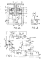
- FIG. 4A A preferred exemplary embodiment for such a regulated submicron positioning system, which at the same time comprises a third exemplary embodiment for the actuating element according to the invention, is shown in FIG. 4A.
- the positioning system of FIG. 4A essentially consists of an adjusting element 26 (upper part) and a displacement sensor 25 mechanically coupled therewith (lower part).
- Both parts are housed in a hollow cylindrical housing 21.
- the actuating element 26 comprises a magnetic pot system, which consists of the permanent magnet 2, an upper pot element 16 and a lower pot element 17. Between the two pot elements 16 and 17 there is an air gap arranged concentrically to the actuator axis.
- the air gap of the magnetic pot system is preferably filled with a highly viscous ferrofluid 18, e.g. used in speaker systems.
- the bobbin 3 is firmly seated on a cylindrical actuating rod 15, which is freely movable through the interior of the hollow cylindrical permanent magnet 2, and is resiliently connected to the housing 21 on both sides of the pot system via the springs 4, 4 ⁇ .
- a sample plate 14 is attached, on which a sample to be positioned can be fixed.
- the actuating rod 15 is connected to the optical displacement sensor 25, which comprises a measuring aperture 19, a transmitting diode DS (infrared LED), a measuring diode (DM), a reference diode DR and a sensor carrier 20.
- the optical displacement sensor 25 comprises a measuring aperture 19, a transmitting diode DS (infrared LED), a measuring diode (DM), a reference diode DR and a sensor carrier 20.
- the orifice 19 is rigidly connected to the actuating rod 15.
- Measuring diode DM and reference diode DR are arranged side by side in the direction of displacement of the control element. Opposite them, and partially shaded by the orifice 19, is the transmitter diode DS. All diodes DS, DM and DR are rigidly mounted on a sensor carrier and connected to the housing 21 via it.
- the Transmitting diode DS is installed at the same level as the receiving measuring diode DM.
- the measuring diaphragm 19 extends into the gap formed so far that the measuring diode DM is approximately half covered with respect to the transmitting diode DS.
- the reference diode DR used to regulate the emission of the transmitter diode DS receives the full light intensity of the transmitter diode DS at every diaphragm position.
- the displacement sensor 25 constructed in this way now outputs an analog output signal as a function of the position of the measuring orifice 19 and thus as a function of the position of the actuating element 26, which can be amplified and used to regulate the actuating element.
- the control electronics are connected to the displacement sensor 25 and its diodes DS, DM and DR.
- Two operational amplifiers V1 and V2 and their wiring with the resistors R1, ..., R5 and capacitors C1, C2 together with the reference diode DR and the transmitter diode DS form a PI control loop, which compensates both the temperature response of the transmitter diode and the temperature response of the Diodes DM and DR, which are preferably formed as photodiode segments on a common silicon substrate (eg in the form of the diode type BPX 48), optimally compensates.
- This actual value is included in the downstream PID controller (operational amplifier V4, resistors R9, ..., R13, capacitor C4) compared to an analog setpoint present at a setpoint input 22.
- a high level of accuracy in the control electronics is achieved by using a reference element 24 (together with the resistor R6) (for example of the type LM 399), which emits a stable reference voltage U ref , which is used as the reference voltage both for the operational amplifier V2 and for setting the zero position (via the resistors R7, R14) is used.
- a reference element 24 (together with the resistor R6) (for example of the type LM 399), which emits a stable reference voltage U ref , which is used as the reference voltage both for the operational amplifier V2 and for setting the zero position (via the resistors R7, R14) is used.
- the operational amplifiers V1, ..., V4 can, for example, be integrated in a single, inexpensive quadruple OP-AMP of the type LM 324 or LM 347.
- all components used in control electronics are available as so-called SMDs ( S urface M ounted D evices), so that the entire circuit can be built up on a few cm2 and built directly into the housing 21 of the positioning system.
- the invention provides an actuating element which is small, simple and inexpensive, can be operated electrically and has a large working area with high resolution at the same time.
Landscapes
- Physics & Mathematics (AREA)
- Engineering & Computer Science (AREA)
- Electromagnetism (AREA)
- Power Engineering (AREA)
- General Physics & Mathematics (AREA)
- Optics & Photonics (AREA)
- Chemical & Material Sciences (AREA)
- Combustion & Propulsion (AREA)
- Reciprocating, Oscillating Or Vibrating Motors (AREA)
- Control Of Position Or Direction (AREA)
Applications Claiming Priority (2)
| Application Number | Priority Date | Filing Date | Title |
|---|---|---|---|
| DE3626254 | 1986-08-02 | ||
| DE19863626254 DE3626254A1 (de) | 1986-08-02 | 1986-08-02 | Elektromagnetisches stellelement |
Publications (2)
| Publication Number | Publication Date |
|---|---|
| EP0258569A2 true EP0258569A2 (fr) | 1988-03-09 |
| EP0258569A3 EP0258569A3 (fr) | 1990-03-07 |
Family
ID=6306588
Family Applications (1)
| Application Number | Title | Priority Date | Filing Date |
|---|---|---|---|
| EP87109603A Withdrawn EP0258569A3 (fr) | 1986-08-02 | 1987-07-03 | Dispositif de positionnement électromagnétique |
Country Status (2)
| Country | Link |
|---|---|
| EP (1) | EP0258569A3 (fr) |
| DE (1) | DE3626254A1 (fr) |
Cited By (16)
| Publication number | Priority date | Publication date | Assignee | Title |
|---|---|---|---|---|
| EP0596301A1 (fr) * | 1992-11-01 | 1994-05-11 | Fraunhofer-Gesellschaft Zur Förderung Der Angewandten Forschung E.V. | Dispositif d'ajustage d'éléments optiques, notamment pour fabriquer un polygone à miroirs multiples |
| WO1997008806A1 (fr) * | 1995-08-29 | 1997-03-06 | Sidey Roger C H | Moteur electrique |
| FR2788163A1 (fr) * | 1998-12-30 | 2000-07-07 | Sextant Avionique | Actionneur electromagnetique equipe de moyens d'ajustement de la position de son element polaire mobile |
| WO2001021296A1 (fr) * | 1999-09-23 | 2001-03-29 | Siat Gmbh | Mecanisme multidimensionnel destine a des machines de travail |
| US6442851B1 (en) | 2001-05-21 | 2002-09-03 | Aerotech, Inc. | Direct drive tilt and goniometer stage |
| WO2002069479A1 (fr) * | 2001-02-27 | 2002-09-06 | Bei Technologies, Inc. | Actionneur de bobine mobile lineaire a course allongee dote d'une caracteristique de type solenoide proportionnel |
| US6607305B2 (en) * | 2001-06-04 | 2003-08-19 | Wisconsin Alumni Research Foundation | Bi-directional micromechanical latching linear actuator |
| EP1677133A1 (fr) * | 2004-12-30 | 2006-07-05 | Rohm and Haas Electronic Materials, L.L.C. | Support de microcomposant et procédé de fabrication correspondant |
| US20130136400A1 (en) * | 2011-11-28 | 2013-05-30 | Micah C. Isenhour | Optical couplings having a coded magnetic array, and connector assemblies and electronic devices having the same |
| WO2014056487A3 (fr) * | 2012-10-12 | 2014-06-12 | Rhefor Gbr | Entraînement linéaire électromagnétique hautement dynamique modulable à course limitée et présentant de faibles forces transversales |
| US9151900B2 (en) | 2010-12-07 | 2015-10-06 | Corning Optical Communications LLC | Optical couplings having coded magnetic arrays and devices incorporating the same |
| US9261651B2 (en) | 2010-12-07 | 2016-02-16 | Corning Optical Communications LLC | Ferrule assemblies, connector assemblies, and optical couplings having coded magnetic arrays |
| WO2016139076A1 (fr) * | 2015-03-05 | 2016-09-09 | Olympus Winter & Ibe Gmbh | Moteur pas à pas électrique rotatif et endoscope |
| EP2954541B1 (fr) * | 2013-02-11 | 2018-11-21 | Rausch & Pausch GmbH | Actionneur linéaire |
| US10191228B2 (en) | 2014-09-23 | 2019-01-29 | Corning Optical Communications LLC | Optical connectors and complimentary optical receptacles having magnetic attachment |
| CN110111971A (zh) * | 2019-06-14 | 2019-08-09 | 哈尔滨工业大学 | 基于弹簧压力和磁吸力实现位置稳定的双向自保持电磁铁 |
Families Citing this family (4)
| Publication number | Priority date | Publication date | Assignee | Title |
|---|---|---|---|---|
| DE19723515C2 (de) * | 1997-06-05 | 2002-08-01 | Deutsch Zentr Luft & Raumfahrt | Elastische Anordnung zum Führen von zwei elastisch verbundenen Bauteilen in einer Bewegungsrichtung |
| DE20219398U1 (de) * | 2002-12-13 | 2003-03-06 | Gesellschaft zur Förderung angewandter Optik, Optoelektronik, Quantenelektronik und Spektroskopie e.V., 12489 Berlin | Stellmotor für axiale Stellbewegungen |
| DE102010000582A1 (de) * | 2010-02-26 | 2011-09-01 | Karl Storz Gmbh & Co. Kg | Linearmotor mit permanentmagnetischer Selbsthaltung |
| DE102011080065B4 (de) * | 2010-10-16 | 2012-10-31 | Msm Krystall Gbr (Vertretungsberechtigte Gesellschafter: Dr. Rainer Schneider, 12165 Berlin; Arno Mecklenburg, 10999 Berlin) | Elektromagnetischer Linearaktor |
Family Cites Families (12)
| Publication number | Priority date | Publication date | Assignee | Title |
|---|---|---|---|---|
| DE463160C (de) * | 1927-04-24 | 1928-07-23 | Paul Rinkel Dipl Ing | Tellerfeder |
| DE845676C (de) * | 1948-10-02 | 1952-08-04 | Julius Dipl-Ing Lorenz | System zur Umwandlung von Schwingungen |
| DE1189755B (de) * | 1963-03-08 | 1965-03-25 | Telefunken Patent | Geraet mit mindestens einer lichtleitenden Faser |
| DE1212363B (de) * | 1963-12-06 | 1966-03-10 | Stromag Maschf | Als Rueckstellfeder wirkende Scheiben- oder Tellerfeder fuer die Ankerscheibe einer elektromagnetisch betaetigten Kupplung oder Bremse |
| BE755957A (fr) * | 1969-09-29 | 1971-02-15 | Euratom | |
| DE2056989A1 (de) * | 1970-11-20 | 1972-06-29 | Manger J | Elektromagnetische Verstellvorrichtung |
| GB2089132B (en) * | 1980-11-05 | 1984-07-18 | Hitachi Metals Ltd | Electromagnetic actuator |
| JPS5829754U (ja) * | 1981-08-21 | 1983-02-26 | 日立金属株式会社 | ドアロツク用アクチユエ−タ |
| US4475033A (en) * | 1982-03-08 | 1984-10-02 | Northern Telecom Limited | Positioning device for optical system element |
| DE3239153A1 (de) * | 1982-10-22 | 1984-04-26 | Bosch Gmbh Robert | Hubmagnet |
| US4560967A (en) * | 1984-04-04 | 1985-12-24 | Parker-Hannifin Corporation | Force motor |
| DE3426688A1 (de) * | 1984-07-19 | 1986-01-23 | Siemens Ag | Antriebsanordnung |
-
1986
- 1986-08-02 DE DE19863626254 patent/DE3626254A1/de not_active Withdrawn
-
1987
- 1987-07-03 EP EP87109603A patent/EP0258569A3/fr not_active Withdrawn
Cited By (24)
| Publication number | Priority date | Publication date | Assignee | Title |
|---|---|---|---|---|
| EP0596301A1 (fr) * | 1992-11-01 | 1994-05-11 | Fraunhofer-Gesellschaft Zur Förderung Der Angewandten Forschung E.V. | Dispositif d'ajustage d'éléments optiques, notamment pour fabriquer un polygone à miroirs multiples |
| WO1997008806A1 (fr) * | 1995-08-29 | 1997-03-06 | Sidey Roger C H | Moteur electrique |
| US5952743A (en) * | 1995-08-29 | 1999-09-14 | Sidey; Roger Charles Hey | Electric motor |
| US6556114B1 (en) | 1998-12-30 | 2003-04-29 | Thales Avionics S.A. | Electromagnetic actuator equipped with means for adjusting its mobile polar element |
| WO2000041189A1 (fr) * | 1998-12-30 | 2000-07-13 | Thales Avionics S.A. | Actionneur electromagnetique equipe de moyens d'ajustement de la position de son element polaire mobile |
| FR2788163A1 (fr) * | 1998-12-30 | 2000-07-07 | Sextant Avionique | Actionneur electromagnetique equipe de moyens d'ajustement de la position de son element polaire mobile |
| WO2001021296A1 (fr) * | 1999-09-23 | 2001-03-29 | Siat Gmbh | Mecanisme multidimensionnel destine a des machines de travail |
| WO2002069479A1 (fr) * | 2001-02-27 | 2002-09-06 | Bei Technologies, Inc. | Actionneur de bobine mobile lineaire a course allongee dote d'une caracteristique de type solenoide proportionnel |
| US6442851B1 (en) | 2001-05-21 | 2002-09-03 | Aerotech, Inc. | Direct drive tilt and goniometer stage |
| EP1260305A1 (fr) * | 2001-05-21 | 2002-11-27 | Aerotech, Inc. | Table basculante et goniométrique d'entrainement direct |
| US6607305B2 (en) * | 2001-06-04 | 2003-08-19 | Wisconsin Alumni Research Foundation | Bi-directional micromechanical latching linear actuator |
| EP1677133A1 (fr) * | 2004-12-30 | 2006-07-05 | Rohm and Haas Electronic Materials, L.L.C. | Support de microcomposant et procédé de fabrication correspondant |
| US9151900B2 (en) | 2010-12-07 | 2015-10-06 | Corning Optical Communications LLC | Optical couplings having coded magnetic arrays and devices incorporating the same |
| US9261651B2 (en) | 2010-12-07 | 2016-02-16 | Corning Optical Communications LLC | Ferrule assemblies, connector assemblies, and optical couplings having coded magnetic arrays |
| US20130136400A1 (en) * | 2011-11-28 | 2013-05-30 | Micah C. Isenhour | Optical couplings having a coded magnetic array, and connector assemblies and electronic devices having the same |
| US8734024B2 (en) * | 2011-11-28 | 2014-05-27 | Corning Cable Systems Llc | Optical couplings having a coded magnetic array, and connector assemblies and electronic devices having the same |
| US9547139B2 (en) | 2011-11-28 | 2017-01-17 | Corning Optical Communications LLC | Optical couplings having a coded magnetic array, and connector assemblies and electronic devices having the same |
| WO2014056487A3 (fr) * | 2012-10-12 | 2014-06-12 | Rhefor Gbr | Entraînement linéaire électromagnétique hautement dynamique modulable à course limitée et présentant de faibles forces transversales |
| US10320276B2 (en) | 2012-10-12 | 2019-06-11 | Rhefor Gbr | Scalable, highly dynamic electromagnetic linear drive with limited travel and low transverse forces |
| EP2954541B1 (fr) * | 2013-02-11 | 2018-11-21 | Rausch & Pausch GmbH | Actionneur linéaire |
| US10191228B2 (en) | 2014-09-23 | 2019-01-29 | Corning Optical Communications LLC | Optical connectors and complimentary optical receptacles having magnetic attachment |
| WO2016139076A1 (fr) * | 2015-03-05 | 2016-09-09 | Olympus Winter & Ibe Gmbh | Moteur pas à pas électrique rotatif et endoscope |
| CN110111971A (zh) * | 2019-06-14 | 2019-08-09 | 哈尔滨工业大学 | 基于弹簧压力和磁吸力实现位置稳定的双向自保持电磁铁 |
| CN110111971B (zh) * | 2019-06-14 | 2021-10-15 | 哈尔滨工业大学 | 基于弹簧压力和磁吸力实现位置稳定的双向自保持电磁铁 |
Also Published As
| Publication number | Publication date |
|---|---|
| EP0258569A3 (fr) | 1990-03-07 |
| DE3626254A1 (de) | 1988-02-11 |
Similar Documents
| Publication | Publication Date | Title |
|---|---|---|
| DE3854128T2 (de) | Mikropositioniersysteme und -verfahren. | |
| DE3626254A1 (de) | Elektromagnetisches stellelement | |
| DE69218417T2 (de) | Lagerung für einen beweglichen spiegel eines michelsoninterferometers | |
| EP0147610A2 (fr) | Commutateur à guide d'ondes | |
| EP0286722B1 (fr) | Régulateur de position électropneumatique | |
| DE69210110T2 (de) | Strahlabtast-Galvanometer mit Spiegel und Magnet von geringer Trägheit | |
| DE2010583A1 (de) | Druckmessgerät | |
| DE69005689T2 (de) | Mechanische Objektplatte, insbesondere für ein Tunneleffektmikroskop. | |
| DE4210741A1 (de) | Magnetische Lagerung für schwebenden Körper | |
| DE19649515B4 (de) | Verfahren und Vorrichtung zur Messung der Dicke dünner Schichten sowie Schaltung zur Ansteuerung der Vorrichtung | |
| DE69307833T2 (de) | Probenträgervorrichtung für ein Rastermikroskop | |
| DE68915751T2 (de) | Vorrichtung zur Erzeugung eines Magnetfeldes für ein Elektronspinresonanzsystem. | |
| DE3415419A1 (de) | Taster fuer ein zahnflankenprofilmessgeraet zur ermittlung der zahnflankenoberflaechenrauheit | |
| DE3738106A1 (de) | Vorrichtung fuer ein haertemessgeraet | |
| DE3104379A1 (de) | Druckmesser mit elektro-mechanischem wandler | |
| EP1639690B1 (fr) | Mecanisme d'entrainement direct plan comprenant un systeme de mesure de position | |
| DE3802145C1 (en) | Optoelectrical device | |
| DE2810257C2 (de) | Elektropneumatischer Strom/Stellung-Wandler | |
| DE4108688A1 (de) | Vorrichtung zum positionieren eines objektes | |
| EP1321792A1 (fr) | Procédé et methode pour contrôler la position d'un rayon laser et actionneur | |
| DE947095C (de) | Kompensationsverstaerker fuer elektrische Spannungsmessungen mit lichtelektrischer Steuerung und Roehrenverstaerkung | |
| DE2150118A1 (de) | Solenoid-Einrichtung | |
| EP1037009B1 (fr) | Positionneur pour un microscope à sonde de balayage | |
| DE3441728A1 (de) | Hohlleiterschalter | |
| DE3874818T2 (de) | Linearer schrittmotor. |
Legal Events
| Date | Code | Title | Description |
|---|---|---|---|
| PUAI | Public reference made under article 153(3) epc to a published international application that has entered the european phase |
Free format text: ORIGINAL CODE: 0009012 |
|
| AK | Designated contracting states |
Kind code of ref document: A2 Designated state(s): CH DE FR GB LI |
|
| PUAL | Search report despatched |
Free format text: ORIGINAL CODE: 0009013 |
|
| RHK1 | Main classification (correction) |
Ipc: G02B 6/32 |
|
| AK | Designated contracting states |
Kind code of ref document: A3 Designated state(s): CH DE FR GB LI |
|
| 17P | Request for examination filed |
Effective date: 19900806 |
|
| STAA | Information on the status of an ep patent application or granted ep patent |
Free format text: STATUS: THE APPLICATION IS DEEMED TO BE WITHDRAWN |
|
| 18D | Application deemed to be withdrawn |
Effective date: 19920201 |
|
| RIN1 | Information on inventor provided before grant (corrected) |
Inventor name: SCHAD,HANSPETER,DR. Inventor name: HEIMGARTNER, DIETER Inventor name: WIDMER,STEFAN Inventor name: KAUFMANN, MEINOLPH |