EP2954541B1 - Actionneur linéaire - Google Patents
Actionneur linéaire Download PDFInfo
- Publication number
- EP2954541B1 EP2954541B1 EP14703403.7A EP14703403A EP2954541B1 EP 2954541 B1 EP2954541 B1 EP 2954541B1 EP 14703403 A EP14703403 A EP 14703403A EP 2954541 B1 EP2954541 B1 EP 2954541B1
- Authority
- EP
- European Patent Office
- Prior art keywords
- linear actuator
- magnetic armature
- actuator according
- armature
- actuator
- Prior art date
- Legal status (The legal status is an assumption and is not a legal conclusion. Google has not performed a legal analysis and makes no representation as to the accuracy of the status listed.)
- Not-in-force
Links
Images

Classifications
-
- H—ELECTRICITY
- H02—GENERATION; CONVERSION OR DISTRIBUTION OF ELECTRIC POWER
- H02K—DYNAMO-ELECTRIC MACHINES
- H02K41/00—Propulsion systems in which a rigid body is moved along a path due to dynamo-electric interaction between the body and a magnetic field travelling along the path
- H02K41/02—Linear motors; Sectional motors
-
- H—ELECTRICITY
- H02—GENERATION; CONVERSION OR DISTRIBUTION OF ELECTRIC POWER
- H02K—DYNAMO-ELECTRIC MACHINES
- H02K33/00—Motors with reciprocating, oscillating or vibrating magnet, armature or coil system
- H02K33/16—Motors with reciprocating, oscillating or vibrating magnet, armature or coil system with polarised armatures moving in alternate directions by reversal or energisation of a single coil system
-
- B—PERFORMING OPERATIONS; TRANSPORTING
- B60—VEHICLES IN GENERAL
- B60K—ARRANGEMENT OR MOUNTING OF PROPULSION UNITS OR OF TRANSMISSIONS IN VEHICLES; ARRANGEMENT OR MOUNTING OF PLURAL DIVERSE PRIME-MOVERS IN VEHICLES; AUXILIARY DRIVES FOR VEHICLES; INSTRUMENTATION OR DASHBOARDS FOR VEHICLES; ARRANGEMENTS IN CONNECTION WITH COOLING, AIR INTAKE, GAS EXHAUST OR FUEL SUPPLY OF PROPULSION UNITS IN VEHICLES
- B60K5/00—Arrangement or mounting of internal-combustion or jet-propulsion units
- B60K5/12—Arrangement of engine supports
- B60K5/1283—Adjustable supports, e.g. the mounting or the characteristics being adjustable
-
- F—MECHANICAL ENGINEERING; LIGHTING; HEATING; WEAPONS; BLASTING
- F16—ENGINEERING ELEMENTS AND UNITS; GENERAL MEASURES FOR PRODUCING AND MAINTAINING EFFECTIVE FUNCTIONING OF MACHINES OR INSTALLATIONS; THERMAL INSULATION IN GENERAL
- F16C—SHAFTS; FLEXIBLE SHAFTS; ELEMENTS OR CRANKSHAFT MECHANISMS; ROTARY BODIES OTHER THAN GEARING ELEMENTS; BEARINGS
- F16C32/00—Bearings not otherwise provided for
- F16C32/04—Bearings not otherwise provided for using magnetic or electric supporting means
- F16C32/0406—Magnetic bearings
- F16C32/044—Active magnetic bearings
- F16C32/0472—Active magnetic bearings for linear movement
-
- H—ELECTRICITY
- H01—ELECTRIC ELEMENTS
- H01F—MAGNETS; INDUCTANCES; TRANSFORMERS; SELECTION OF MATERIALS FOR THEIR MAGNETIC PROPERTIES
- H01F7/00—Magnets
- H01F7/06—Electromagnets; Actuators including electromagnets
- H01F7/08—Electromagnets; Actuators including electromagnets with armatures
- H01F7/16—Rectilinearly-movable armatures
- H01F7/1607—Armatures entering the winding
-
- H—ELECTRICITY
- H02—GENERATION; CONVERSION OR DISTRIBUTION OF ELECTRIC POWER
- H02K—DYNAMO-ELECTRIC MACHINES
- H02K1/00—Details of the magnetic circuit
- H02K1/06—Details of the magnetic circuit characterised by the shape, form or construction
- H02K1/22—Rotating parts of the magnetic circuit
- H02K1/28—Means for mounting or fastening rotating magnetic parts on to, or to, the rotor structures
- H02K1/30—Means for mounting or fastening rotating magnetic parts on to, or to, the rotor structures using intermediate parts, e.g. spiders
-
- F—MECHANICAL ENGINEERING; LIGHTING; HEATING; WEAPONS; BLASTING
- F16—ENGINEERING ELEMENTS AND UNITS; GENERAL MEASURES FOR PRODUCING AND MAINTAINING EFFECTIVE FUNCTIONING OF MACHINES OR INSTALLATIONS; THERMAL INSULATION IN GENERAL
- F16C—SHAFTS; FLEXIBLE SHAFTS; ELEMENTS OR CRANKSHAFT MECHANISMS; ROTARY BODIES OTHER THAN GEARING ELEMENTS; BEARINGS
- F16C32/00—Bearings not otherwise provided for
- F16C32/04—Bearings not otherwise provided for using magnetic or electric supporting means
- F16C32/0406—Magnetic bearings
- F16C32/044—Active magnetic bearings
- F16C32/0459—Details of the magnetic circuit
- F16C32/0468—Details of the magnetic circuit of moving parts of the magnetic circuit, e.g. of the rotor
-
- F—MECHANICAL ENGINEERING; LIGHTING; HEATING; WEAPONS; BLASTING
- F16—ENGINEERING ELEMENTS AND UNITS; GENERAL MEASURES FOR PRODUCING AND MAINTAINING EFFECTIVE FUNCTIONING OF MACHINES OR INSTALLATIONS; THERMAL INSULATION IN GENERAL
- F16F—SPRINGS; SHOCK-ABSORBERS; MEANS FOR DAMPING VIBRATION
- F16F13/00—Units comprising springs of the non-fluid type as well as vibration-dampers, shock-absorbers, or fluid springs
-
- F—MECHANICAL ENGINEERING; LIGHTING; HEATING; WEAPONS; BLASTING
- F16—ENGINEERING ELEMENTS AND UNITS; GENERAL MEASURES FOR PRODUCING AND MAINTAINING EFFECTIVE FUNCTIONING OF MACHINES OR INSTALLATIONS; THERMAL INSULATION IN GENERAL
- F16F—SPRINGS; SHOCK-ABSORBERS; MEANS FOR DAMPING VIBRATION
- F16F13/00—Units comprising springs of the non-fluid type as well as vibration-dampers, shock-absorbers, or fluid springs
- F16F13/04—Units comprising springs of the non-fluid type as well as vibration-dampers, shock-absorbers, or fluid springs comprising both a plastics spring and a damper, e.g. a friction damper
- F16F13/06—Units comprising springs of the non-fluid type as well as vibration-dampers, shock-absorbers, or fluid springs comprising both a plastics spring and a damper, e.g. a friction damper the damper being a fluid damper, e.g. the plastics spring not forming a part of the wall of the fluid chamber of the damper
- F16F13/08—Units comprising springs of the non-fluid type as well as vibration-dampers, shock-absorbers, or fluid springs comprising both a plastics spring and a damper, e.g. a friction damper the damper being a fluid damper, e.g. the plastics spring not forming a part of the wall of the fluid chamber of the damper the plastics spring forming at least a part of the wall of the fluid chamber of the damper
- F16F13/14—Units of the bushing type, i.e. loaded predominantly radially
- F16F13/149—Multiple bushings connected together; Restraining links
-
- F—MECHANICAL ENGINEERING; LIGHTING; HEATING; WEAPONS; BLASTING
- F16—ENGINEERING ELEMENTS AND UNITS; GENERAL MEASURES FOR PRODUCING AND MAINTAINING EFFECTIVE FUNCTIONING OF MACHINES OR INSTALLATIONS; THERMAL INSULATION IN GENERAL
- F16F—SPRINGS; SHOCK-ABSORBERS; MEANS FOR DAMPING VIBRATION
- F16F13/00—Units comprising springs of the non-fluid type as well as vibration-dampers, shock-absorbers, or fluid springs
- F16F13/04—Units comprising springs of the non-fluid type as well as vibration-dampers, shock-absorbers, or fluid springs comprising both a plastics spring and a damper, e.g. a friction damper
- F16F13/26—Units comprising springs of the non-fluid type as well as vibration-dampers, shock-absorbers, or fluid springs comprising both a plastics spring and a damper, e.g. a friction damper characterised by adjusting or regulating devices responsive to exterior conditions
-
- F—MECHANICAL ENGINEERING; LIGHTING; HEATING; WEAPONS; BLASTING
- F16—ENGINEERING ELEMENTS AND UNITS; GENERAL MEASURES FOR PRODUCING AND MAINTAINING EFFECTIVE FUNCTIONING OF MACHINES OR INSTALLATIONS; THERMAL INSULATION IN GENERAL
- F16F—SPRINGS; SHOCK-ABSORBERS; MEANS FOR DAMPING VIBRATION
- F16F5/00—Liquid springs in which the liquid works as a spring by compression, e.g. combined with throttling action; Combinations of devices including liquid springs
-
- H—ELECTRICITY
- H01—ELECTRIC ELEMENTS
- H01F—MAGNETS; INDUCTANCES; TRANSFORMERS; SELECTION OF MATERIALS FOR THEIR MAGNETIC PROPERTIES
- H01F7/00—Magnets
- H01F7/06—Electromagnets; Actuators including electromagnets
- H01F7/08—Electromagnets; Actuators including electromagnets with armatures
- H01F7/081—Magnetic constructions
- H01F2007/086—Structural details of the armature
Definitions
- the present invention relates to a linear actuator, in particular for use in an active engine mount of a vehicle.
- active engine mounts can be used to improve comfort.
- unwanted vibrations and thereby caused noise transmission into the interior of the vehicle can be suppressed or at least reduced.
- Unwanted vibrations may occur, for example, in a cylinder deactivation of the engine, when one or more of the cylinders of the engine are turned off, the engine can run rough.
- An active engine mount for this purpose has a control for one or more actuators, in order to counteract the vibrations of the motor by means of the actuators in a manner familiar to those skilled in the art.
- the actuators can in particular be linear actuators which are operated electromagnetically.
- a linear actuator usually has a stator with an electrically energizable coil for generating an electromagnetic field and an axially movable with respect to the stator mounted actuator with a magnet armature.
- the actuator also has an axially extending ram for actuating the active engine mount. It is advantageous to mount the actuator in the stator, for example by means of a spring element, in such a way that it can be moved axially without friction.
- EP 0 181 056 A shows a switching magnet arrangement, wherein the actuator is axially movably mounted in a cylindrical Magentraum formed by a stator, wherein the actuator has a support element made of aluminum or plastic for a plunger and against the plunger axially to a solid magnetically filling the magnetic space magnet armature bordered by interlocking complementary conical surfaces.
- EP0258568 shows an electromagnetic actuator consisting of a coaxial in a hollow cylindrical permanent magnet combination of bobbin and coil winding.
- the bobbin is supported at both ends by disc-shaped springs.
- the actuator comprises a carrier element which extends in the radial direction between the armature and the plunger.
- the support member is made of a non-magnetic material having a lower density than the armature.
- the armature thus does not reach up to the plunger zoom, but is supported by a support member which may be formed in an advantageous lightweight construction.
- the weight of the actuator can be reduced, which has a positive effect on the behavior of the linear actuator even at high frequency vibrations.
- the reduced mass inertia of the actuator improves the response, since in particular in a reversal of the energization of the coil, the inversion of the actuator is reduced.
- the invention is based on the finding that the spatial extent of the magnet armature, which consists of a relatively heavy magnetic material, can be reduced without this having a significant effect on the magnetic force acting on the magnet armature. Therefore, the radially inner part of the actuator can be replaced by a non-magnetic, lighter material. Because it has unexpectedly been found that run in this area almost no field lines of the electromagnetic field of the coil. This means that in this area at most an unordered leakage flux of the magnetic field occurs, which, however, has no influence on the magnetic force. The relevant field lines run in a closed circle in the iron circle of the linear actuator, in particular by the magnet armature.
- the magnet armature and the carrier element are therefore preferably dimensioned such that an enlargement of the magnet armature in the radial direction does not increase or at least substantially increase, for example a maximum of 5%, of the operation generated by the electromagnetic field and acting on the actuator Magnetic force would cause.
- the spatial extent and the mass of the armature are reduced to a minimum in a given structure of the stator and a predetermined current level, with which the coil is energized. It is not necessary to increase the magnet armature radially inwardly in the direction of the plunger and to reduce the carrier element accordingly, since, as explained, no relevant field lines of the electromagnetic field run in this region. The relevant field lines pass through the magnet armature.
- the armature is thus reduced to its magnetically relevant volume.
- a further reduction of the magnet armature would lead to a throttling of the magnetic field and to a negative influence on the field lines, which would result in a reduction of the magnetic force.
- the armature is annular and surrounds the carrier element.
- the armature thus occupies that part of the actuator which is adjacent to the coil and therefore particularly relevant to the action of the magnetic field.
- the annular magnet armature is formed as narrow as possible, wherein the ratio of the outer diameter of the magnet armature to the inner diameter of the magnet armature is at most 2: 1, preferably at most 1.5: 1 and more preferably at most 1.25: 1.
- the magnet armature thus preferably occupies at most half, more preferably at most one third and even more preferably at most one fifth.
- the cross section of the armature tapers inwardly in the axial direction.
- the shape of the cross section of the magnet armature can be used to reduce the volume of the armature, without negatively affecting the force balance of the magnetic force.
- the cross section of the magnet armature can be reduced from radially inward, wherein the field lines of the electromagnetic field are not disturbed.
- one corner or two corners can be removed from radially inward so that, for example, an approximately trapezoidal cross-section is created.
- Other radially inwardly tapering cross-sectional shapes are also possible, such as a trapezoidal shape with rounded corners, a round shape or even a concave shape, as long as the course of the field lines is not hindered by the armature.
- the carrier element comprises a lightweight construction material or substantially completely consists thereof, such as aluminum, magnesium, plastic and / or a fiber composite material.
- the actuator comprises at least one permanent magnet which adjoins the magnet armature and is preferably arranged on the outer circumference of the magnet armature.
- two permanent magnets spaced apart in the axial direction and preferably magnetized in the radial direction may be provided.
- the permanent magnets which may also be referred to as permanent magnets, are of particular importance when the iron circle of the linear actuator does not comprise a stationary pole part or a direction of movement of the actuator which depends on the polarity of the exciting current is desired.
- the axial displacement of the actuator is then caused by the force acting on the armature magnetic force of the magnetic field, which is composed of the electromagnetic field of the energized coil and the magnetic field of the permanent magnet.
- the carrier element has openings and can preferably at least partially in the axial direction a smaller
- the support member may also have recesses to save weight. These measures serve to further reduce the volume and thus the mass of the support element.
- the extent, the arrangement, the configuration and the shape of the perforations and / or recesses in the carrier element are dependent in particular on the material used of the carrier element and also on the application of magnetic forces, in such a way that the mechanical stability of the carrier element is not affected is.
- the openings may have any shape and extend in the axial direction. It is also possible not to provide completely through the support member passing through openings, but only to form recesses on one or both axial sides of the support member.
- the carrier element has a magnet armature bearing radially outer part and a ram supporting radially inner part, which are connected to each other via spoke-like webs.
- the carrier element can be designed like a rim and the magnet armature can be seated on the outer circumference of the carrier element.
- the carrier element may comprise at least one deep-drawn part, which allows a particularly simple and cost-effective production.
- the actuator is mounted in the stator by means of at least one spring element such that it can be moved axially without friction when the coil is energized.
- the actuator is coupled on opposite axial sides of the armature respectively via at least one spring element with the stator such that the actuator is radially aligned by means of the spring elements with respect to the stator.
- the at least one spring element for radial alignment is advantageously the same spring element as for frictionless mounting.
- the spring elements can exert defined restoring forces on the actuator, so that the stiffness of the linear actuator can be adjusted by suitable choice of the spring geometry and the spring thickness without For example, additional compression springs are necessary.
- spring elements are used, which are flat in the relaxed state and extend in a plane perpendicular to the direction of movement of the magnet armature.
- the spring elements can be cut out of a sheet-like material, preferably stamped out, and thus as a tool-falling part, for example as a cut part, can be produced easily and inexpensively. The production by laser cutting or by etching is also possible.
- the frictionless mounting of the actuator has the advantage that no frictional forces occur and thereby mechanical stress on the actuator is avoided. Furthermore, no hysteresis is generated by friction, so that only a magnetic hysteresis remains.
- the lack of friction improves the response of the linear actuator, i. in the event of a change in the reference signal, in particular a reversal of the electrical current, a change in the actuating signal takes place without delay, i. the force generated or the path traveled by the actuator. In characteristic curves, this behavior can be recognized by a sharp reversal of the output signal when the command signal is reversed. Dead times at the reversal points are thus avoided.
- the linear actuator is preferably used in an engine mount for an engine of a vehicle to counteract vibrations of the engine mount.
- a control for the linear actuator is provided, which controls the linear actuator in a suitable manner.
- the engine mount may include an oil-filled volume on which the engine is mounted.
- the plunger of the linear actuator is coupled to a diaphragm adjacent to the oil volume so that the volume of oil can be excited at a frequency received by a sensor to dampen the vibrations of the engine through the corresponding oscillations of the oil volume.
- a linear actuator for an active engine mount of a motor vehicle is shown.
- the linear actuator has a stationary stator 2, which comprises an electrically energizable coil 5. Furthermore, an electrical connection 10 is provided, via which the linear actuator is supplied with current.
- an actuator 1 is mounted with a plunger 8 via two spring elements 6 axially movable and radially aligned.
- the spring elements 6 are designed such that the actuator 1 is mounted without friction. That is, between the stator 2 and the actuator 1 is preferably an air gap, which is maintained by the storage of the actuator 1 by means of the spring elements 6 even during the axial movement of the actuator 1.
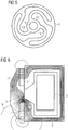
- One of the spring elements 6 is in Fig. 5 shown in plan view.
- the spring element 6 is formed substantially flat and has curved, here substantially S-shaped, struts 13, which provide for the radial alignment of the actuator 1.
- the radial stiffness of the spring element 6 is high in comparison to its axial rigidity, so that the radial alignment is ensured even with an axial movement.
- the actuator 1 comprises a magnet armature 3 and a carrier element 4, which is arranged between the armature 3 and the plunger 8.
- the plunger 8 is in a bore 9 (see Fig. 2a . 3 ) of the carrier element 4, but may also be formed with the carrier element 4 as an integral component.
- the plunger 8 serves to connect the linear actuator to surrounding components of the engine mount. Since the linear actuator does not have a fixed pole part, two permanent magnets 7 are provided radially on the outside so that a magnetic force is generated in the axial direction by generating an electromagnetic field through the coil 5 and the resulting magnetization of the magnet armature 3.
- the necessary magnetic force for displacement of the actuator 1 is effected by an interaction of the electromagnetically generated magnetic force and the magnetic force of the permanent magnet 7.
- the arrangement of the permanent magnet 7 in recesses of the magnet armature 3 also allows a compact design.
- the linear actuator is intended to influence by displacement of the plunger 8 other components of the engine mount so as to indirectly counteract vibrations of the engine of the motor vehicle, so that they are not transmitted to other body parts and in the interior of the vehicle.
- the linear actuator is excited dynamically with a frequency determined by a controller.
- the plunger is coupled to a membrane which limits an oil volume on which the engine is mounted and which is excited according to the vibration damping means of the linear actuator.
- the plunger 8 is inserted into the bore 9 of the support member 4 and projects through a central opening 14 of the spring elements. 6
- the mass of the actuator 1 is kept low, so that the resonant frequency of the actuator 1 is increased and inertia effects are reduced. Accordingly, the mass of the armature 3 are reduced to a minimum and the support member 4 made of a lightweight material, such as aluminum, magnesium, plastic or a fiber composite material, namely a material having a lower density than the material of the magnet armature 3.
- a lightweight material such as aluminum, magnesium, plastic or a fiber composite material
- the magnet armature 3 may have a radially inwardly tapering cross-sectional shape, as long as, as in Fig. 6 can be seen, the relevant field lines 15 extend substantially within the armature 3.
- Other cross-sectional shapes which satisfy this condition are also possible, for example rounded shapes.
- Fig. 2a the structure of the actuator 1 (without the plunger 8) is shown in section.
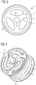
- Fig. 3 shows a plan view. It can be seen that the armature 3 is formed as an annular part of the actuator 1.
- the carrier element 4 is arranged radially inwardly with respect to the magnet armature 3.
- the support element 4 is here formed in two parts. In particular, by the beveled radially outer side of the support member 4 and the corresponding tapered shape of the armature 3 of the armature 3 can be easily held without additional fasteners.
- the weight of the support member 4 is further reduced by openings 12, and radial recesses 18 and axial recesses 17 are provided.
- the rim-like design of the support member 4 can be seen with its spoke-like webs 11, which connect a radially outer part 19 with a radially inner part 20.
- the radially outer part 19 carries the armature 3, while the radially inner part 20 carries the plunger 8.
- Other forms of the carrier element 4, in particular the perforations and recesses, are possible and can be selected depending on the load to be carried and the material used. It is also possible to provide no perforations and / or recesses.
- the armature 3 occupies only a small part of the actuator 1.
- the armature 3 may occupy less than 20%, preferably less than 10%, of the total diameter of the actuator 1.
- the magnet armature 3 may have an outer diameter of 47.4 mm and an inner diameter of 39.0 mm, so that the magnet armature 3 has a wall thickness of only 4.2 mm.
- the support member 4 ' is formed by two deep-drawn parts. There are two identical deep-drawn parts 4 'are provided, which face each other. Between the two parts of the armature 3 'is arranged, analogous to the two-part construction of in Fig. 2a illustrated carrier element. 4 In order to allow an exchange of fluid in the axial direction and also to further reduce weight, axial openings 12 'are provided. These are provided in both parts of the support member 4 ', wherein the parts of the support member 4' are aligned with each other so that the openings 12 'of the two parts coincide. Furthermore, the central bore 9 in the support member 4 ', in which the plunger 8 is supported, formed by deep drawing. The production of the carrier element 4 'in the deep drawing process is particularly simple and inexpensive.
Landscapes
- Engineering & Computer Science (AREA)
- Power Engineering (AREA)
- Physics & Mathematics (AREA)
- Electromagnetism (AREA)
- General Engineering & Computer Science (AREA)
- Mechanical Engineering (AREA)
- Chemical & Material Sciences (AREA)
- Combustion & Propulsion (AREA)
- Transportation (AREA)
- Arrangement Or Mounting Of Propulsion Units For Vehicles (AREA)
- Reciprocating, Oscillating Or Vibrating Motors (AREA)
- Vibration Prevention Devices (AREA)
Claims (14)
- Actionneur linéaire comprenant un stator (2) ayant une bobine (5) apte à être alimentée en courant pour la génération d'un champ électromagnétique (15) ainsi qu'un organe d'actionnement (1) logé en mobilité axiale par rapport au stator (2) et doté d'un armature d'aimant magnétique (3) et d'au moins un aimant permanent (7) adjacent à l'armature d'aimant (3), et un poussoir (8) s'étendant en direction axiale, cependant que l'organe d'actionnement (1) est, au moyen d'au moins un élément ressort (6), logé de telle manière dans le stator (2) qu'il est axialement déplaçable sans frottement quand la bobine (5) est alimentée en courant,
caractérisé en ce que l'organe d'actionnement (1) comprend un élément support (4) qui s'étend en direction radiale entre l'armature d'aimant (3) et le poussoir (8), cependant que l'élément support (4) consiste en un matériau amagnétique présentant une densité inférieure à celle de l'armature d'aimant (3), cependant que l'élément support (4) comporte une partie (19) radialement extérieure supportant l'armature d'aimant (3) et une partie (20) radialement intérieure supportant le poussoir (8), lesquelles sont reliées entre elles par l'intermédiaire de traverses (11) en forme de rayons. - Actionneur linéaire selon la revendication 1, cependant que l'armature d'aimant (3) et l'élément support (4) sont dimensionnés et conçus de telle façon qu'un agrandissement de l'armature d'aimant (3) en direction radiale vers l'intérieur n'engendrerait sensiblement pas d'augmentation de la force magnétique générée lors du fonctionnement par le champ magnétique (15) et agissant sur l'organe d'actionnement (1).
- Actionneur linéaire selon la revendication 1 ou 2, cependant que l'armature d'aimant (3) est réalisée sous forme annulaire et entoure l'élément support (4).
- Actionneur linéaire selon la revendication 3, caractérisé en ce que le rapport entre le diamètre extérieur de l'armature d'aimant (3) et le diamètre intérieur de l'armature d'aimant (3) est au maximum de 2:1, de préférence au maximum de 1,5:1, en outre de préférence au maximum de 1,25:1.
- Actionneur linéaire selon une des revendications de 1 à 4, cependant que la section transversale de l'armature d'aimant (3) s'effile vers l'intérieur en direction radiale.
- Actionneur linéaire selon une des revendications de 1 à 5, cependant que l'élément support (4) comprend de l'aluminium, du magnésium, de la matière plastique et/ou un matériau composite de fibres, ou en est essentiellement composé entièrement.
- Actionneur linéaire selon une des revendications de 1 à 6, cependant que le au moins un aimant permanent (7) est agencé sur la circonférence extérieure de l'armature d'aimant, cependant que, de préférence, deux aimants permanents (7) espacés en direction axiale sont prévus.
- Actionneur linéaire selon une des revendications de 1 à 7, cependant que l'élément support (4) comporte des transpercements (12) et présente, de préférence en direction axiale, au moins en certaines zones (17), une dimension inférieure à celle de l'armature d'aimant (3).
- Actionneur linéaire selon une des revendications de 1 à 8, cependant que l'élément support (4) comprend au moins une partie emboutie.
- Actionneur linéaire selon une des revendications de 1 à 9, cependant que l'organe d'actionnement (1) est, à des côtés axiaux opposés de l'armature d'aimant, respectivement couplé de telle façon avec le stator (2) par l'intermédiaire d'au moins un élément ressort (6) que l'organe d'actionnement (1) est, au moyen des éléments ressort (6), orienté radialement par rapport au stator (2).
- Actionneur linéaire selon la revendications 10, cependant que, à l'état détendu, les éléments ressort (6) sont plans et s'étendent dans un plan perpendiculairement à la direction du mouvement de l'organe d'actionnement (4).
- Actionneur linéaire selon la revendication 10 ou 11, cependant que les éléments ressort (6) sont découpés, de préférence estampés, à partir d'un matériau en forme de tôle.
- Palier de moteur destiné à un moteur d'un véhicule, comprenant au moins un actionneur linéaire selon une des revendications de 1 à 12 et une commande pour l'actionneur linéaire, la commande étant conçue pour contrecarrer des vibrations du palier de moteur par une commande appropriée de l'actionneur linéaire.
- Utilisation de l'actionneur linéaire selon une des revendications de 1 à 12 dans un palier de moteur pour un moteur d'un véhicule.
Applications Claiming Priority (2)
| Application Number | Priority Date | Filing Date | Title |
|---|---|---|---|
| DE102013202166.6A DE102013202166A1 (de) | 2013-02-11 | 2013-02-11 | Linearaktuator |
| PCT/EP2014/052566 WO2014122312A1 (fr) | 2013-02-11 | 2014-02-10 | Actionneur linéaire |
Publications (2)
| Publication Number | Publication Date |
|---|---|
| EP2954541A1 EP2954541A1 (fr) | 2015-12-16 |
| EP2954541B1 true EP2954541B1 (fr) | 2018-11-21 |
Family
ID=50070592
Family Applications (1)
| Application Number | Title | Priority Date | Filing Date |
|---|---|---|---|
| EP14703403.7A Not-in-force EP2954541B1 (fr) | 2013-02-11 | 2014-02-10 | Actionneur linéaire |
Country Status (4)
| Country | Link |
|---|---|
| US (1) | US10284068B2 (fr) |
| EP (1) | EP2954541B1 (fr) |
| DE (1) | DE102013202166A1 (fr) |
| WO (1) | WO2014122312A1 (fr) |
Families Citing this family (8)
| Publication number | Priority date | Publication date | Assignee | Title |
|---|---|---|---|---|
| DE102016203064A1 (de) | 2016-02-26 | 2017-08-31 | Robert Bosch Gmbh | Elektromagnetisches Lager mit einstellbarer Steifigkeit |
| US20180068459A1 (en) * | 2016-09-08 | 2018-03-08 | Ford Global Technologies, Llc | Object Distance Estimation Using Data From A Single Camera |
| WO2018142801A1 (fr) * | 2017-01-31 | 2018-08-09 | 住友理工株式会社 | Dispositif actif d'amortissement de vibrations |
| DE102017103027A1 (de) * | 2017-02-15 | 2018-08-16 | Rausch & Pausch Gmbh | Linearaktuator |
| DE102017120627A1 (de) | 2017-09-07 | 2019-03-07 | Rausch & Pausch Gmbh | Verfahren zur Herstellung eines Magnetanker-Stößel-Verbundes und Magnetanker-Stößel-Verbund für einen Linearaktuator |
| US11643169B2 (en) * | 2019-02-19 | 2023-05-09 | The Government of the USA represented by the Sec. of the Navy | Apparatus with a controllable surface for underwater boundary flow |
| DE102019112334A1 (de) | 2019-05-10 | 2020-11-12 | Eto Magnetic Gmbh | Aktorvorrichtung zur aktiven Schwingungsreduzierung, -dämpfung und/oder -tilgung |
| DE102020202062A1 (de) | 2020-02-19 | 2021-08-19 | Robert Bosch Gesellschaft mit beschränkter Haftung | Stator für eine elektrische Rotationsmaschine |
Citations (1)
| Publication number | Priority date | Publication date | Assignee | Title |
|---|---|---|---|---|
| EP0258569A2 (fr) * | 1986-08-02 | 1988-03-09 | BBC Brown Boveri AG | Dispositif de positionnement électromagnétique |
Family Cites Families (16)
| Publication number | Priority date | Publication date | Assignee | Title |
|---|---|---|---|---|
| US2435817A (en) * | 1944-09-30 | 1948-02-10 | Gen Electric | Electromagnet with plunger |
| US4438419A (en) * | 1982-07-28 | 1984-03-20 | International Business Machines Corporation | Serial ring actuator |
| US4651118A (en) * | 1984-11-07 | 1987-03-17 | Zeuner Kenneth W | Proportional solenoid |
| JPH1189147A (ja) * | 1997-09-11 | 1999-03-30 | Meidensha Corp | アキシャル型モータ |
| US6509661B1 (en) * | 1999-01-14 | 2003-01-21 | Asmo Co., Ltd. | Motor and actuator |
| JP2002106633A (ja) * | 2000-09-28 | 2002-04-10 | Tokai Rubber Ind Ltd | 防振用アクチュエータおよびそれを用いた能動型防振装置 |
| JP2002195342A (ja) * | 2000-12-28 | 2002-07-10 | Tokai Rubber Ind Ltd | 流体封入式能動型防振装置およびその製造方法 |
| CN101931277A (zh) * | 2003-07-10 | 2010-12-29 | 磁应用股份有限公司 | 紧凑的大功率交流发电机 |
| DE102005011629A1 (de) * | 2005-03-09 | 2006-09-21 | Rausch & Pausch Gmbh | Elektromagnetischer Antrieb für Ventilsteuerungen |
| WO2007034195A1 (fr) * | 2005-09-21 | 2007-03-29 | Ricardo Uk Ltd. | Actionneur linéaire |
| JP4072696B2 (ja) * | 2005-12-21 | 2008-04-09 | 東海ゴム工業株式会社 | 流体封入式能動型防振装置 |
| US8047513B2 (en) * | 2007-09-21 | 2011-11-01 | Tokai Rubber Industries, Ltd. | Fluid filled type vibration damping device |
| KR101580688B1 (ko) * | 2008-11-24 | 2015-12-28 | 삼성전자주식회사 | 휴대용 단말기의 진동 모터 |
| JP2011094750A (ja) * | 2009-10-30 | 2011-05-12 | Tokai Rubber Ind Ltd | 流体封入式能動型エンジンマウント |
| DE112010004747B4 (de) * | 2009-12-09 | 2018-09-06 | Honda Motor Co., Ltd. | Elektromagnetischer Betätiger und denselben verwendende fluidgefüllte aktive Schwingungsdämpfungsvorrichtung |
| US8919748B2 (en) * | 2010-01-28 | 2014-12-30 | Keihin Corporation | Active antivibration device and manufacturing method for the same |
-
2013
- 2013-02-11 DE DE102013202166.6A patent/DE102013202166A1/de not_active Withdrawn
-
2014
- 2014-02-10 WO PCT/EP2014/052566 patent/WO2014122312A1/fr not_active Ceased
- 2014-02-10 US US14/766,606 patent/US10284068B2/en active Active
- 2014-02-10 EP EP14703403.7A patent/EP2954541B1/fr not_active Not-in-force
Patent Citations (1)
| Publication number | Priority date | Publication date | Assignee | Title |
|---|---|---|---|---|
| EP0258569A2 (fr) * | 1986-08-02 | 1988-03-09 | BBC Brown Boveri AG | Dispositif de positionnement électromagnétique |
Also Published As
| Publication number | Publication date |
|---|---|
| WO2014122312A1 (fr) | 2014-08-14 |
| US10284068B2 (en) | 2019-05-07 |
| US20160006333A1 (en) | 2016-01-07 |
| EP2954541A1 (fr) | 2015-12-16 |
| DE102013202166A1 (de) | 2014-08-28 |
Similar Documents
| Publication | Publication Date | Title |
|---|---|---|
| WO2014122312A1 (fr) | Actionneur linéaire | |
| EP3061104B1 (fr) | Actionneur électromécanique | |
| EP3095119B1 (fr) | Actionneur électromagnétique et dynamique pour supports actifs de groupe | |
| DE112015004653B4 (de) | Elektromagnetischer Schwingungsdämpfungsbetätiger, fluidgefüllte aktive Schwingungsdämpfungsvorrichtung und diese verwendende aktive Schwingungsregelvorrichtung | |
| EP3158629B1 (fr) | Actionneur linéaire, palier hydraulique et véhicule automobile équipé d'un tel palier hydraulique ou actionneur linéaire | |
| DE102009049009B4 (de) | Aktuator für eine Verbrennungskraftmaschine | |
| DE102005053244A1 (de) | Aktive Schwingungsdämpfungsvorrichtung | |
| DE10347452A1 (de) | Aktuator, Verfahren zur Herstellung des Aktuators und Leistungsschalter, der mit dem Aktuator ausgestattet ist | |
| EP3966840B1 (fr) | Dispositif d'actionnement pour réduire, amortir et/ou éliminer activement des vibrations | |
| EP3364532A1 (fr) | Actionneur linéaire | |
| DE10041807A1 (de) | Oszillationskraftgenerator und Vibrationsdämpfer, der den Generator verwendet | |
| EP3451510A1 (fr) | Actionneur linéaire électromagnétique | |
| WO2016037876A1 (fr) | Dispositif de réglage électromagnétique | |
| EP3158220B1 (fr) | Palier hydraulique et véhicule à moteur équipé d'un tel palier hydraulique | |
| EP3488107B1 (fr) | Pompe volumétrique oscillante comprenant un entraînement électro-dynamique et son procédé de fonctionnement | |
| EP0541902B1 (fr) | Support élastique | |
| DE112005002789B4 (de) | Stellantrieb | |
| EP3454349B1 (fr) | Procédé de fabrication d'un raccordement induit magnétique-poussoir et raccordement induit magnétique-poussoir pour un actionneur linéaire | |
| EP3258131B1 (fr) | Support hydraulique | |
| DE19900788B4 (de) | Antriebsvorrichtung | |
| WO2018149694A1 (fr) | Actionneur linéaire électromagnétique | |
| DE102016203064A1 (de) | Elektromagnetisches Lager mit einstellbarer Steifigkeit | |
| DE102021124654B4 (de) | Elektromagnetischer Hub- und/oder Haft-Aktor | |
| EP3839988B1 (fr) | Dispositif de réglage | |
| DE102016203063A1 (de) | Reluktanzaktor für aktive Lager mit vermindertem Strombedarf |
Legal Events
| Date | Code | Title | Description |
|---|---|---|---|
| PUAI | Public reference made under article 153(3) epc to a published international application that has entered the european phase |
Free format text: ORIGINAL CODE: 0009012 |
|
| 17P | Request for examination filed |
Effective date: 20150806 |
|
| AK | Designated contracting states |
Kind code of ref document: A1 Designated state(s): AL AT BE BG CH CY CZ DE DK EE ES FI FR GB GR HR HU IE IS IT LI LT LU LV MC MK MT NL NO PL PT RO RS SE SI SK SM TR |
|
| AX | Request for extension of the european patent |
Extension state: BA ME |
|
| RIN1 | Information on inventor provided before grant (corrected) |
Inventor name: KEMNITZ, ROCCO Inventor name: DOEHLA, WERNER Inventor name: HAAS, JAKOB Inventor name: HUDEC, JULIUS |
|
| DAX | Request for extension of the european patent (deleted) | ||
| REG | Reference to a national code |
Ref country code: DE Ref legal event code: R079 Ref document number: 502014010139 Country of ref document: DE Free format text: PREVIOUS MAIN CLASS: H01F0007080000 Ipc: H01F0007160000 |
|
| GRAP | Despatch of communication of intention to grant a patent |
Free format text: ORIGINAL CODE: EPIDOSNIGR1 |
|
| STAA | Information on the status of an ep patent application or granted ep patent |
Free format text: STATUS: GRANT OF PATENT IS INTENDED |
|
| RIC1 | Information provided on ipc code assigned before grant |
Ipc: H02K 1/30 20060101ALI20180507BHEP Ipc: H01F 7/16 20060101AFI20180507BHEP Ipc: F16C 32/04 20060101ALI20180507BHEP Ipc: H02K 33/16 20060101ALI20180507BHEP |
|
| INTG | Intention to grant announced |
Effective date: 20180605 |
|
| GRAS | Grant fee paid |
Free format text: ORIGINAL CODE: EPIDOSNIGR3 |
|
| GRAA | (expected) grant |
Free format text: ORIGINAL CODE: 0009210 |
|
| STAA | Information on the status of an ep patent application or granted ep patent |
Free format text: STATUS: THE PATENT HAS BEEN GRANTED |
|
| AK | Designated contracting states |
Kind code of ref document: B1 Designated state(s): AL AT BE BG CH CY CZ DE DK EE ES FI FR GB GR HR HU IE IS IT LI LT LU LV MC MK MT NL NO PL PT RO RS SE SI SK SM TR |
|
| REG | Reference to a national code |
Ref country code: CH Ref legal event code: EP |
|
| REG | Reference to a national code |
Ref country code: IE Ref legal event code: FG4D Free format text: LANGUAGE OF EP DOCUMENT: GERMAN |
|
| REG | Reference to a national code |
Ref country code: AT Ref legal event code: REF Ref document number: 1068494 Country of ref document: AT Kind code of ref document: T Effective date: 20181215 |
|
| REG | Reference to a national code |
Ref country code: DE Ref legal event code: R096 Ref document number: 502014010139 Country of ref document: DE |
|
| REG | Reference to a national code |
Ref country code: NL Ref legal event code: MP Effective date: 20181121 |
|
| PG25 | Lapsed in a contracting state [announced via postgrant information from national office to epo] |
Ref country code: FI Free format text: LAPSE BECAUSE OF FAILURE TO SUBMIT A TRANSLATION OF THE DESCRIPTION OR TO PAY THE FEE WITHIN THE PRESCRIBED TIME-LIMIT Effective date: 20181121 Ref country code: LT Free format text: LAPSE BECAUSE OF FAILURE TO SUBMIT A TRANSLATION OF THE DESCRIPTION OR TO PAY THE FEE WITHIN THE PRESCRIBED TIME-LIMIT Effective date: 20181121 Ref country code: BG Free format text: LAPSE BECAUSE OF FAILURE TO SUBMIT A TRANSLATION OF THE DESCRIPTION OR TO PAY THE FEE WITHIN THE PRESCRIBED TIME-LIMIT Effective date: 20190221 Ref country code: NO Free format text: LAPSE BECAUSE OF FAILURE TO SUBMIT A TRANSLATION OF THE DESCRIPTION OR TO PAY THE FEE WITHIN THE PRESCRIBED TIME-LIMIT Effective date: 20190221 Ref country code: IS Free format text: LAPSE BECAUSE OF FAILURE TO SUBMIT A TRANSLATION OF THE DESCRIPTION OR TO PAY THE FEE WITHIN THE PRESCRIBED TIME-LIMIT Effective date: 20190321 Ref country code: ES Free format text: LAPSE BECAUSE OF FAILURE TO SUBMIT A TRANSLATION OF THE DESCRIPTION OR TO PAY THE FEE WITHIN THE PRESCRIBED TIME-LIMIT Effective date: 20181121 Ref country code: HR Free format text: LAPSE BECAUSE OF FAILURE TO SUBMIT A TRANSLATION OF THE DESCRIPTION OR TO PAY THE FEE WITHIN THE PRESCRIBED TIME-LIMIT Effective date: 20181121 Ref country code: LV Free format text: LAPSE BECAUSE OF FAILURE TO SUBMIT A TRANSLATION OF THE DESCRIPTION OR TO PAY THE FEE WITHIN THE PRESCRIBED TIME-LIMIT Effective date: 20181121 |
|
| PG25 | Lapsed in a contracting state [announced via postgrant information from national office to epo] |
Ref country code: AL Free format text: LAPSE BECAUSE OF FAILURE TO SUBMIT A TRANSLATION OF THE DESCRIPTION OR TO PAY THE FEE WITHIN THE PRESCRIBED TIME-LIMIT Effective date: 20181121 Ref country code: SE Free format text: LAPSE BECAUSE OF FAILURE TO SUBMIT A TRANSLATION OF THE DESCRIPTION OR TO PAY THE FEE WITHIN THE PRESCRIBED TIME-LIMIT Effective date: 20181121 Ref country code: NL Free format text: LAPSE BECAUSE OF FAILURE TO SUBMIT A TRANSLATION OF THE DESCRIPTION OR TO PAY THE FEE WITHIN THE PRESCRIBED TIME-LIMIT Effective date: 20181121 Ref country code: RS Free format text: LAPSE BECAUSE OF FAILURE TO SUBMIT A TRANSLATION OF THE DESCRIPTION OR TO PAY THE FEE WITHIN THE PRESCRIBED TIME-LIMIT Effective date: 20181121 Ref country code: PT Free format text: LAPSE BECAUSE OF FAILURE TO SUBMIT A TRANSLATION OF THE DESCRIPTION OR TO PAY THE FEE WITHIN THE PRESCRIBED TIME-LIMIT Effective date: 20190321 Ref country code: GR Free format text: LAPSE BECAUSE OF FAILURE TO SUBMIT A TRANSLATION OF THE DESCRIPTION OR TO PAY THE FEE WITHIN THE PRESCRIBED TIME-LIMIT Effective date: 20190222 |
|
| PG25 | Lapsed in a contracting state [announced via postgrant information from national office to epo] |
Ref country code: IT Free format text: LAPSE BECAUSE OF FAILURE TO SUBMIT A TRANSLATION OF THE DESCRIPTION OR TO PAY THE FEE WITHIN THE PRESCRIBED TIME-LIMIT Effective date: 20181121 Ref country code: PL Free format text: LAPSE BECAUSE OF FAILURE TO SUBMIT A TRANSLATION OF THE DESCRIPTION OR TO PAY THE FEE WITHIN THE PRESCRIBED TIME-LIMIT Effective date: 20181121 Ref country code: DK Free format text: LAPSE BECAUSE OF FAILURE TO SUBMIT A TRANSLATION OF THE DESCRIPTION OR TO PAY THE FEE WITHIN THE PRESCRIBED TIME-LIMIT Effective date: 20181121 Ref country code: CZ Free format text: LAPSE BECAUSE OF FAILURE TO SUBMIT A TRANSLATION OF THE DESCRIPTION OR TO PAY THE FEE WITHIN THE PRESCRIBED TIME-LIMIT Effective date: 20181121 |
|
| REG | Reference to a national code |
Ref country code: DE Ref legal event code: R097 Ref document number: 502014010139 Country of ref document: DE |
|
| PG25 | Lapsed in a contracting state [announced via postgrant information from national office to epo] |
Ref country code: EE Free format text: LAPSE BECAUSE OF FAILURE TO SUBMIT A TRANSLATION OF THE DESCRIPTION OR TO PAY THE FEE WITHIN THE PRESCRIBED TIME-LIMIT Effective date: 20181121 Ref country code: RO Free format text: LAPSE BECAUSE OF FAILURE TO SUBMIT A TRANSLATION OF THE DESCRIPTION OR TO PAY THE FEE WITHIN THE PRESCRIBED TIME-LIMIT Effective date: 20181121 Ref country code: SK Free format text: LAPSE BECAUSE OF FAILURE TO SUBMIT A TRANSLATION OF THE DESCRIPTION OR TO PAY THE FEE WITHIN THE PRESCRIBED TIME-LIMIT Effective date: 20181121 Ref country code: SM Free format text: LAPSE BECAUSE OF FAILURE TO SUBMIT A TRANSLATION OF THE DESCRIPTION OR TO PAY THE FEE WITHIN THE PRESCRIBED TIME-LIMIT Effective date: 20181121 |
|
| PLBE | No opposition filed within time limit |
Free format text: ORIGINAL CODE: 0009261 |
|
| STAA | Information on the status of an ep patent application or granted ep patent |
Free format text: STATUS: NO OPPOSITION FILED WITHIN TIME LIMIT |
|
| REG | Reference to a national code |
Ref country code: CH Ref legal event code: PL |
|
| 26N | No opposition filed |
Effective date: 20190822 |
|
| PG25 | Lapsed in a contracting state [announced via postgrant information from national office to epo] |
Ref country code: MC Free format text: LAPSE BECAUSE OF FAILURE TO SUBMIT A TRANSLATION OF THE DESCRIPTION OR TO PAY THE FEE WITHIN THE PRESCRIBED TIME-LIMIT Effective date: 20181121 Ref country code: SI Free format text: LAPSE BECAUSE OF FAILURE TO SUBMIT A TRANSLATION OF THE DESCRIPTION OR TO PAY THE FEE WITHIN THE PRESCRIBED TIME-LIMIT Effective date: 20181121 Ref country code: LU Free format text: LAPSE BECAUSE OF NON-PAYMENT OF DUE FEES Effective date: 20190210 |
|
| REG | Reference to a national code |
Ref country code: BE Ref legal event code: MM Effective date: 20190228 |
|
| REG | Reference to a national code |
Ref country code: IE Ref legal event code: MM4A |
|
| PG25 | Lapsed in a contracting state [announced via postgrant information from national office to epo] |
Ref country code: LI Free format text: LAPSE BECAUSE OF NON-PAYMENT OF DUE FEES Effective date: 20190228 Ref country code: CH Free format text: LAPSE BECAUSE OF NON-PAYMENT OF DUE FEES Effective date: 20190228 |
|
| PG25 | Lapsed in a contracting state [announced via postgrant information from national office to epo] |
Ref country code: IE Free format text: LAPSE BECAUSE OF NON-PAYMENT OF DUE FEES Effective date: 20190210 |
|
| REG | Reference to a national code |
Ref country code: DE Ref legal event code: R082 Ref document number: 502014010139 Country of ref document: DE Representative=s name: KLUNKER IP PATENTANWAELTE PARTG MBB, DE Ref country code: DE Ref legal event code: R081 Ref document number: 502014010139 Country of ref document: DE Owner name: RAPA AUTOMOTIVE GMBH & CO. KG, DE Free format text: FORMER OWNER: RAUSCH & PAUSCH GMBH, 95100 SELB, DE |
|
| PG25 | Lapsed in a contracting state [announced via postgrant information from national office to epo] |
Ref country code: BE Free format text: LAPSE BECAUSE OF NON-PAYMENT OF DUE FEES Effective date: 20190228 |
|
| REG | Reference to a national code |
Ref country code: GB Ref legal event code: 732E Free format text: REGISTERED BETWEEN 20200227 AND 20200304 |
|
| PG25 | Lapsed in a contracting state [announced via postgrant information from national office to epo] |
Ref country code: TR Free format text: LAPSE BECAUSE OF FAILURE TO SUBMIT A TRANSLATION OF THE DESCRIPTION OR TO PAY THE FEE WITHIN THE PRESCRIBED TIME-LIMIT Effective date: 20181121 |
|
| REG | Reference to a national code |
Ref country code: AT Ref legal event code: MM01 Ref document number: 1068494 Country of ref document: AT Kind code of ref document: T Effective date: 20190210 |
|
| PG25 | Lapsed in a contracting state [announced via postgrant information from national office to epo] |
Ref country code: AT Free format text: LAPSE BECAUSE OF NON-PAYMENT OF DUE FEES Effective date: 20190210 |
|
| PG25 | Lapsed in a contracting state [announced via postgrant information from national office to epo] |
Ref country code: MT Free format text: LAPSE BECAUSE OF FAILURE TO SUBMIT A TRANSLATION OF THE DESCRIPTION OR TO PAY THE FEE WITHIN THE PRESCRIBED TIME-LIMIT Effective date: 20181121 |
|
| PG25 | Lapsed in a contracting state [announced via postgrant information from national office to epo] |
Ref country code: CY Free format text: LAPSE BECAUSE OF FAILURE TO SUBMIT A TRANSLATION OF THE DESCRIPTION OR TO PAY THE FEE WITHIN THE PRESCRIBED TIME-LIMIT Effective date: 20181121 |
|
| PG25 | Lapsed in a contracting state [announced via postgrant information from national office to epo] |
Ref country code: HU Free format text: LAPSE BECAUSE OF FAILURE TO SUBMIT A TRANSLATION OF THE DESCRIPTION OR TO PAY THE FEE WITHIN THE PRESCRIBED TIME-LIMIT; INVALID AB INITIO Effective date: 20140210 |
|
| PG25 | Lapsed in a contracting state [announced via postgrant information from national office to epo] |
Ref country code: MK Free format text: LAPSE BECAUSE OF FAILURE TO SUBMIT A TRANSLATION OF THE DESCRIPTION OR TO PAY THE FEE WITHIN THE PRESCRIBED TIME-LIMIT Effective date: 20181121 |
|
| P01 | Opt-out of the competence of the unified patent court (upc) registered |
Effective date: 20230522 |
|
| P02 | Opt-out of the competence of the unified patent court (upc) changed |
Effective date: 20230601 |
|
| PGFP | Annual fee paid to national office [announced via postgrant information from national office to epo] |
Ref country code: GB Payment date: 20240222 Year of fee payment: 11 |
|
| PGFP | Annual fee paid to national office [announced via postgrant information from national office to epo] |
Ref country code: FR Payment date: 20240222 Year of fee payment: 11 |
|
| PGFP | Annual fee paid to national office [announced via postgrant information from national office to epo] |
Ref country code: DE Payment date: 20240426 Year of fee payment: 11 |
|
| REG | Reference to a national code |
Ref country code: DE Ref legal event code: R119 Ref document number: 502014010139 Country of ref document: DE |
|
| GBPC | Gb: european patent ceased through non-payment of renewal fee |
Effective date: 20250210 |
|
| PG25 | Lapsed in a contracting state [announced via postgrant information from national office to epo] |
Ref country code: DE Free format text: LAPSE BECAUSE OF NON-PAYMENT OF DUE FEES Effective date: 20250902 |
|
| PG25 | Lapsed in a contracting state [announced via postgrant information from national office to epo] |
Ref country code: GB Free format text: LAPSE BECAUSE OF NON-PAYMENT OF DUE FEES Effective date: 20250210 |
|
| PG25 | Lapsed in a contracting state [announced via postgrant information from national office to epo] |
Ref country code: FR Free format text: LAPSE BECAUSE OF NON-PAYMENT OF DUE FEES Effective date: 20250228 |