EP0259039A2 - Appareil à disques magnétiques - Google Patents
Appareil à disques magnétiques Download PDFInfo
- Publication number
- EP0259039A2 EP0259039A2 EP87307171A EP87307171A EP0259039A2 EP 0259039 A2 EP0259039 A2 EP 0259039A2 EP 87307171 A EP87307171 A EP 87307171A EP 87307171 A EP87307171 A EP 87307171A EP 0259039 A2 EP0259039 A2 EP 0259039A2
- Authority
- EP
- European Patent Office
- Prior art keywords
- track
- tracks
- servo
- data
- transducer
- Prior art date
- Legal status (The legal status is an assumption and is not a legal conclusion. Google has not performed a legal analysis and makes no representation as to the accuracy of the status listed.)
- Granted
Links
Images


Classifications
-
- G—PHYSICS
- G11—INFORMATION STORAGE
- G11B—INFORMATION STORAGE BASED ON RELATIVE MOVEMENT BETWEEN RECORD CARRIER AND TRANSDUCER
- G11B5/00—Recording by magnetisation or demagnetisation of a record carrier; Reproducing by magnetic means; Record carriers therefor
- G11B5/48—Disposition or mounting of heads or head supports relative to record carriers ; arrangements of heads, e.g. for scanning the record carrier to increase the relative speed
- G11B5/58—Disposition or mounting of heads or head supports relative to record carriers ; arrangements of heads, e.g. for scanning the record carrier to increase the relative speed with provision for moving the head for the purpose of maintaining alignment of the head relative to the record carrier during transducing operation, e.g. to compensate for surface irregularities of the latter or for track following
- G11B5/596—Disposition or mounting of heads or head supports relative to record carriers ; arrangements of heads, e.g. for scanning the record carrier to increase the relative speed with provision for moving the head for the purpose of maintaining alignment of the head relative to the record carrier during transducing operation, e.g. to compensate for surface irregularities of the latter or for track following for track following on disks
- G11B5/59627—Aligning for runout, eccentricity or offset compensation
Definitions
- This invention relates to magnetic disc apparatus, and to methods of positioning a transducer relative to a magnetic disc having a plurality of track groups.
- servo tracks are formed on one entire surface of a magnetic disc.
- an external position sensor such as an optical sensor is employed to perform a search operation before reading out a servo signal written on a disc.
- a rotation waiting time must elapse before a desired sector arrives and a servo signal is read out therefrom, so that the time required to effect a displacement of the head is made long.
- a servo track is formed in a circumferential portion of each data track, it is impossible to write the data in the entire circumferential length of the data track, and a margin is required for embedding a servo pattern.
- a magnetic disc apparatus comprising:
- a magnetic head is positionally controlled in response to a reference servo signal pre-recorded on a magnetic disc, after having been positioned approximately with respect to a target data track by a head position detecting means which produces a periodic output signal.
- the magnetic disc is divided into a plurality of data areas, and in the data areas are respectively formed a plurality of circular reference servo tracks corresponding to the periodicity of the output signal of the head position detecting means.
- An off-track quantity relative to each of the reference servo tracks in the data areas individually is stored, and, when displacing the magnetic head, it is first positioned by the head position detecting means and then shifted to an extent dependent on the stored off-track quantity to achieve just tracking. This expedites displacement of the magnetic head and writing of data in the entire length of each circular data track while ensuring high-precision tracking.
- Another feature of a preferred embodiment resides in previously storing a relationship between temperatures of the magnetic disc apparatus and gradients of the off-track quantities to tracks, then detecting the actual temperature by means of a temperature sensor, and correcting the off-track quantity relative to the reference servo track on the basis of the gradient read out in accordance with the detected temperature, thereby positioning the head with improved precision.
- off-track quantities may be stored with regard to reference servo tracks formed circularly in data areas on a magnetic disc and, when displacing a magnetic head, the head is shifted in dependence on the stored off-track quantity after having been positioned by a head position detecting means. Furthermore, gradients of the off-track quantities to tracks at individual temperatures are previously stored and, after the actual temperature has been detected by means of a temperature sensor, the off-track quantity relative to the reference servo track is corrected in accordance with the gradient of the off-track quantity to the relevant track at the detected temperature.
- the magnetic disc may be divided into a plurality of data areas.
- a plurality of circular reference servo tracks corresponding to the periodicity of the output signal of the head position detecting means may be formed in the data areas respectively. If the output signal of the head position detecting means has a periodicity of four phases with 90° shift, four reference servo tracks are formed in the shape of complete circles. Relative to each of these reference servo tracks in the data areas, there is stored in a memory of a microprocessor an off-track quantity which represents the difference between the position of the magnetic head where the output of the head position detecting means becomes zero and another position of the head set by the servo signal.
- the actual temperature is detected by means of a temperature sensor, and the off-track quantity relative to the reference servo track is corrected in accordance with the previously stored gradient of the off-track quantity to the track at the detected temperature.
- the head is first positioned so that the output of the head position detecting means becomes zero, and then the head is displaced to an extent dependent on the corrected off-track quantity, whereby just tracking is attained.
- the magnetic head can be positioned exactly with respect to a desired data track while the head displacement time can be shortened. Moreover, it becomes possible to realize writing of data in the entire length of each circular data track.
- a magnetic disc 1 forms a recording medium.
- the tracks of the magnetic disc 1 are divided into n sections of data areas Z1, Z2 ... Zn as illustrated in Figure 2, and a plurality of reference servo tracks TR1, TR2 ... TRn equivalent to the periodicity of an optical sensor 2 and forming a position detecting means are formed in the data areas Z1, Z2 ... Zn (but not in the data tracks), where position detecting signals are written.
- each of the reference servo tracks TRA to TRD is composed of two tracks (D and @ .
- Data tracks TDA, TDB, TDC and TDD are formed on both sides of the reference servo tracks TRA to TRD.
- the tracks TDA, TDB, TDC and TDD correspond respectively to the four-phase output signals SA, SB, SC and SD of the optical sensor 2, and the right-ascending zero-cross point of the signal SA corresponds to the centre of the data track TDA (which does not signify a single data track, but represents a group of tracks repeated in a four-track period).
- the zero-cross points of the signals SB, SC and SD right-ascending points correspond to the centres of the data tracks TDB, TDC and TDD respectively.
- the track width of the reference servo tracks 1U and (2) of the reference servo tracks TRA to TRD is supposed to be substantially equal to the track width of the data tracks TRA to TDD, and a tri-bit servo pattern or the like is recorded.
- the optical sensor 2 in this example comprises four light sensitive elements and reticle elements disposed in front thereof with a 90° phase difference maintained.
- One light emitting element (not shown) is disposed correspondingly thereto on the reverse side of the optical scale 5.
- the output of the optical sensor 2 is fed to an optical signal processor 7 for amplification, and is then fed to a microprocessor 8.
- one pulse signal is fed from the optical signal processor 7 to the microprocessor 8 per scanning of one track by the magnetic head 3.
- the output signal of the optical signal processor 7 is fed to one input of a subtractor 9 while being fed also to a frequency/voltage (F/V) converter 10, where the frequency signal is converted into a voltage signal, and is then fed as speed information to one input of a subtractor 11.
- F/V frequency/voltage
- a digital-to-analogue (D/A) converter 12 converts the digital output signal of the microprocessor 8 into an analogue signal, which is then fed to the other inputs of the subtractors 9 and 11, so that subtraction of the two input signals is executed therein.
- the subtractor 9 generates a position control signal
- the subtractor 11 generates a speed control signal, and these are fed to contacts a and b respectively of a switch circuit 13.
- the switch circuit 13 is selectively changed by a position/speed changeover signal obtained from the microprocessor 8. The operation of the apparatus is so switched that a position control mode or a speed control mode is selected when the switch circuit 13 engages the contact a or b.
- the control signal passed through the switch circuit 13 is fed to a motor driving circuit 14, which produces an output signal to drive the motor 6.
- a servo signal is fed to a servo signal processor 15 which detects the difference between the two signals obtained from the reference servo tracks CD and (2. This difference which in the form of an analogue signal is converted by an analogue-to-digital (A/D) converter 16 into a digital signal, which is fed to the microprocessor 8.
- A/D analogue-to-digital
- the apparatus also includes a temperature sensor 20 associated with the microprocessor 8, a temperature sensor processor 21 for amplifying the output of the temperature sensor 20, and an A/D converter 22 for converting the output analogue signal of the temperature sensor processor 21 into a digital signal, and feeding it to the microprocessor 8.
- the microprocessor 8 previously stores in its memory gradients of the off-track quantities relative to the tracks at individual temperatures.
- seek commands to the reference servo tracks TR1, TR2 .., TRn formed in the data areas are supplied sequentially from the microprocessor 8, and the switch circuit 13 engages the contact b in response to the position/speed changeover signal from the microprocessor 8, whereby a speed control mode is selected.
- a speed reference value is supplied from the microprocessor 8 to the D/A converter 12, and the corresponding output signal of the D/A converter 12 is fed to the other input of the subtractor 11.
- the output signal of the optical sensor 2 is fed via the optical signal processor 7 to the FN converter 10, whose output speed signal is fed to one input of the subtractor 11 so as to be subtracted from the signal corresponding to the preceding speed reference value.
- the error voltage thus obtained is fed via the motor driving circuit 14 to the motor 6, whereby the magnetic head 3 attached to the arm 4 is moved to the vicinity of the first reference servo track such as TRA in the data area Zt. Track pulses are counted successively, so that the magnetic head 3 is driven into the target reference servo track.
- the switch control 13 engages the contact a in response to the position/speed changeover signal from the microprocessor 8, whereby a position control mode is selected.
- a position reference value is supplied from the microprocessor 8 to the D/A converter 12, and the corresponding output signal of the D/A converter 12 is fed to the other input of the subtractor 9.
- the position reference value given first in this stage is zero.
- the output signal of the optical sensor 2 is fed via the optical signal processor 7 to one input of the subtractor 9 so as to be subtracted from the signal corresponding to the preceding position reference value.
- the optical signal processor 7 selects one of the four-phase output signals of the optical sensor 2.
- the error voltage thus obtained is fed via the motor driving circuit 14 to the motor 6 so that the magnetic head 3 attached to the arm 4 is moved and brought to a halt. at a position where the error voltage becomes zero, that is on the reference servo track related to the seek command. However, this position is not coincident with the track centre due to variations including thermal expansion of the magnetic disc 1, the arm 4 and the optical scale 5.
- the servo signal pre-recorded on the magnetic disc 1 is detected by the magnetic head 3 and, after being processed by the servo signal processor 15, the signal is fed to the A/D converter 16 which converts the analogue signal into a digital signal. Then the digital signal is fed to the microprocessor 8 which calculates the deviation from the centre of the actual reference servo track.
- the microprocessor 8 computes an off-track quantity which is the difference between the optical centre or the position of the magnetic head 3 where the output of the optical sensor 2 becomes zero and another position of the magnetic head 3 so determined by the servo signal that the detection outputs of the reference servo tracks (1) and ⁇ ?J becomes zero.
- the off-track quantity thus computed is stored in a memory of the microprocessor 8.
- off-track quantities with regard to the second to fourth reference servo tracks are also computed, and furthermore those with regard to the reference servo tracks in the entire n sections of data areas are computed and stored in the memory of the microprocessor 8.
- the magnetic head 3 In a seek operation for reading or writing the data, the magnetic head 3 is first moved to the designated data track by the output signal of the optical sensor 2, and then the microprocessor 8 computes to find one of the data areas 1 to n and one of the four track periods to which the track posterior to this movement of the magnetic head 3 relates. The relevant off-track quantity is then read out of the memory.
- the position reference value for the off-track quantity is supplied from the microprocessor 8 to the D/A converter 12, whose output signal is then fed via the subtractor 9 and the contact a of the switch circuit 13 to the motor driving circuit 14 which produces a driving signal to rotate the motor 6, thereby displacing the arm 4 slightly to move the magnetic head 3 by an extent corresponding to the off-track quantity from the optical signal centre corresponding to the position where the output of the optical sensor 2 becomes zero, so that the magnetic head 3 is placed in a just tracking state.
- the off-track quantity stored in the memory of the microprocessor 8 is renewed by accessing the reference servo track again in the two cases mentioned below.
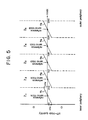
- the off-track quantity oftr shown in Figure 5 remains at each end of data areas Z1 to Z5 in case the gradient of the off-track quantity to the track varies due to temperature from the outer periphery of the magnetic disc 1 towards the inner periphery thereof. That is, in Figure 5 showing the typical data areas Z1 to Z5, a1 to a5 denote changes in the off-track quantities after correction by the use of reference servo tracks.
- the off-track quantity is substantially zero at the position of each reference servo track, it gradually increases towards the end of the data area, and the maximum off-track quantity oftr remains at each end of the data areas Z1 to Z5. There is no problem if the off-track quantity oftr is a permissible amount, but some further action is required when it is desired to eliminate such amount as well.
- the gradients of the off-track quantities to the tracks at individual temperatures are previously stored in the memory of the microprocessor 8, and the actual temperature in the apparatus is detected by the temperature sensor 20. Then the stored gradient of the off-track quantity relative to the detected temperature is read out and, after computation has been executed on the basis of such gradient of the off-track quantity to the relevant track, the off-track quantity obtained with regard to the reference servo track is corrected so that the off-track quantity can be reduced substantially to zero in any of the data tracks.
- Figure 6 shows typical gradients a50 and a5 of the off-track quantity to one track at 50°C and 5°C, wherein arrows a and b represent a change in the number of tracks and a change in the off-track quantity, respectively.
- the gradients a50 and a5 of the off-track quantity to the track are computed from the change in the number of tracks and that in the off-track quantity, and the information thus obtained is stored previously in the memory of the microprocessor 8. It is assumed here that if the materials of the magnetic disc 1, the arm 4, the optical sensor 5 and so on are determined, the gradient of each off-track quantity is determined uniquely by a temperature.
- the actual temperature in the apparatus is detected by the temperature sensor 20, and the temperature information is fed to the microprocessor 8 via the processor 21 and the A/D converter 21.
- the microprocessor 8 computes the off-track quantity in the target track from the gradient a50 of the off-track quantity to the data track at 50°C.
- the magnetic head 3 After the magnetic head 3 has been displaced to the target track, the magnetic head 3 is further shifted slightly to an extent dependent on the calculated off-track quantity OFT from the position set at the zero-cross point of the optical sensor 2, whereby a just-tracking state is achieved.
- the above embodiment uses four light sensitive elements for obtaining output signals of four phases from the optical sensor, it is possible to use only two light sensitive elements and to obtain the remaining two output signals from them via inverters.
- reference servo tracks may be formed on the individual magnetic discs as described above, or reference servo tracks may be formed merely on a single magnetic disc disposed at the centre and such tracks may be utilized for access to data tracks on the remaining upper and lower discs.
- the previously stored off-track quantity is corrected at the time of displacing the magnetic head to achieve a just-tracking state, it becomes possible to ensure high-precision tracking with the off-track quantity reduced substantially to zero in any data track, and also to eliminate the time that may otherwise be required until reading out a servo signal, thereby expediting the head displacement.
- data can be written along the entire length of each circular data track, as there is no servo pattern in the data track, so that the efficiency of utilizing the magnetic disc surface is enhanced.
- the respective off-track quantities in the data areas can be corrected individually by disposing four reference servo tracks corresponding to the four-phase output signals of the optical sensor, and further correction is possible with regard to periodicity variation in the periodic output signal of the position detecting means.
Landscapes
- Moving Of The Head To Find And Align With The Track (AREA)
Applications Claiming Priority (4)
| Application Number | Priority Date | Filing Date | Title |
|---|---|---|---|
| JP61201140A JPS6356885A (ja) | 1986-08-27 | 1986-08-27 | 磁気デイスク装置 |
| JP201140/86 | 1986-08-27 | ||
| JP205713/86 | 1986-09-01 | ||
| JP61205713A JPS6361477A (ja) | 1986-09-01 | 1986-09-01 | 磁気デイスク装置 |
Publications (3)
| Publication Number | Publication Date |
|---|---|
| EP0259039A2 true EP0259039A2 (fr) | 1988-03-09 |
| EP0259039A3 EP0259039A3 (en) | 1989-11-29 |
| EP0259039B1 EP0259039B1 (fr) | 1993-02-24 |
Family
ID=26512591
Family Applications (1)
| Application Number | Title | Priority Date | Filing Date |
|---|---|---|---|
| EP87307171A Expired - Lifetime EP0259039B1 (fr) | 1986-08-27 | 1987-08-13 | Appareil à disques magnétiques |
Country Status (5)
| Country | Link |
|---|---|
| US (1) | US4974109A (fr) |
| EP (1) | EP0259039B1 (fr) |
| CA (1) | CA1333938C (fr) |
| DE (1) | DE3784287T2 (fr) |
| MY (1) | MY100768A (fr) |
Cited By (6)
| Publication number | Priority date | Publication date | Assignee | Title |
|---|---|---|---|---|
| EP0450629A1 (fr) * | 1990-04-06 | 1991-10-09 | Sony Corporation | Dispositif d'enregistrement et de reproduction et milieu d'enregistrement pour cela |
| US5268801A (en) * | 1990-10-12 | 1993-12-07 | Servo Track Writer Corporation | Method and apparatus for effecting data transfer with high precision reference data on a rotatable storage media |
| US5319509A (en) * | 1990-10-12 | 1994-06-07 | Servo Track Writer Corporation | Method and apparatus for controlling and analyzing a data storage system |
| FR2699720A1 (fr) * | 1992-12-23 | 1994-06-24 | Raymond Engineering | Unité d'exploitation de disques magnétiques, notamment unité de mémoire. |
| EP0651377A1 (fr) * | 1993-10-27 | 1995-05-03 | Hewlett-Packard Company | Capteurs de position pour des lecteurs de disque d'ordinateur |
| EP0492774B1 (fr) * | 1990-12-21 | 1997-04-09 | Fujitsu Limited | Procédé et système pour la correction offset du signal de position de la tête |
Families Citing this family (19)
| Publication number | Priority date | Publication date | Assignee | Title |
|---|---|---|---|---|
| KR0144463B1 (ko) * | 1988-10-26 | 1998-07-15 | 오오가 노리오 | 자기 디스크 장치 |
| JP2785195B2 (ja) * | 1989-01-11 | 1998-08-13 | ソニー株式会社 | ディスク装置の光学式エンコーダ |
| US5187620A (en) * | 1989-01-31 | 1993-02-16 | Kabushiki Kaisha Toshiba | Head position determination control apparatus of data recording/reproducing apparatus in a data surface servo system |
| US5223994A (en) * | 1989-10-02 | 1993-06-29 | Behr Michael I | System using superimposed, orthogonal buried servo signals |
| US5132861A (en) * | 1989-10-02 | 1992-07-21 | Behr Michael I | Systems using superimposed, orthogonal buried servo signals |
| JPH03225679A (ja) * | 1990-01-31 | 1991-10-04 | Sony Corp | デイスクドライブ装置 |
| JP3024184B2 (ja) * | 1990-08-14 | 2000-03-21 | ソニー株式会社 | サーボ信号記録方法 |
| JPH04248113A (ja) * | 1991-01-09 | 1992-09-03 | Sony Corp | 記録再生装置及びその記録媒体 |
| US5666236A (en) * | 1995-08-22 | 1997-09-09 | Iomega Corporation | Velocity control for a disk drive actuator |
| US5771130A (en) * | 1996-04-15 | 1998-06-23 | Phase Metrics | Method and apparatus for non-contact servo writing |
| KR100233669B1 (ko) * | 1996-11-01 | 2000-01-15 | 윤종용 | 트랙 쉬프트량 보상을 위한 서보버스트 기록방법및 서보제어방법 |
| US5930067A (en) * | 1997-07-29 | 1999-07-27 | Mobile Storage Technology, Inc. | Multi-harmonic compensator for track following in disk drives |
| US6538835B1 (en) * | 1999-02-22 | 2003-03-25 | Seagate Technology Llc | Position signal distortion compensation during a disc drive seek |
| US6788489B1 (en) * | 2000-05-09 | 2004-09-07 | Hitachi Global Storage Technologies Netherlands B.V. | Employing off-track capability in data access operations in a direct access storage device |
| US7215504B1 (en) | 2005-10-19 | 2007-05-08 | Western Digital Technologies, Inc. | Disk drive using an optical sensor to detect a position of an actuator arm |
| US7495857B1 (en) | 2005-12-30 | 2009-02-24 | Western Digital Technologies, Inc. | Servo writing a disk drive by writing spiral tracks using a mechanical position sensor |
| US7619844B1 (en) | 2005-12-30 | 2009-11-17 | Western Digital Technologies, Inc. | Disk drive comprising a mechanical position sensor to prevent a runaway condition |
| US7365932B1 (en) * | 2005-12-30 | 2008-04-29 | Western Digital Technologies, Inc. | Disk drive comprising an optical sensor for vibration mode compensation |
| US7480116B1 (en) | 2006-01-20 | 2009-01-20 | Western Digital Technologies, Inc. | Disk drive employing coarse position feedback from mechanical position sensor to improve format efficiency |
Family Cites Families (23)
| Publication number | Priority date | Publication date | Assignee | Title |
|---|---|---|---|---|
| US3737883A (en) * | 1971-08-18 | 1973-06-05 | Information Storage Systems | Linear positioning apparatus for memory disc pack drive mechanisms |
| US3753254A (en) * | 1971-08-19 | 1973-08-14 | Information Storage Systems | Thermal expansion compensation for disc drive memory |
| US3775655A (en) * | 1972-09-15 | 1973-11-27 | Xerox Corp | Method and apparatus for transducer temperature compensation |
| US3812533A (en) * | 1972-12-22 | 1974-05-21 | Vermont Res Corp | Information storage unit transducer positioning system |
| JPS49117007A (fr) * | 1973-03-09 | 1974-11-08 | ||
| US3881184A (en) * | 1974-05-28 | 1975-04-29 | Ibm | Adaptive digital servo system |
| US3924268A (en) * | 1974-08-05 | 1975-12-02 | Ibm | High density track follower control system for magnetic disk file |
| US3994016A (en) * | 1975-03-31 | 1976-11-23 | Honeywell Information Systems, Inc. | Head positioning servo system for disk drives |
| GB1549439A (en) * | 1976-07-06 | 1979-08-08 | Data Recording Instr Co | Magnetic disc storage devices |
| GB1549440A (en) * | 1976-07-06 | 1979-08-08 | Data Recording Instr Co | Magnetic storage devices |
| US4056831A (en) * | 1976-09-01 | 1977-11-01 | Data General Corporation | Thermal compensation for disk pack systems |
| GB1516239A (en) * | 1976-12-09 | 1978-06-28 | Burroughs Corp | Positioning system and method particularly useful for magnetic disc drives |
| USRE32075E (en) * | 1980-09-24 | 1986-01-28 | Quantum Corporation | Data transducer position control system for rotating disk data storage equipment |
| US4814909A (en) * | 1980-09-24 | 1989-03-21 | Quantum Corporation | Data transducer position control system for rotating disk data storage equipment |
| US4396959A (en) * | 1980-09-24 | 1983-08-02 | Quantum Corporation | Data transducer position control system for rotating disk data storage equipment |
| US4660106A (en) * | 1980-09-24 | 1987-04-21 | Quantum Corporation | Data transducer position control system for rotating disk data storage equipment |
| US4419701A (en) * | 1981-09-21 | 1983-12-06 | Quantum Corporation | Data transducer position control system for rotating disk data storage equipment |
| JPS60191481A (ja) * | 1984-03-09 | 1985-09-28 | Mitsubishi Electric Corp | デイスク装置 |
| JPS61122977A (ja) * | 1984-11-19 | 1986-06-10 | Brother Ind Ltd | オフトラツク修正の可能な磁気デイスク装置 |
| JPS623473A (ja) * | 1985-06-28 | 1987-01-09 | Toshiba Corp | 磁気ヘツドの位置決め制御方式 |
| US4620244A (en) * | 1985-11-20 | 1986-10-28 | Seagate Technology | Compensation method to correct thermally induced off-track errors in disc drives |
| JPS62145570A (ja) * | 1985-12-19 | 1987-06-29 | Victor Co Of Japan Ltd | デイスクドライブ装置 |
| GB2191627B (en) * | 1986-06-04 | 1990-07-04 | Alps Electric Co Ltd | Information recording disk driving devices and a method of controlling the head positioning of such devices |
-
1987
- 1987-08-04 US US07/081,651 patent/US4974109A/en not_active Ceased
- 1987-08-13 EP EP87307171A patent/EP0259039B1/fr not_active Expired - Lifetime
- 1987-08-13 DE DE8787307171T patent/DE3784287T2/de not_active Expired - Fee Related
- 1987-08-14 MY MYPI87001344A patent/MY100768A/en unknown
- 1987-08-26 CA CA000545351A patent/CA1333938C/fr not_active Expired - Fee Related
Cited By (7)
| Publication number | Priority date | Publication date | Assignee | Title |
|---|---|---|---|---|
| EP0450629A1 (fr) * | 1990-04-06 | 1991-10-09 | Sony Corporation | Dispositif d'enregistrement et de reproduction et milieu d'enregistrement pour cela |
| US5488519A (en) * | 1990-04-06 | 1996-01-30 | Sony Corporation | Recording and reproducing device having conductive spindle |
| US5268801A (en) * | 1990-10-12 | 1993-12-07 | Servo Track Writer Corporation | Method and apparatus for effecting data transfer with high precision reference data on a rotatable storage media |
| US5319509A (en) * | 1990-10-12 | 1994-06-07 | Servo Track Writer Corporation | Method and apparatus for controlling and analyzing a data storage system |
| EP0492774B1 (fr) * | 1990-12-21 | 1997-04-09 | Fujitsu Limited | Procédé et système pour la correction offset du signal de position de la tête |
| FR2699720A1 (fr) * | 1992-12-23 | 1994-06-24 | Raymond Engineering | Unité d'exploitation de disques magnétiques, notamment unité de mémoire. |
| EP0651377A1 (fr) * | 1993-10-27 | 1995-05-03 | Hewlett-Packard Company | Capteurs de position pour des lecteurs de disque d'ordinateur |
Also Published As
| Publication number | Publication date |
|---|---|
| DE3784287T2 (de) | 1993-07-29 |
| US4974109A (en) | 1990-11-27 |
| CA1333938C (fr) | 1995-01-10 |
| EP0259039B1 (fr) | 1993-02-24 |
| EP0259039A3 (en) | 1989-11-29 |
| DE3784287D1 (de) | 1993-04-01 |
| MY100768A (en) | 1991-02-14 |
Similar Documents
| Publication | Publication Date | Title |
|---|---|---|
| EP0259039B1 (fr) | Appareil à disques magnétiques | |
| EP0670572B1 (fr) | Appareil à entraínement de disque avec servomécanisme d'alignement | |
| US4499511A (en) | System for detecting position of a read-write head in seek operation on a disk memory having data servo spectors | |
| US5196970A (en) | Magnetic disc apparatus | |
| US4524397A (en) | Head positioning system for a disc data store | |
| KR0178510B1 (ko) | 싱글 스테이지 탐색방법 및 렌즈어셈블리 제어회로 | |
| US5268803A (en) | Disc memory apparatus utilizing detection of high-accuracy address data in short servo sectors for high speed accessing | |
| US5659438A (en) | Head positioning control system using stored voice coil motor correction data | |
| US5768226A (en) | Information recording and/or reproducing method and apparatus in which seek of a recording and/or reproducing head is corrected on the basis of detected moving velocity | |
| USRE35302E (en) | Magnetic disc apparatus | |
| EP0372953B1 (fr) | Méthode et appareil pour la détection de la vitesse d'accès pour un tourne-disque | |
| KR920006123B1 (ko) | 자기 디스크 구동 장치 및 자기 헤드 위치 설정 방법 | |
| US5675560A (en) | Information recording/reproducing apparatus with function of seeking light beam to target position, and method therefor | |
| US5793555A (en) | Seek optimization for disk files with side-by-side head | |
| US4931888A (en) | Tracking servo control for disc drive | |
| US5471444A (en) | Seek circuit for optical disc | |
| US4827362A (en) | Magnetic disk device having compensation for dimensional change | |
| KR960005415B1 (ko) | 자기디스크장치 | |
| EP0250138B1 (fr) | Servosystème pour un entraînement de disque rigide | |
| JP2695486B2 (ja) | データ面サーボ制御方式のディスク装置 | |
| KR960012892B1 (ko) | 자기디스크장치의 데이타 헤드의 오프셋 측정회로 | |
| JPS6358683A (ja) | 磁気デイスク装置 | |
| JP2595941B2 (ja) | ヘッドのシーク位置決め方法 | |
| JPH02304777A (ja) | 磁気デイスク装置の制御装置 | |
| JPH0411369A (ja) | データ記録再生装置のヘッド位置決め制御装置 |
Legal Events
| Date | Code | Title | Description |
|---|---|---|---|
| PUAI | Public reference made under article 153(3) epc to a published international application that has entered the european phase |
Free format text: ORIGINAL CODE: 0009012 |
|
| AK | Designated contracting states |
Kind code of ref document: A2 Designated state(s): DE FR GB SE |
|
| PUAL | Search report despatched |
Free format text: ORIGINAL CODE: 0009013 |
|
| AK | Designated contracting states |
Kind code of ref document: A3 Designated state(s): DE FR GB SE |
|
| 17P | Request for examination filed |
Effective date: 19900324 |
|
| 17Q | First examination report despatched |
Effective date: 19910717 |
|
| GRAA | (expected) grant |
Free format text: ORIGINAL CODE: 0009210 |
|
| AK | Designated contracting states |
Kind code of ref document: B1 Designated state(s): DE FR GB SE |
|
| REF | Corresponds to: |
Ref document number: 3784287 Country of ref document: DE Date of ref document: 19930401 |
|
| ET | Fr: translation filed | ||
| PGFP | Annual fee paid to national office [announced via postgrant information from national office to epo] |
Ref country code: GB Payment date: 19930812 Year of fee payment: 7 |
|
| PGFP | Annual fee paid to national office [announced via postgrant information from national office to epo] |
Ref country code: SE Payment date: 19930817 Year of fee payment: 7 |
|
| PGFP | Annual fee paid to national office [announced via postgrant information from national office to epo] |
Ref country code: FR Payment date: 19930827 Year of fee payment: 7 |
|
| PGFP | Annual fee paid to national office [announced via postgrant information from national office to epo] |
Ref country code: DE Payment date: 19931029 Year of fee payment: 7 |
|
| PLBE | No opposition filed within time limit |
Free format text: ORIGINAL CODE: 0009261 |
|
| STAA | Information on the status of an ep patent application or granted ep patent |
Free format text: STATUS: NO OPPOSITION FILED WITHIN TIME LIMIT |
|
| 26N | No opposition filed | ||
| PG25 | Lapsed in a contracting state [announced via postgrant information from national office to epo] |
Ref country code: GB Effective date: 19940813 |
|
| PG25 | Lapsed in a contracting state [announced via postgrant information from national office to epo] |
Ref country code: SE Effective date: 19940814 |
|
| EAL | Se: european patent in force in sweden |
Ref document number: 87307171.6 |
|
| GBPC | Gb: european patent ceased through non-payment of renewal fee |
Effective date: 19940813 |
|
| PG25 | Lapsed in a contracting state [announced via postgrant information from national office to epo] |
Ref country code: FR Effective date: 19950428 |
|
| PG25 | Lapsed in a contracting state [announced via postgrant information from national office to epo] |
Ref country code: DE Effective date: 19950503 |
|
| EUG | Se: european patent has lapsed |
Ref document number: 87307171.6 |
|
| REG | Reference to a national code |
Ref country code: FR Ref legal event code: ST |