EP0259800A2 - Disjoncteur de protection de ligne bipolaire - Google Patents
Disjoncteur de protection de ligne bipolaire Download PDFInfo
- Publication number
- EP0259800A2 EP0259800A2 EP87112970A EP87112970A EP0259800A2 EP 0259800 A2 EP0259800 A2 EP 0259800A2 EP 87112970 A EP87112970 A EP 87112970A EP 87112970 A EP87112970 A EP 87112970A EP 0259800 A2 EP0259800 A2 EP 0259800A2
- Authority
- EP
- European Patent Office
- Prior art keywords
- bridge element
- circuit breaker
- pole circuit
- breaker according
- switching
- Prior art date
- Legal status (The legal status is an assumption and is not a legal conclusion. Google has not performed a legal analysis and makes no representation as to the accuracy of the status listed.)
- Granted
Links
- 230000007246 mechanism Effects 0.000 claims abstract description 21
- 239000000969 carrier Substances 0.000 claims description 5
- 239000011810 insulating material Substances 0.000 claims description 4
- 238000009434 installation Methods 0.000 claims description 3
- 238000000465 moulding Methods 0.000 claims description 3
- 238000001746 injection moulding Methods 0.000 claims description 2
- 238000003754 machining Methods 0.000 claims 1
- 238000005192 partition Methods 0.000 description 12
- 230000009471 action Effects 0.000 description 3
- 230000006872 improvement Effects 0.000 description 2
- 230000001960 triggered effect Effects 0.000 description 2
- 229920002430 Fibre-reinforced plastic Polymers 0.000 description 1
- 230000000712 assembly Effects 0.000 description 1
- 238000000429 assembly Methods 0.000 description 1
- 230000015572 biosynthetic process Effects 0.000 description 1
- 239000000919 ceramic Substances 0.000 description 1
- 150000001875 compounds Chemical class 0.000 description 1
- 239000004020 conductor Substances 0.000 description 1
- 238000010276 construction Methods 0.000 description 1
- 230000008878 coupling Effects 0.000 description 1
- 238000010168 coupling process Methods 0.000 description 1
- 238000005859 coupling reaction Methods 0.000 description 1
- 239000011151 fibre-reinforced plastic Substances 0.000 description 1
- 238000007731 hot pressing Methods 0.000 description 1
- 238000000034 method Methods 0.000 description 1
- 230000007935 neutral effect Effects 0.000 description 1
- 239000004033 plastic Substances 0.000 description 1
- 229920003023 plastic Polymers 0.000 description 1
- 230000008569 process Effects 0.000 description 1
- 238000000926 separation method Methods 0.000 description 1
- 239000000243 solution Substances 0.000 description 1
- 230000001360 synchronised effect Effects 0.000 description 1
Images
Classifications
-
- H—ELECTRICITY
- H01—ELECTRIC ELEMENTS
- H01H—ELECTRIC SWITCHES; RELAYS; SELECTORS; EMERGENCY PROTECTIVE DEVICES
- H01H71/00—Details of the protective switches or relays covered by groups H01H73/00 - H01H83/00
- H01H71/10—Operating or release mechanisms
- H01H71/1009—Interconnected mechanisms
-
- H—ELECTRICITY
- H01—ELECTRIC ELEMENTS
- H01H—ELECTRIC SWITCHES; RELAYS; SELECTORS; EMERGENCY PROTECTIVE DEVICES
- H01H71/00—Details of the protective switches or relays covered by groups H01H73/00 - H01H83/00
- H01H71/002—Details of the protective switches or relays covered by groups H01H73/00 - H01H83/00 with provision for switching the neutral conductor
-
- H—ELECTRICITY
- H01—ELECTRIC ELEMENTS
- H01H—ELECTRIC SWITCHES; RELAYS; SELECTORS; EMERGENCY PROTECTIVE DEVICES
- H01H71/00—Details of the protective switches or relays covered by groups H01H73/00 - H01H83/00
- H01H71/10—Operating or release mechanisms
- H01H71/1045—Multiple circuits-breaker, e.g. for the purpose of dividing current or potential drop
-
- H—ELECTRICITY
- H01—ELECTRIC ELEMENTS
- H01H—ELECTRIC SWITCHES; RELAYS; SELECTORS; EMERGENCY PROTECTIVE DEVICES
- H01H71/00—Details of the protective switches or relays covered by groups H01H73/00 - H01H83/00
- H01H71/10—Operating or release mechanisms
- H01H71/12—Automatic release mechanisms with or without manual release
- H01H71/24—Electromagnetic mechanisms
- H01H71/2409—Electromagnetic mechanisms combined with an electromagnetic current limiting mechanism
-
- H—ELECTRICITY
- H01—ELECTRIC ELEMENTS
- H01H—ELECTRIC SWITCHES; RELAYS; SELECTORS; EMERGENCY PROTECTIVE DEVICES
- H01H71/00—Details of the protective switches or relays covered by groups H01H73/00 - H01H83/00
- H01H71/10—Operating or release mechanisms
- H01H71/12—Automatic release mechanisms with or without manual release
- H01H71/24—Electromagnetic mechanisms
- H01H71/2463—Electromagnetic mechanisms with plunger type armatures
Definitions
- the invention relates to a two-pole circuit breaker in a shell design, with a multi-part housing with a magnetic release, with two switch poles, the switching planes of which are arranged next to one another and each of which is assigned a contact carrier, which are actuated together by a bridge element from the anchor of the magnetic release.
- Two-pole circuit breakers serve different purposes, such as. B. to secure single-phase cables with simultaneous separation of the neutral. Another possible application is to increase the breaking capacity by coupling the two contact break points, ie by double break. Space-saving two-pole circuit breakers are also often used for reasons of space, although two electrically separated conductor networks are switched simultaneously by mechanical actuation.
- a two-pole circuit breaker in shell design has become known from DE-OS 2 234 423, which describes an installation self-switch with a short-circuit and / or an overcurrent release, with a switching mechanism and two contact interruptions
- the switching mechanism is arranged centrally in this switch and is held on the housing shells by corresponding lugs, while the contact interruption points are arranged laterally in arc chambers located on both sides of the switching mechanism.
- This design makes it possible to use the switching mechanism that is customary for single-pole self-switches in a switch design with a simple interruption and to transmit the trigger movement from the trigger via a truss-like bridge element to the movable contact pieces.
- the object of the invention is therefore to provide a two-pole circuit breaker of the generic type, which is simple in construction and economical to produce and in which, while avoiding the disadvantages discussed above, the two switch poles are actuated with only one magnetic release, with the best possible use of space within the switch housing being realized should be.
- the bridge element is provided with a traverse which extends vertically through both switching planes and which acts directly on both contact carriers and is in mechanical engagement with both switching mechanisms and actuates the switching contacts directly when triggered.
- the magnetic release according to the invention is arranged off-center in one half of the housing, so that its striking armature is located in the switching plane of a switch pole and acts on the crossbar off-center.
- the switching level here and below means the continuation of the area spanned between the open contact pieces of one switch pole, which is parallel to that of the other switch pole.
- the bridge element executes a pivoting movement about an axis of rotation when it is acted upon by the impact anchor, said axis being arranged at a distance parallel to the cross member.
- the width of the guide surfaces is determined so that it corresponds at least to the length of the stroke of the impact anchor.
- the height of the guide surfaces ie the distance between the crossmember and the axis of rotation, is approximately twice the width of the guide surfaces, while the thickness of the guide part, ie the distance between the guide surfaces, corresponds approximately to half their width.
- the cross member is partially covered by the bridge element, the bridge element covering the distance between the switching devices, so that the cross member only emerges from the bridge element at the ends actuating the switching devices.
- the bridge element is preferably manufactured together with the guide surfaces and the integrally formed shaft journals as well as with the cross member as a one-piece molding made of insulating material.
- Plastic possibly also fiber-reinforced plastic, is considered as the insulating material, which is processed by injection molding. But it can also be provided that the bridge element made of other insulating materials, for. B. ceramic molding compounds, possibly with a supporting insert made of wire or the like.
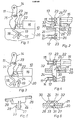
- FIG. 2 shows the top view of the arrangement shown in FIG. 1.
- parts of the switching mechanism 14 can be seen, which covers the switch pole 12 underneath and is separated from the neighboring switching mechanism 15 by the partition wall 20 and a second partition wall 21.
- Each of the partitions 20, 21 delimits a housing half, each with a switch pole 12, 13.
- the plane between the partitions 20, 21 is a parting plane by which the bridge element 24 used is divided into two sections of equal length.
- the switching mechanism 15 covers the switch pole 13 lying underneath.
- the bridge element 24 is transverse to the switching planes which are parallel to the housing partition walls 20, 21 arranged with a traverse 26.
- the magnetic release 16 is arranged, the impact armature 22 of which rests on the cross member 26 of the bridge element 24 and, in the event of tripping, acts on the bridge element on one side.
- guide surfaces 28 are formed on the bridge element 24, which are inserted and guided in a precisely fitting recess 30, which is formed between the partition walls 20, 21.
- An elongated hole is inserted in the contact carrier 11 as a guide 25 for the guide pin 23.
- the magnetic trigger 16 with its impact anchor 22 is constructed in a known manner, i. H. provided with a bobbin, a coil and a magnetic core, and shown only schematically.
- the dimensions of the recess 30 are precisely matched to those of the guide part 27 of the bridge element 24, so that the bridge element 24 can be inserted into the recess 30 with minimal play and the guide surfaces 28 lie tightly against one another.
- the guide part 27 provided with guide surfaces 28 is formed asymmetrically, ie on one half, onto the bridge element 24. This means that the correct installation position is clearly defined.
- the guide pin 23 slides in the guide 25 of the contact carrier 11 during its pivoting movement, which is effected by the action of the cross member 26 of the bridge element 24, which in turn is acted upon by the impact anchor 22 which has come out of the magnetic release 16.
- the cross member 26 also carries out a pivoting movement together with the bridge element 24 and assumes an opposite, ie to the left, inclined position when it is acted upon by the impact anchor 22 triggered.
- the magnetic release 15 is located in the switching plane, which is separated from the switch oil 12 visible in side view by the partition 20.
- FIG. 4 shows a corresponding top view of the arrangement in FIG. 3, as was shown in FIG. 2 for the arrangement from FIG. 1.
- the same parts are provided with the same reference numbers.
- the bridge element 24 has assumed a different position as a result of the action by the impact armature 22 of the magnetic release 16. While the formation 27 with the guide surfaces 28 can be seen on the left side of the bridge element 24 in FIG. 2, the guide part 27 can now be seen on the right side of the bridge element 24. As already explained in relation to FIG. 3, this is due to the fact that the bridge element has swiveled to the left, thereby revealing the view of the guide part 27 which can now be seen on the right-hand side when viewed from above.
- FIG. 5 shows a perspective view of a bridge element 24, which is formed from a cylindrical body, on which trusses 26 with a trapezoidal cross section are formed on both end faces.
- short shaft journals 33 are formed on the guide surfaces 28, the central axis of which is aligned with the axis of rotation or pivoting of the bridge element 24.
- FIG. 6 shows the partial bottom view of the guide part 27 of the bridge element 24 inserted into the recess 30 provided for this purpose in the area of the partition walls 20, 21.
- the shaft journals 33 integrally formed on the guide surfaces 28 of the guide part 27 engage clearly in recesses 31 provided for this purpose.
- the recesses 31 are recessed both into the partition 20 and into the bulge 32 of the partition 21 and in this way ensure the sufficient mobility of the bridge element 24 while maintaining the position required for the function.
Landscapes
- Breakers (AREA)
- Crystals, And After-Treatments Of Crystals (AREA)
Priority Applications (1)
| Application Number | Priority Date | Filing Date | Title |
|---|---|---|---|
| AT87112970T ATE72361T1 (de) | 1986-09-09 | 1987-09-04 | Zweipoliger leitungsschutzschalter. |
Applications Claiming Priority (2)
| Application Number | Priority Date | Filing Date | Title |
|---|---|---|---|
| DE19863630643 DE3630643A1 (de) | 1986-09-09 | 1986-09-09 | Zweipoliger leitungsschutzschalter |
| DE3630643 | 1986-09-09 |
Publications (3)
| Publication Number | Publication Date |
|---|---|
| EP0259800A2 true EP0259800A2 (fr) | 1988-03-16 |
| EP0259800A3 EP0259800A3 (en) | 1988-09-28 |
| EP0259800B1 EP0259800B1 (fr) | 1992-01-29 |
Family
ID=6309205
Family Applications (1)
| Application Number | Title | Priority Date | Filing Date |
|---|---|---|---|
| EP87112970A Expired - Lifetime EP0259800B1 (fr) | 1986-09-09 | 1987-09-04 | Disjoncteur de protection de ligne bipolaire |
Country Status (3)
| Country | Link |
|---|---|
| EP (1) | EP0259800B1 (fr) |
| AT (1) | ATE72361T1 (fr) |
| DE (2) | DE3630643A1 (fr) |
Families Citing this family (1)
| Publication number | Priority date | Publication date | Assignee | Title |
|---|---|---|---|---|
| US6930403B2 (en) | 2002-08-21 | 2005-08-16 | High Tide Associates, Inc. | Mobile electrical power source |
Family Cites Families (5)
| Publication number | Priority date | Publication date | Assignee | Title |
|---|---|---|---|---|
| US3193646A (en) * | 1962-05-02 | 1965-07-06 | Wadsworth Electric Mfg Co | Interlock for multi-pole circuit breakers |
| DE1286188B (de) * | 1965-09-09 | 1969-01-02 | Licentia Gmbh | Installationsselbstschalter mit Hilfskontakt |
| DE2048256A1 (de) * | 1970-10-01 | 1972-04-06 | Bbc Brown Boveri & Cie | Selbstschalter mit Nulleiterabschaltung |
| DE2234423A1 (de) * | 1972-07-13 | 1974-01-24 | Bbc Brown Boveri & Cie | Installationsselbstschalter in schalenbauweise |
| FR2563375B1 (fr) * | 1984-04-24 | 1988-05-20 | Legrand Sa | Disjoncteur a fonction differentielle |
-
1986
- 1986-09-09 DE DE19863630643 patent/DE3630643A1/de not_active Withdrawn
-
1987
- 1987-09-04 EP EP87112970A patent/EP0259800B1/fr not_active Expired - Lifetime
- 1987-09-04 AT AT87112970T patent/ATE72361T1/de not_active IP Right Cessation
- 1987-09-04 DE DE8787112970T patent/DE3776468D1/de not_active Expired - Lifetime
Also Published As
| Publication number | Publication date |
|---|---|
| EP0259800B1 (fr) | 1992-01-29 |
| ATE72361T1 (de) | 1992-02-15 |
| DE3630643A1 (de) | 1988-03-17 |
| DE3776468D1 (de) | 1992-03-12 |
| EP0259800A3 (en) | 1988-09-28 |
Similar Documents
| Publication | Publication Date | Title |
|---|---|---|
| EP1687835B1 (fr) | Commutateur | |
| EP0174904B1 (fr) | Dispositif de contact pour disjoncteur basse tension avec un levier de contact à deux bras | |
| DE69302599T2 (de) | Schaltstruktur für Lastschalter | |
| EP2061053A2 (fr) | Commutateur destiné à des applications à courant continu | |
| EP0309386B1 (fr) | Disjoncteur multipolaire de puissance à basse tension avec un boîtier isolant et chambre d'extinction d'arc | |
| DE9001448U1 (de) | Schaltvorrichtung mit geschützten Unterbrechern | |
| EP0039096A2 (fr) | Commutateur à piston de soufflage | |
| EP1073084B1 (fr) | Dispositif de contact de commutation pour disjoncteur | |
| EP0049209B1 (fr) | Commutateur de protection de construction compacte comprenant une broche de déclencheur | |
| DE4201255A1 (de) | Formgehaeuseschalter mit vielpoliger querstabanordnung | |
| EP0222684B1 (fr) | Montage de contacts pour interrupteur à charge à basse tension avec des contacts principaux et des contacts d'amorçage d'arc | |
| EP0180537A2 (fr) | Interrupteur du type MCCB à deux parts de boîte | |
| DE69309466T2 (de) | Doppelte Lichtbogenlaufschiene für die Lichtbogenleitkammer eines Schutzschalters | |
| EP0177438B1 (fr) | Interrupteur multipolaire avec des boîtiers séparés en matière isolante pour chaque pôle | |
| DE2548723C3 (de) | Mehrpoliger elektrischer Schalter schmaler Bauweise | |
| EP1135784A1 (fr) | Element de contact | |
| EP0000711A1 (fr) | Contacteur avec bornes de raccordement librement accessibles et disposées dans des plans différents | |
| DE2234423A1 (de) | Installationsselbstschalter in schalenbauweise | |
| EP0259800B1 (fr) | Disjoncteur de protection de ligne bipolaire | |
| DE2138381C3 (de) | Schutzschalter, insbesondere Leitungsschutzschalter | |
| DE3729741C2 (de) | Mehrpoliger Leistungsschalter | |
| EP0309384B1 (fr) | Dispositif interrupteur multipolaire basse tension avec un boîtier isolant sous-divisé en chambres parallèles | |
| EP0310885A2 (fr) | Contacteur électrique | |
| EP0432859B1 (fr) | Dispositif de contact apte à recevoir des contacts de coupure amovibles d'un appareil de commutation multipolaire | |
| DE1588270C (de) | Selbstschaltergehause |
Legal Events
| Date | Code | Title | Description |
|---|---|---|---|
| PUAI | Public reference made under article 153(3) epc to a published international application that has entered the european phase |
Free format text: ORIGINAL CODE: 0009012 |
|
| AK | Designated contracting states |
Kind code of ref document: A2 Designated state(s): AT BE CH DE FR GB IT LI |
|
| PUAL | Search report despatched |
Free format text: ORIGINAL CODE: 0009013 |
|
| AK | Designated contracting states |
Kind code of ref document: A3 Designated state(s): AT BE CH DE FR GB IT LI |
|
| RAP1 | Party data changed (applicant data changed or rights of an application transferred) |
Owner name: ASEA BROWN BOVERI AKTIENGESELLSCHAFT |
|
| 17P | Request for examination filed |
Effective date: 19881124 |
|
| 17Q | First examination report despatched |
Effective date: 19910510 |
|
| GRAA | (expected) grant |
Free format text: ORIGINAL CODE: 0009210 |
|
| AK | Designated contracting states |
Kind code of ref document: B1 Designated state(s): AT BE CH DE FR GB IT LI |
|
| REF | Corresponds to: |
Ref document number: 72361 Country of ref document: AT Date of ref document: 19920215 Kind code of ref document: T |
|
| ITF | It: translation for a ep patent filed | ||
| REF | Corresponds to: |
Ref document number: 3776468 Country of ref document: DE Date of ref document: 19920312 |
|
| GBT | Gb: translation of ep patent filed (gb section 77(6)(a)/1977) | ||
| ET | Fr: translation filed | ||
| PLBE | No opposition filed within time limit |
Free format text: ORIGINAL CODE: 0009261 |
|
| STAA | Information on the status of an ep patent application or granted ep patent |
Free format text: STATUS: NO OPPOSITION FILED WITHIN TIME LIMIT |
|
| 26N | No opposition filed | ||
| PGFP | Annual fee paid to national office [announced via postgrant information from national office to epo] |
Ref country code: FR Payment date: 19960813 Year of fee payment: 10 |
|
| PGFP | Annual fee paid to national office [announced via postgrant information from national office to epo] |
Ref country code: CH Payment date: 19960829 Year of fee payment: 10 |
|
| PGFP | Annual fee paid to national office [announced via postgrant information from national office to epo] |
Ref country code: BE Payment date: 19960904 Year of fee payment: 10 |
|
| PG25 | Lapsed in a contracting state [announced via postgrant information from national office to epo] |
Ref country code: LI Free format text: LAPSE BECAUSE OF NON-PAYMENT OF DUE FEES Effective date: 19970930 Ref country code: FR Free format text: THE PATENT HAS BEEN ANNULLED BY A DECISION OF A NATIONAL AUTHORITY Effective date: 19970930 Ref country code: CH Free format text: LAPSE BECAUSE OF NON-PAYMENT OF DUE FEES Effective date: 19970930 Ref country code: BE Free format text: LAPSE BECAUSE OF NON-PAYMENT OF DUE FEES Effective date: 19970930 |
|
| BERE | Be: lapsed |
Owner name: ASEA BROWN BOVERI A.G. Effective date: 19970930 |
|
| REG | Reference to a national code |
Ref country code: CH Ref legal event code: PL |
|
| REG | Reference to a national code |
Ref country code: FR Ref legal event code: ST |
|
| PGFP | Annual fee paid to national office [announced via postgrant information from national office to epo] |
Ref country code: AT Payment date: 20010824 Year of fee payment: 15 |
|
| PGFP | Annual fee paid to national office [announced via postgrant information from national office to epo] |
Ref country code: GB Payment date: 20010829 Year of fee payment: 15 |
|
| PGFP | Annual fee paid to national office [announced via postgrant information from national office to epo] |
Ref country code: DE Payment date: 20010919 Year of fee payment: 15 |
|
| REG | Reference to a national code |
Ref country code: GB Ref legal event code: IF02 |
|
| PG25 | Lapsed in a contracting state [announced via postgrant information from national office to epo] |
Ref country code: GB Free format text: LAPSE BECAUSE OF NON-PAYMENT OF DUE FEES Effective date: 20020904 Ref country code: AT Free format text: LAPSE BECAUSE OF NON-PAYMENT OF DUE FEES Effective date: 20020904 |
|
| PG25 | Lapsed in a contracting state [announced via postgrant information from national office to epo] |
Ref country code: DE Free format text: LAPSE BECAUSE OF NON-PAYMENT OF DUE FEES Effective date: 20030401 |
|
| GBPC | Gb: european patent ceased through non-payment of renewal fee |
Effective date: 20020904 |
|
| PG25 | Lapsed in a contracting state [announced via postgrant information from national office to epo] |
Ref country code: IT Free format text: LAPSE BECAUSE OF NON-PAYMENT OF DUE FEES;WARNING: LAPSES OF ITALIAN PATENTS WITH EFFECTIVE DATE BEFORE 2007 MAY HAVE OCCURRED AT ANY TIME BEFORE 2007. THE CORRECT EFFECTIVE DATE MAY BE DIFFERENT FROM THE ONE RECORDED. Effective date: 20050904 |