EP0259829A1 - Sortiermaschine - Google Patents
Sortiermaschine Download PDFInfo
- Publication number
- EP0259829A1 EP0259829A1 EP87113104A EP87113104A EP0259829A1 EP 0259829 A1 EP0259829 A1 EP 0259829A1 EP 87113104 A EP87113104 A EP 87113104A EP 87113104 A EP87113104 A EP 87113104A EP 0259829 A1 EP0259829 A1 EP 0259829A1
- Authority
- EP
- European Patent Office
- Prior art keywords
- tray
- sheets
- discharge
- trays
- entry
- Prior art date
- Legal status (The legal status is an assumption and is not a legal conclusion. Google has not performed a legal analysis and makes no representation as to the accuracy of the status listed.)
- Granted
Links
- 238000007599 discharging Methods 0.000 claims description 6
- 239000000463 material Substances 0.000 claims description 2
- 230000003287 optical effect Effects 0.000 claims description 2
- 230000005484 gravity Effects 0.000 abstract description 2
- 230000007246 mechanism Effects 0.000 description 8
- 230000005611 electricity Effects 0.000 description 5
- 238000001514 detection method Methods 0.000 description 4
- 239000002184 metal Substances 0.000 description 4
- 229910052751 metal Inorganic materials 0.000 description 4
- 230000003068 static effect Effects 0.000 description 4
- 230000000694 effects Effects 0.000 description 2
- 230000000717 retained effect Effects 0.000 description 2
- 230000007723 transport mechanism Effects 0.000 description 2
- RYGMFSIKBFXOCR-UHFFFAOYSA-N Copper Chemical compound [Cu] RYGMFSIKBFXOCR-UHFFFAOYSA-N 0.000 description 1
- 239000010953 base metal Substances 0.000 description 1
- 210000000078 claw Anatomy 0.000 description 1
- 238000010276 construction Methods 0.000 description 1
- 229910052802 copper Inorganic materials 0.000 description 1
- 239000010949 copper Substances 0.000 description 1
- 230000002093 peripheral effect Effects 0.000 description 1
- 238000012805 post-processing Methods 0.000 description 1
Images


Classifications
-
- G—PHYSICS
- G03—PHOTOGRAPHY; CINEMATOGRAPHY; ANALOGOUS TECHNIQUES USING WAVES OTHER THAN OPTICAL WAVES; ELECTROGRAPHY; HOLOGRAPHY
- G03G—ELECTROGRAPHY; ELECTROPHOTOGRAPHY; MAGNETOGRAPHY
- G03G15/00—Apparatus for electrographic processes using a charge pattern
- G03G15/65—Apparatus which relate to the handling of copy material
- G03G15/6538—Devices for collating sheet copy material, e.g. sorters, control, copies in staples form
-
- B—PERFORMING OPERATIONS; TRANSPORTING
- B65—CONVEYING; PACKING; STORING; HANDLING THIN OR FILAMENTARY MATERIAL
- B65H—HANDLING THIN OR FILAMENTARY MATERIAL, e.g. SHEETS, WEBS, CABLES
- B65H31/00—Pile receivers
- B65H31/24—Pile receivers multiple or compartmented, e.d. for alternate, programmed, or selective filling
-
- B—PERFORMING OPERATIONS; TRANSPORTING
- B65—CONVEYING; PACKING; STORING; HANDLING THIN OR FILAMENTARY MATERIAL
- B65H—HANDLING THIN OR FILAMENTARY MATERIAL, e.g. SHEETS, WEBS, CABLES
- B65H39/00—Associating, collating, or gathering articles or webs
- B65H39/10—Associating articles from a single source, to form, e.g. a writing-pad
- B65H39/11—Associating articles from a single source, to form, e.g. a writing-pad in superposed carriers
-
- B—PERFORMING OPERATIONS; TRANSPORTING
- B65—CONVEYING; PACKING; STORING; HANDLING THIN OR FILAMENTARY MATERIAL
- B65H—HANDLING THIN OR FILAMENTARY MATERIAL, e.g. SHEETS, WEBS, CABLES
- B65H2403/00—Power transmission; Driving means
- B65H2403/50—Driving mechanisms
- B65H2403/51—Cam mechanisms
- B65H2403/511—Cam mechanisms involving cylindrical cam, i.e. cylinder with helical groove at its periphery
-
- B—PERFORMING OPERATIONS; TRANSPORTING
- B65—CONVEYING; PACKING; STORING; HANDLING THIN OR FILAMENTARY MATERIAL
- B65H—HANDLING THIN OR FILAMENTARY MATERIAL, e.g. SHEETS, WEBS, CABLES
- B65H2405/00—Parts for holding the handled material
- B65H2405/10—Cassettes, holders, bins, decks, trays, supports or magazines for sheets stacked substantially horizontally
- B65H2405/11—Parts and details thereof
- B65H2405/111—Bottom
- B65H2405/1111—Bottom with several surface portions forming an angle relatively to each other
-
- B—PERFORMING OPERATIONS; TRANSPORTING
- B65—CONVEYING; PACKING; STORING; HANDLING THIN OR FILAMENTARY MATERIAL
- B65H—HANDLING THIN OR FILAMENTARY MATERIAL, e.g. SHEETS, WEBS, CABLES
- B65H2408/00—Specific machines
- B65H2408/10—Specific machines for handling sheet(s)
- B65H2408/11—Sorters or machines for sorting articles
- B65H2408/112—Sorters or machines for sorting articles with stationary location in space of the bins and in-feed member movable from bin to bin
Definitions
- the present invention relates to a sorting machine, particularly to a sorting machine which receives recorded sheets delivered from a host sheet supplying unit, such as a copier or a printer, turns the sheets upside down, and discharges them selectively to one of a plurality of trays arranged in a vertical array, thereby permitting their distribution and reception.
- a host sheet supplying unit such as a copier or a printer
- a conventional sorting machine of this type which is so composed that a plurality of trays are vertically fixedly stacked with intervals therebetween, and recorded sheets conveyed from a feed opening by a transport mechanism are discharged to a tray selected by a tray selecting means.
- various other types of apparatus are known, including ones so designed that by an integral vertical movement of vertically spaced trays a selected tray entry is aligned with a sheet discharge portion so as to discharge sheets onto the selected tray.
- a first aspect of the present invention comprises a plurality of trays each having a tray pin on each side of the tray's sheet entry end, horizontal transport means for transporting sheets horizontally, a first guide member which turns the horizontally transported sheets to a vertical direction, vertical transport means for transporting the turned sheets vertically, discharge means for discharging the sheets transported by the vertical transport means to one of the plurality of trays, a second guide member which guides the sheets transported by vertical transport means to the discharge means so as to face the sheets down in a horizontal direction, transfer means for transferring the discharge means and the second guide member, and hold means, which is retractile in the vertical transport direction of the sheets according to the transfer of the discharge means, for holding the sheets in position between the hold means and the vertical transport means.
- the sheets transported horizontally by the horizontal transport means are turned to a vertical direction by the first guide member.
- the second guide member guides the sheets transported by the vertical transport means to the discharge means while returning them to a horizontal direction so as to face downward.
- the sheets discharged by the discharge means are received in a face-down condition into the trays.
- the hold means operates in a rectractile manner according to the transfer of the discharge means by the transfer means so as to hold the sheets in position, so that their dropping by gravity or jamming can be prevented during vertical transport as well.
- the transfer means mentioned above comprises a tray entry forming means which forms an entry between the two adjacent trays for the sheets being discharged according to the transfer of the discharge means.
- the tray entry forming means forms an entry for the sheets according to the transfer of the discharge means, so that it becomes possible to space the other trays closer.
- a third aspect of the present invention further comprises a tiltable light-shutting member which is tilted down by the sheets being discharged by the discharge means, and an optical sensor which detects the discharge of the sheets into a tray by detecting the tilt-down of such light-shutting member.
- the third aspect of the present invention enables detection of the discharge of sheets since detection output of the sensor changes upon tilt-down discharged. Therefore, discharge of the sheets can be accurately detected even if they are transparent.
- a fourth aspect of the present invention comprises feed means for feeding sheets to the horizontal transport means from a feed opening, a non-sorting tray which receives sheets fed by the feed means in a non-sorting mode, and shift means for shifting the flow so as to discharge the sheets fed by the feed means into the non-sorting tray.
- the direction of transport is shifted during the non-sorting mode by the shift means so as to discharge the sheets into the non-sorting tray from the feed means, thus making it possible to receive the sheets in a face-up condition into the non-sorting tray. Therefore, an operator can receive the sheets into the sorting trays or the non-sorting tray with their face turned in a desired direction.
- Fig. 1 shows an embodiment of the present invention.
- the present sorting machine has an outer case 1 formed like a box and having an aperture 1B, as shown in Fig. 1, making it possible to remove sorted sheets from the side of a plurality of trays 2 which are disposed in a vertical stack and accessible through the aperture 1B.
- the sheets delivered in the arrow A direction from a host sheet supplying unit (not shown), such as a copier, are led during the sorting mode from a feed opening 3 directly to a horizontal transport portion 4, from which they are turned to a vertical, downward direction along a guide plate 5.
- the sheets are led to a tray discharge unit 7 by a vertical transport portion 6, and further turned to horizontal to be discharged into the trays 2.
- An overall set up is described in detail referring to Fig. 2.
- Fig. 2 shows an embodiment which includes a non-sorting tray 8.
- 9A and 9B are upper and lower guide plates to be used when discharging sheets into a non-sorting tray 8
- 10A and 10B are upper and lower guide plates which guide sheets during a sorting mode from the feed opening 3 to a horizontal transport path 4.
- a guide path 11 which constitutes the feed opening 2 is provided with an entry sensor 11A which consists of a photo-interrupter and its light path interceptor, that is a tiltable lever 11B to shut or open the light path.
- the entry sensor 11A upon detecting that sheets have been introduced to the guide path 11, causes feed rollers 12, a horizontal transport belt 13, and a vertical transport belt 14 to be driven simultanteously.
- Reference numeral 15 denotes a deflector plate
- reference numeral 16 a solenoid which shifts the deflector plate 15 to a different direction.
- the deflector plate 15 is shifted clockwise by the solenoid 16 from the illustrated condition for discharge of sheets through non-sorting discharge rollers 17 into the non-sorting tray 8, keeping them stacked there.
- the machine is so composed that during a non-sorting mode a drive system for the feed rollers 12 and the discharge rollers 17 are disengaged by means of a clutch mechanism (not shown) from a drive system for the horizontal transport belt 13 and the vertical transport belt 14, so that only the feed rollers 12 and the discharge rollers 17 are driven and power is saved.
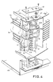
- a relationship of the vertical transport portion 6 to the discharge unit 7, which discharges sheets from the vertical transport portion 6 into trays 2 and to a tray entry forming member 20 which forms and secures an entry between the trays for sheet discharge is described with reference to Figs. 1 - 4.
- the two ends of a support frame 7A for the discharge unit 7, and a support frme 20A for the tray entry forming member 20, are fastened together as shown in Figs. 1 and 4. Accordingly, the dischrge unit 7 moves along with tray entry forming member 20 during vertical movement thereof. That is, in Fig. 2 a rotary drive shaft 21 rotates the tray entry forming member 20 while pivotally supporting the member 20 for free vertical movement.
- This rotary drive shaft 21 is driven for rotation by a drive motor 23 through a sprocket and chain mechanism 22.
- the support frame 20A of the tray entry forming member 20 is guided slidably upwardly and downwardly by a guide shaft 24 which is rigidly secured to a frame 47.
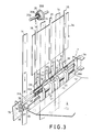
- Fig. 3 further describes the relationship between the vertical transport portion 6 and the discharge unit 7.
- discharge rollers 31 are mounted on a shaft 31A supported by the two ends of the support frame 7A of the discharge unit 7.
- Driven or pinch rollers 32 kept in contact with the discharge rollers 31 are likewise mounted on a shaft 32A supported by the two ends of the support frame 7A.
- Guide claw members 33 (hereinafter called deflector members) which deflect a sheet 34 so as to guide it into a tray 2 are disposed on both sides of the discharge rollers 31.
- a spiral spring 35 wound around a rotatable spool 35B rotatably mounted on a shaft 35A supported by a frame is in the form of a tape measure and functions such that no matter how far it is pulled out it will attempt to rewind with constant force around the rotatable spool 35B under its own spring force.
- a plurality of spiral springs 35 are provided on spools 35B around the shaft 35A. The end of each spiral spring 35 is fastened to the support frame 7A. The spiral springs 35 are pulled out with vertical downward movement of the discharge unit 7, and the sheet 34 is held in place between straight surfaces of the pulled out portions of the springs and surfaces of vertical transport belts 14 which have a frictional resistance.
- the sprial springs 35 are made of, for example, copper base metal material, and by coming into contact with the sheet 34 remove or discharge static electricity produced on the surface of the sheet 34. Furthermore, the spiral springs 35 are so formed that, when they are extended, their cross section as cut perpendicularly to the direction of extension becomes convex with respect to the side of sheet 34 with which they come into contact, and they beconme vertically linear, namely, in the direction of extension as if a metal tape measure was extended.
- Discharge rollers 31 are driven by a pulley 38, attached to a drive shaft 37, through drive gears 36 mounted respectively on discharge roller shaft 31A and drive shaft 37.
- Pulley 38 is driven by contact with one of the transport belts 14.
- Reference numeral 39 denotes metal fasteners which fasten spiral springs 35 to support frame 7A by screws 39A, respectively.
- the spiral springs 35 are retained along the curved outer faces of the metal fasteners 39, causing the ends of the springs to be fastened to the support frame 7a.
- the metal fasteners 39 and the support frame 7A are taken as separate parts, but they may be integrated into a single unit.
- a static electricity discharge brush 40 disposed to the support frame 7A, removes or discharges static electricity from the surface of a sheet being discharged.
- the tray entry forming member 20 provided at each side of trays 2, and mounted on a rotary shaft 21 so as to be slidable and to transmit torque, ad mentioned above, comprises a screw cam having a helical groove 20B along its column surface.
- Each individual tray 2 is provided with a tray pin 2A on each side of a sheet entry end of the tray, the tray pin 2A slidably engaging with a vertical guide groove 42 formed in the frame 47 in the vicinity of, and parallel to, the rotary shaft 21.
- a support casing 41 fastened to the frame 47, has a plurality of plungers 41A vertically disposed at equal intervals.
- five plungers 41A are provided on one support casing 41.
- the tip of each plunger 41A is somewhat rounded, this portion being located on the side of the guide groove 42 formed in the frame 47.
- the individual tray pins 2A, on both sides of the tray 2 are supported by the plungers 41A pressed by springs and protruding from the support casing 41, respectively.
- plungers 41A retract into the support casing 41 so that the pins 2A will be able to move. That is, rotation of screw cam 20 causes one tray pin 2A to be drawn into the helical groove 20B, so that the pin 2A can be moved upwardly or downwardly, thereby causing an axial force component of plunger 41A caused by the upward or downward movement to overcome the spring force of plunger 41A. It is desirable to make the number of plungers 41A per support casing 41, divided into the number of trays 2, a positive whole number.
- Each tray 2 is provided on its rear end (the end opposite to the sheet entry end) with a pair of rear end support tray pins 2B (hereinafter called rear end pins) which laterally extend from and are rigidly fixed, respectively, to opposite sides of the tray, as exemplified in Fig. 5.
- Each rear end pin 2B is slidably held in a slide groove 43A provided in a pin support frame 43.
- the slide grooves 43A are vertically spaced by an amount equal to the spacing of the trays 2.
- the slide grooves 43A have a steeper backward angle of inclination than do trays 2, as shown in Fig. 2.
- the pin support frame 43 is fastened to a support column 50 by screws 51. Furthermore, the support column 50 is secured to a base 49, as is guide shaft 24.
- An upper tray is raised by the screw cam 20 by means of the entry tray pin 2A, and a tray entry 44 is widely formed between the upper tray 2 above screw cam 20 and lower tray 2 below screw cam 20, whereupon the rear end of the upper tray 2 is somewhat moved up with the tray pin 2B being guided along the slide groove 43A.
- This operation facilitates discharging the sheets into the trays 2 without sticking or jamming even when a large stack of sheets is received n each tray 2.
- a second mechanism which is substantially identical to the one described above, comprising a second screw cam having a second helical groove, a second rotary drive shaft, a second support frame, a second guide shaft, a second set of support casings each having a plurality of plungers, and a second pin support frame, etc., is also disposed on the opposite side of the trays 2.
- reference numerals 45a and 45B denote a light-emitter and a light-receiver of a sheet discharge detecting sensor 45 provided on the side of the tray entry 44 of the discharge unit 7, and 45C denotes a light path.
- Discharge unit 7 is provided on its discharge side with a tiltable light-shutting plate 46. By this plate being tilted from an upright position, when the sheets are pinched between discharge rollers 31 and driven rollers 32 and discharged in succession almost horizontally, the right path 45C is intercepted to detect the fact that the sheets are being discharged. That is, provision of the shutting plate 46 permits detection even when the sheets are light-passing transparent film, etc.
- the sheet is guided by the horizontal transport belts 13 and the deflector guide plates 5 to a position between the vertical transport belts 14 and the spiral springs 35.
- the sheet while sliding along an extended straight surface of the springs 35, is held by the frictional force between the belts 14 and the springs 35, and is guided to the discharge unit 7.
- the sheet is deflected by the deflector members 33 and discharged onto a tray 2 by the discharge rollers 31 and the driven rollers 32. This discharge action is monitored by the sensor 45, while the sheet is cleared of electricity by the static electricity discharging brush 40 as shown in Fig. 3.
- the drive motor 23 rotates, through the sprocket and chain mechanism 22, the rotary shaft 21 on which the screw cam 20 is mounted.
- one revolution of the screw cam 20 in either direction lowers or raises the tray pin 2A held in contact with either the top or bottom of the screw cam 20, thus forming a next tray entry 44 on the tray one stage above or below to provide for the next discharge action.
- the vertical transport belts 14 are stretched on belt pulleys 14A and 14B pivotably mounted on shafts 14E and 14F supported by support units 14C and 14D both secured to an inner frame (not shown) of a case back cover 1A.
- the shaft 14E of the pulley 14A is supported by the body frame, composed in such a manner that the case back cover 1A can move rotatingly around shaft 14E. Therefore, should a jam occur near the discharge unit 7, the sheet which has jammed can be removed by opening the case back cover 1A with the shaft 14E as center.
- the present invention is equally applicable to a sorting machine composed in such a manner that individual trays are vertically disposed and fixed at specified intervals, a discharge unit is intermittently driven upwardly and downwardly by, for example, a combination mechanism of Geneva cam and Geneva wheel, and a recorded sheet is discharged onto a tray when the discharge unit has stopped.
Landscapes
- Engineering & Computer Science (AREA)
- Mechanical Engineering (AREA)
- Physics & Mathematics (AREA)
- General Physics & Mathematics (AREA)
- Pile Receivers (AREA)
Applications Claiming Priority (6)
| Application Number | Priority Date | Filing Date | Title |
|---|---|---|---|
| JP21067686A JPS6366068A (ja) | 1986-09-09 | 1986-09-09 | 丁合装置 |
| JP210675/86 | 1986-09-09 | ||
| JP137365/86U | 1986-09-09 | ||
| JP210676/86 | 1986-09-09 | ||
| JP13736586U JPS6342667U (de) | 1986-09-09 | 1986-09-09 | |
| JP21067586A JPS6366069A (ja) | 1986-09-09 | 1986-09-09 | 丁合装置 |
Publications (2)
| Publication Number | Publication Date |
|---|---|
| EP0259829A1 true EP0259829A1 (de) | 1988-03-16 |
| EP0259829B1 EP0259829B1 (de) | 1991-01-30 |
Family
ID=27317456
Family Applications (1)
| Application Number | Title | Priority Date | Filing Date |
|---|---|---|---|
| EP87113104A Expired EP0259829B1 (de) | 1986-09-09 | 1987-09-08 | Sortiermaschine |
Country Status (3)
| Country | Link |
|---|---|
| US (1) | US4842264A (de) |
| EP (1) | EP0259829B1 (de) |
| DE (1) | DE3767815D1 (de) |
Cited By (4)
| Publication number | Priority date | Publication date | Assignee | Title |
|---|---|---|---|---|
| EP0351356A3 (en) * | 1988-07-11 | 1990-08-01 | Daverio A.G. | Sorting apparatus |
| EP0357055A3 (de) * | 1988-09-01 | 1991-01-30 | Canon Kabushiki Kaisha | Bildaufzeichnungsgerät |
| DE4207765A1 (de) * | 1991-03-12 | 1992-09-17 | Ricoh Kk | Blatt-sortier- und -ablegeinrichtung |
| US6244594B1 (en) * | 1998-03-02 | 2001-06-12 | Tohoku Ricoh Co., Ltd. | Apparatus for storing sheets driven out of an image forming apparatus |
Families Citing this family (9)
| Publication number | Priority date | Publication date | Assignee | Title |
|---|---|---|---|---|
| GB2220197B (en) * | 1988-06-17 | 1993-01-20 | Mita Industrial Co Ltd | Sorter with noise suppression |
| US5048819A (en) * | 1990-01-15 | 1991-09-17 | Ikegami Tsushinki Co., Ltd. | Sorting machine having an uppermost tray which is only used in the non-sorting mode |
| DE4033237A1 (de) * | 1990-10-19 | 1992-04-23 | Helmut Steinhilber | Vorrichtung zum transportieren von bogen in bueromaschinen |
| US5180158A (en) * | 1992-01-21 | 1993-01-19 | Gradco (Japan) Ltd. | Moving bin-set sorter |
| US5263707A (en) * | 1992-03-09 | 1993-11-23 | Gradco (Japan) Ltd. | Combined stacker and sorter |
| US5257778A (en) * | 1993-03-08 | 1993-11-02 | Gradco (Japan) Ltd. | Sorter with molded tray shifting cam construction and method of making the cam |
| JP2801501B2 (ja) * | 1993-08-06 | 1998-09-21 | シャープ株式会社 | 用紙後処理装置 |
| JPH07232852A (ja) * | 1994-02-23 | 1995-09-05 | Minolta Co Ltd | ソーター |
| US9669428B2 (en) * | 2014-12-02 | 2017-06-06 | Pipp Mobile Storage Systems, Inc. | Product sorter |
Citations (3)
| Publication number | Priority date | Publication date | Assignee | Title |
|---|---|---|---|---|
| GB1248100A (en) * | 1968-07-29 | 1971-09-29 | Norfin | Improvements in collator devices |
| US4576371A (en) * | 1982-05-31 | 1986-03-18 | Fuji Xerox Co., Ltd. | Sorter having guide members |
| GB2168037A (en) * | 1984-12-06 | 1986-06-11 | Gradco Systems Inc | Sheet sorting apparatus |
Family Cites Families (16)
| Publication number | Priority date | Publication date | Assignee | Title |
|---|---|---|---|---|
| US3414254A (en) * | 1966-01-17 | 1968-12-03 | Norfin | Sheet collating device |
| US3372922A (en) * | 1966-09-29 | 1968-03-12 | Norfin | Sheet conveyor mechanism |
| US4361320A (en) * | 1978-12-21 | 1982-11-30 | Ricoh Company, Ltd. | Sheet distribution method and apparatus |
| GB2055086B (en) * | 1979-07-19 | 1983-04-07 | Ricoh Kk | Collating appparatus for copying machine |
| US4322069A (en) * | 1979-11-02 | 1982-03-30 | Konishiroku Photo Industry Co., Ltd. | Sheet sorting apparatus |
| JPS5678768A (en) * | 1979-11-27 | 1981-06-27 | Konishiroku Photo Ind Co Ltd | Sorter |
| US4405225A (en) * | 1980-12-23 | 1983-09-20 | Donald L. Snellman | Collator |
| US4548403A (en) * | 1981-11-18 | 1985-10-22 | Minolta Camera Kabushiki Kaisha | Sorter |
| JPS58183563A (ja) * | 1982-04-16 | 1983-10-26 | Toshiba Corp | 用紙の区分収納装置 |
| JPS58220054A (ja) * | 1982-06-12 | 1983-12-21 | Fuji Xerox Co Ltd | ソ−タの用紙案内装置 |
| JPS58220053A (ja) * | 1982-06-12 | 1983-12-21 | Fuji Xerox Co Ltd | ソ−タフイニツシヤ |
| US4561647A (en) * | 1984-02-13 | 1985-12-31 | Snellman Donald L | Sheet deflector and conveyor drive |
| US4580775A (en) * | 1984-03-02 | 1986-04-08 | Ikegani Tsushinki Company, Ltd. | Sheet sorting apparatus |
| JPH0669863B2 (ja) * | 1984-10-04 | 1994-09-07 | ミノルタカメラ株式会社 | ソ−タ |
| JPS61162464A (ja) * | 1985-01-07 | 1986-07-23 | Canon Inc | シ−ト積載装置 |
| JP3033925B2 (ja) * | 1992-09-02 | 2000-04-17 | サンデン株式会社 | 管路用液体センサ |
-
1987
- 1987-09-01 US US07/091,905 patent/US4842264A/en not_active Expired - Lifetime
- 1987-09-08 EP EP87113104A patent/EP0259829B1/de not_active Expired
- 1987-09-08 DE DE8787113104T patent/DE3767815D1/de not_active Expired - Lifetime
Patent Citations (3)
| Publication number | Priority date | Publication date | Assignee | Title |
|---|---|---|---|---|
| GB1248100A (en) * | 1968-07-29 | 1971-09-29 | Norfin | Improvements in collator devices |
| US4576371A (en) * | 1982-05-31 | 1986-03-18 | Fuji Xerox Co., Ltd. | Sorter having guide members |
| GB2168037A (en) * | 1984-12-06 | 1986-06-11 | Gradco Systems Inc | Sheet sorting apparatus |
Cited By (6)
| Publication number | Priority date | Publication date | Assignee | Title |
|---|---|---|---|---|
| EP0351356A3 (en) * | 1988-07-11 | 1990-08-01 | Daverio A.G. | Sorting apparatus |
| EP0357055A3 (de) * | 1988-09-01 | 1991-01-30 | Canon Kabushiki Kaisha | Bildaufzeichnungsgerät |
| US5154411A (en) * | 1988-09-01 | 1992-10-13 | Canon Kabushiki Kaisha | Image forming apparatus |
| DE4207765A1 (de) * | 1991-03-12 | 1992-09-17 | Ricoh Kk | Blatt-sortier- und -ablegeinrichtung |
| US5431390A (en) * | 1991-03-12 | 1995-07-11 | Ricoh Company, Ltd. | Sheet sorting and storing apparatus |
| US6244594B1 (en) * | 1998-03-02 | 2001-06-12 | Tohoku Ricoh Co., Ltd. | Apparatus for storing sheets driven out of an image forming apparatus |
Also Published As
| Publication number | Publication date |
|---|---|
| DE3767815D1 (de) | 1991-03-07 |
| US4842264A (en) | 1989-06-27 |
| EP0259829B1 (de) | 1991-01-30 |
Similar Documents
| Publication | Publication Date | Title |
|---|---|---|
| US4842264A (en) | Sorting machine | |
| US5020784A (en) | Method and apparatus for arranging papers | |
| US3618936A (en) | Jam detection system for sorting apparatus | |
| US4660820A (en) | Paper feeding apparatus for a copying machine/printer | |
| US3638937A (en) | Collator | |
| US4531344A (en) | Device for aligning and banding a pile of paper sheets | |
| US4433836A (en) | End of stack sensor | |
| US4819931A (en) | Sorting apparatus | |
| KR950001380Y1 (ko) | 소오터 | |
| US4548403A (en) | Sorter | |
| US4836529A (en) | Sorting machine | |
| US3484101A (en) | Sorting apparatus for documents | |
| JPH02147564A (ja) | 紙葉類排出装置及び画像形成装置 | |
| JP3714447B2 (ja) | 感光材料排出装置 | |
| US4148475A (en) | Sheet sorting device | |
| US5048819A (en) | Sorting machine having an uppermost tray which is only used in the non-sorting mode | |
| JPS59102761A (ja) | 用紙処理装置 | |
| CA1086342A (en) | Sheet feeding device | |
| US4830357A (en) | Sorting machine | |
| JPS6356139B2 (de) | ||
| JPH0616327A (ja) | ソータ | |
| JPH0750748Y2 (ja) | 写真感光材料処理機における搬送装置 | |
| JPS5846352B2 (ja) | 紙類の選別装置 | |
| JPH048341B2 (de) | ||
| JPH0520739Y2 (de) |
Legal Events
| Date | Code | Title | Description |
|---|---|---|---|
| PUAI | Public reference made under article 153(3) epc to a published international application that has entered the european phase |
Free format text: ORIGINAL CODE: 0009012 |
|
| AK | Designated contracting states |
Kind code of ref document: A1 Designated state(s): DE FR GB |
|
| RIN1 | Information on inventor provided before grant (corrected) |
Inventor name: SUZUKI, AKIHIRO Inventor name: KOSAKA, KENJI |
|
| 17P | Request for examination filed |
Effective date: 19880603 |
|
| 17Q | First examination report despatched |
Effective date: 19890929 |
|
| GRAA | (expected) grant |
Free format text: ORIGINAL CODE: 0009210 |
|
| AK | Designated contracting states |
Kind code of ref document: B1 Designated state(s): DE FR GB |
|
| REF | Corresponds to: |
Ref document number: 3767815 Country of ref document: DE Date of ref document: 19910307 |
|
| ET | Fr: translation filed | ||
| PLBE | No opposition filed within time limit |
Free format text: ORIGINAL CODE: 0009261 |
|
| STAA | Information on the status of an ep patent application or granted ep patent |
Free format text: STATUS: NO OPPOSITION FILED WITHIN TIME LIMIT |
|
| 26N | No opposition filed | ||
| PGFP | Annual fee paid to national office [announced via postgrant information from national office to epo] |
Ref country code: GB Payment date: 20000821 Year of fee payment: 14 |
|
| PGFP | Annual fee paid to national office [announced via postgrant information from national office to epo] |
Ref country code: FR Payment date: 20000918 Year of fee payment: 14 |
|
| PGFP | Annual fee paid to national office [announced via postgrant information from national office to epo] |
Ref country code: DE Payment date: 20001129 Year of fee payment: 14 |
|
| PG25 | Lapsed in a contracting state [announced via postgrant information from national office to epo] |
Ref country code: GB Free format text: LAPSE BECAUSE OF NON-PAYMENT OF DUE FEES Effective date: 20010908 |
|
| GBPC | Gb: european patent ceased through non-payment of renewal fee |
Effective date: 20010908 |
|
| PG25 | Lapsed in a contracting state [announced via postgrant information from national office to epo] |
Ref country code: DE Free format text: LAPSE BECAUSE OF NON-PAYMENT OF DUE FEES Effective date: 20020501 |
|
| PG25 | Lapsed in a contracting state [announced via postgrant information from national office to epo] |
Ref country code: FR Free format text: LAPSE BECAUSE OF NON-PAYMENT OF DUE FEES Effective date: 20020531 |
|
| REG | Reference to a national code |
Ref country code: FR Ref legal event code: ST |