EP0259981B2 - Procédé et appareil pour le traitement des images en couleurs - Google Patents
Procédé et appareil pour le traitement des images en couleurs Download PDFInfo
- Publication number
- EP0259981B2 EP0259981B2 EP87307143A EP87307143A EP0259981B2 EP 0259981 B2 EP0259981 B2 EP 0259981B2 EP 87307143 A EP87307143 A EP 87307143A EP 87307143 A EP87307143 A EP 87307143A EP 0259981 B2 EP0259981 B2 EP 0259981B2
- Authority
- EP
- European Patent Office
- Prior art keywords
- color
- color image
- image signal
- input
- image
- Prior art date
- Legal status (The legal status is an assumption and is not a legal conclusion. Google has not performed a legal analysis and makes no representation as to the accuracy of the status listed.)
- Expired - Lifetime
Links
- 238000003672 processing method Methods 0.000 title description 2
- 239000003086 colorant Substances 0.000 claims description 52
- 238000000034 method Methods 0.000 claims description 13
- 238000001514 detection method Methods 0.000 claims description 11
- 238000012545 processing Methods 0.000 claims description 5
- 238000012937 correction Methods 0.000 description 15
- 230000015654 memory Effects 0.000 description 6
- 238000010586 diagram Methods 0.000 description 5
- 239000000976 ink Substances 0.000 description 4
- 238000012546 transfer Methods 0.000 description 3
- 230000006835 compression Effects 0.000 description 2
- 238000007906 compression Methods 0.000 description 2
- PCHJSUWPFVWCPO-UHFFFAOYSA-N gold Chemical compound [Au] PCHJSUWPFVWCPO-UHFFFAOYSA-N 0.000 description 2
- 229910052737 gold Inorganic materials 0.000 description 2
- 239000010931 gold Substances 0.000 description 2
- 229910052709 silver Inorganic materials 0.000 description 2
- 239000004332 silver Substances 0.000 description 2
- 230000015572 biosynthetic process Effects 0.000 description 1
- 238000006243 chemical reaction Methods 0.000 description 1
- 238000013500 data storage Methods 0.000 description 1
- 238000013461 design Methods 0.000 description 1
- 230000000873 masking effect Effects 0.000 description 1
- 230000003287 optical effect Effects 0.000 description 1
- 238000006467 substitution reaction Methods 0.000 description 1
Images


Classifications
-
- H—ELECTRICITY
- H04—ELECTRIC COMMUNICATION TECHNIQUE
- H04N—PICTORIAL COMMUNICATION, e.g. TELEVISION
- H04N1/00—Scanning, transmission or reproduction of documents or the like, e.g. facsimile transmission; Details thereof
- H04N1/46—Colour picture communication systems
- H04N1/56—Processing of colour picture signals
- H04N1/60—Colour correction or control
- H04N1/62—Retouching, i.e. modification of isolated colours only or in isolated picture areas only
-
- Y—GENERAL TAGGING OF NEW TECHNOLOGICAL DEVELOPMENTS; GENERAL TAGGING OF CROSS-SECTIONAL TECHNOLOGIES SPANNING OVER SEVERAL SECTIONS OF THE IPC; TECHNICAL SUBJECTS COVERED BY FORMER USPC CROSS-REFERENCE ART COLLECTIONS [XRACs] AND DIGESTS
- Y10—TECHNICAL SUBJECTS COVERED BY FORMER USPC
- Y10S—TECHNICAL SUBJECTS COVERED BY FORMER USPC CROSS-REFERENCE ART COLLECTIONS [XRACs] AND DIGESTS
- Y10S347/00—Incremental printing of symbolic information
- Y10S347/90—Data processing for electrostatic recording
Definitions
- This invention relates to a color image processing method and apparatus which processes a color image signal to form a color image.
- a color image recording apparatus which records color image information using a recording method such as ink jet, heat transfer or eletrophotography.
- Fig. 2 is a block diagram for processing a signal in a color image recording apparatus of this type.
- An image reader or an image data storage not shown, outputs three color image signals 1a, 1b and 1c indicative of yellow, magenta and cyan, respectively, which are input to a color correction unit 2 which performs a color correction such as masking on these input signals.
- a gradation correction unit 3 performs a gradation correction on the corrected color signals from color correction unit 2.
- a printer 4 forms yellow, magenta and cyan images in accordance with the corrected gradation signals and records a color image.
- An apparatus of this type is most desired to reproduce a color faithful to that of an input image.
- it may be desired to output an image by changing a color of the input image.
- it may be desired to reproduce an original image in various colors.
- it is strongly desired to change only a particular color portion of the original image to another color to output the resulting image.
- U.S. Patent US-A-4,204,728 discloses an electronic color photography reproduction apparatus (color electrophotographic copying apparatus) which focuses an optical image passing through R-, G- and B- filters onto a photosensitive medium and develops the same using developers of cyan, magenta and yellow.
- color photography reproduction apparatus color electrophotographic copying apparatus
- Y, M, C color components contained in the partiarlar color
- Even in a color image recording apparatus which temporarily changes a color image into color component signals and records the colors, if colors not corresponding to three color (yellow, magenta and cyan) signals are printed with the yellow, magenta and cyan color signals, an image different in color from the input image can be produced.
- magenta, cyan and yellow are printed with yellow, magenta and cyan signals, respectively
- the red portion of yellow + magenta, the blue portion of magenta + cyan and the green portion of cyan + yellow will be reproduced with the blue of magenta + cyan + yellow will be reproduced with the blue of magenta + cyan, the green of cyan + yellow, and the red portion of yellow + magenta, respectively.
- all colors of the input image except for three monochromatic elements, yellow, magenta and cyan will be reproduced in different colors from those of the original image, so that it is impossible to replace only a particular color with another.
- U.S. Patent US-A-4,538,182 discloses a color reproduction apparatus which reproduces a plurality of particular colors, for example, two colors (red and black) or three colors (red, blue and black), in which the original red will be changed to black or the original black will be changed to red.
- a color reproduction apparatus which reproduces a plurality of particular colors, for example, two colors (red and black) or three colors (red, blue and black), in which the original red will be changed to black or the original black will be changed to red.
- red and black two colors
- red, blue and black red, blue and black
- European patent application EP-A-0205332 disdoses an arrangement for electronically modifying an electronic representation of an actual color image in order to, for example, correct imperfections in the color reproduction process. These imperfections arise, for example, because of the fact that the color filters which form part of the image reading apparatus and the colors used in the printing inks for reproducing the colored image do not match one another to a sufficient degree.
- This application discloses apparatus whose purpose is to apply color corrections as opposed to enabling an operator to substitute one color for another.
- European application EP-A-0188098 is also concerned with a video retouching system which is aimed at overcoming the same problem with which European application EP-A-0205332 is concerned.
- the present invention provides a method of processing a multi-color image, the method comprising the steps of:
- the present invention also provides apparatus for processing a multi-color image in which a first color of the multi-color image is replaced by a second color, the apparatus comprising:
- a switch SW1 selects a color in the input image to be replaced with another one among 24 colors herein.
- Terminals 8-1 to 8-24 are each given 12-bit data corresponding to a separate one of 24 colors so that the user can select a desired color freely among them.
- Each 12-bit data corresponding to a separate one of the 24 colors is determined in advance as follows.
- 12-bit signals are determined corresponding to respective colors and stored in a ROM, not shown, and applied to the corresponding terminals.
- a signal 9 selected by SW1 among such 12-bit signals is input to a coincidence detection unit 10 which also receives signals 7a - 7c after the division.
- Coincidence detection unit 10 includes an Exclusive-Or gate which compares 12 bits of signal 9 and 12 bits (4 x 3) of signals 7a - 7c on a bit-by-bit basis to output a signal 11 which will become high when all these compared bits coincide and will become low otherwise.
- Switch SW2 selects which color a particular color of the original image should be changed to. To this end, there are also 24 colors prepared herein. Terminals 12-1 to 12-24 are given different 4-bit data outputs, the number of bits of which is determined in accordance with the number of colors selectable.
- the signal 12 selected by SW2 is input as address data to ROMs 13a - 13c.
- Printer drive signals necessary for outputting the selected color are stored in the corresponding ROMs. For example, assume that a color be replaced and printed with green. In order to print this green, when three color signals to be input to the printer are (40, 20, 50) (assume that each color is one of 64 gradations 0-63.), the ROM outputs 14a - 14c obtained when green is selected by SW2 are set so that 14a, 14b and 14c are 40, 20, 50, respectively. In this way, three color drive signals corresponding to each color are stored in ROMs 13a - 13c.
- the respective ROM outputs 14a - 14c are input to selector 5 together with the respective outputs 15a - 15c of gradation correction unit 3.
- Selector 5 produces at its outputs 16a - 16c signals 15a - 15c when signal 11 is low and signals 14a - 14c when signal 11 is high.
- Selector outputs 16a - 16c are input to printer 4 which forms yellow, magenta and cyan images in accordance with these signals and records a color image.
- the user sets SW1 to orange and SW2 to green.
- signal 9 is 010101100010
- signal 12 is a 5-bit signal corresponding to green. If an input image is not orange, signals 7a - 7c will not coincide with signal 9, so that the output 11 of coincidence detection unit 10 becomes low. Therefore, selector 5 outputs, as outputs 16a - 16c, signals 15a - 15c processed in a normal manner which outputs are supplied to the printer to thereby perform printing.
- an Image can be output in which only orange of the input image is replaced with green.
- the color of an image portion to be replaced and a color to be printed therefor can be selected freely.
- the coincidence detection unit may be a ROM which receives signal 9 as the most significant address bits, signals 7a - 7c as the least significant address bits, stores 1 at addresses where the most and least significant bits are equal, 0 at addresses otherwise, and outputs the stored value as a signal 11.
- printer 4 can form a color image in accordance with signals 16a - 16c, it may be any of ink jet, heat transfer and electronic photography types.
- the printer While in the above arrangement the printer has been described as combining three colors yellow, magenta and cyan to form a color image, it may combine four or more colors which include black in addition to those three colors. Otherwise, it may be of the type which combines two colors such as red and black.
- output images with various colors in their backgrounds can be obtained from the original picture with no colored background. If black is included, output images can be obtained which have characters of various colors from the original picture with black characters.
- a picture can be output with no print in a portion corresponding to the original particular color portion and the no-print portion can be conveniently coated later with a color such as gold or silver which cannot be expressed by the printer. If black is induded, it will be convenient to reverse the negative and positive of a white and black image.
- predetermined color signals are output to the printer to output an image in which only any particular portion of the input image is replaced with any designated color.
- FIG. 4 An embodiment of this invention will now be described with reference to figure 4. It includes image input means for providing an image to be recorded, in a combination of color signals, replaced-color input means for providing in a combination of color signals, a designated replaced colorofthe image to be recorded, memory means for storing the combination of color signals supplied by the replaced color input means, comparison means for comparing the combination of color signals read out of the memory means and the combination of color signals supplied by the image input means to output a signal representing a coincidence when both the combinations coincide, output color designation means for designating an output color substituted for the replaced color in a combination of color signals, signal selection means for selectively outputting a color signal from the image input means or a color signal from the output color designation means in accordance with the output from the comparison means, and image output means for forming an image of plurality of colors in accordance with the output of the signal selection means.
- Colors of an original document to be replaced are read and stored in advance.
- signals indicative of the stored colors do not coincide with three color input image signals
- an input image signal subjected to regular color and gradation correction is output to the recording unit while when they coincide, the previously selected color signal is output to the recording unit. Therefore, an image in which only a particular color portion of the input image is replaced with another particular color can be output to a recording medium.
- Fig. 3 shows the basic structure of an arrangement which includes image input means a for providing an image to be recorded, in a combination of color signals, replaced-color input means b for providing, in a combination of color signals, a designated replaced color of the image to be recorded, memory means c for storing the combination of color signals supplied by the replaced-color input means, comparison means d for comparing the combination of color signals read out of the memory means c and the combination of color signals supplied by the image input means a to output a signal representing a coincidence when both the combinations coincide, output color designation means e for designating an output color substituted for the replaced color in a combination of color signals, signal selection means f for selectively outputting a color signal from the image input means a or a color signal from the output color designation means e in accordance with the output from the comparison means, and image output means such as a color printer g for forming an image of a plurality of colors in accordance with the output of the signal selection means f.
- image input means a for providing an image
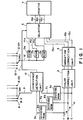
- Fig. 4 shows the circuit structure of the embodiment of the invention.
- like reference numeral denote like components.
- a read unit 105 reads a color image in an original document, a color film or the like, using an image sensor such as a CCD (charge coupled device) provided therein and outputs it as three color signals of Y. M.C. respectively, shown by 1a, 1b, 1c.
- Dividing ROMs (read only memories) 106a, 106b, 106c divides, by 16,6-bit color signals 1a, 1b, 1c, namely, converts same to corresponding 4-bit signals.
- ARAM random access memory
- Coincidence detection unit 110 compares the signals read from RAM 109 with the signals, as they are, supplied from dividing ROMs 106a - 106c to output a coincidence signal 116 when coincidence holds.
- An operation switch SW41 designetes a colorto be recorded among, for example, 24 colors, after color substitution.
- ROMs 113a, 113b, 113c output three corresponding combined color signals 114a - 114c corresponding to a designated color by switch SW41.
- the selection means including a selector 115 outputs to printer 4 the signals 114a, 114b, 114c from ROMs 113a, 113b, 113c when it receives a high or coincidence signal 116 from coincidence detection unit 110 and outputs signals 115a, 115b, 115c of gradation correction unit 3 when it receives no coincidence signal.
- a color designation mode (1) the user causes read unit 105 to read only a color portion to be replaced in an original document.
- Three 6-bit color (yellow, magenta and cyan) signals 1a - 1c representing the color components of the read color are divided by 16 at dividing ROMs 106a - 106c to be converted to 4-bit signals 7a - 7c.
- switches SW11, SW21, SW31 are connected to contacts 108a, 108b, 108c and a total of 12 data bits represented by signals 107a - 107c from ROMs 106a - 106c is stored in RAM 109.
- the user selects, by switch SW41, an output color to replace the original color. Namely, this switch SW41 selects that output color among 24 colors prepared in advance.
- Switch terminals 111-1 to 111-24 output different 4-bit data, the number of bits of which is determined in accordance with the number of colors to be selected.
- a 4-bit signal 112 selected by switch SW41 is input as address data to ROMs 113a, 113b, 113c which store printer drive signals necessary for outputting the selected color.
- the replaced color portion be printed with green.
- three color signals to be input to printer 4 are (40, 20, 50), each color being one of 64 gradations 0 - 63
- data is stored in advance in ROMs 113a, 113b, 113c so that the outputs 114a, 114b, 114c of ROMs 113a, 113b, 113c obtained when green is selected by SW41 are "40", "20", "50", respectively.
- Coincidence detection circuit 110 compares signals from RAM 109 and signals 107a - 107c from the document on a bit-by-bit basis, using its internal Exclusive-Or gate, not shown, which outputs to selector 115 a coincidence signal 116 which becomes high when all the compared bits coincide and low otherwise.
- Selector 115 outputs to printer 4 the signals 114a - 114c from ROMs 113a - 113c when signal 116 is high and outputs to printer 4 the signals 115a - 115c from gradation correction unit 3 when the coincidence signal 116 is low.
- color printer 4 which may be an ink jet printer, a heat transfer printer of an electronic photography printer to reproduce a full color image printed in yellow, magenta and cyan.
- dividing ROMs 106a - 106c which divide 6-bit signals by 16 and outputs 4-bit signals are used, only the most significant 4 bits of each of the 6-bit signals may be output. Alternatively, any means which can compress 6-bit signals to ones of bits fewer than 5 may be used.
- the coincidence detection unit 110 of Fig. 4 may include a ROM in which the signals from RAM 109 are input to the most significant address bits and the signals from original document are input to the least significant address bits, "1" is stored in advance to addresses where the most and least significant bits are equal, "0” is stored in advance in addresses where the most and least significant bits are not equal, and data "1” or "0” is output as a signal 116 to selector 115.
- printer 4 While in this embodiment the printer 4 has been described as combining three colors yellow, magenta and cyan to form a color image, it may combine four or more colors which include black in addition to those three colors. Otherwise, it may be of the type which combines two colors such as red and black.
- the kind of colors which can be selected in the color designation mode (2) is shown as 24 colors, it is not intended in a limitative sense and any kinds of colors may be prepared.
- white and black are included in these colors, the following advantages will be obtained. For example, if white is included in colors to be printed, a picture can be output with no print in a portion corresponding to the original particular color portion and the no-print portion can be conveniently coated later with a color such as gold or silver which cannot be expressed by the printer. If black is included, it will be convenient to reverse the negative and positive of a white and black image.
- a color portion to be replaced in the original document is read and stored in advance.
- the stored color signals do not coincide with three color input image signals
- the input image signals subjected to regular color and gradation corrections are output to the record unit while when they coincide, the color signals selected in advance are output to the record unit. Therefore, an image in which a particular color portion in the image is replaced with another designated color can be output to a recording medium.
Landscapes
- Engineering & Computer Science (AREA)
- Multimedia (AREA)
- Signal Processing (AREA)
- Color Image Communication Systems (AREA)
- Facsimile Image Signal Circuits (AREA)
- Dot-Matrix Printers And Others (AREA)
Claims (12)
- Procédé de traitement d'une image multicolore, le procédé comprenant les étapes suivantes :a) identification d'un point souhaité de l'image multicolore qui contient une première couleur destinée à être remplacée par une sélection manuelle dudit point souhaité ;b) lecture en machine dudit point souhaité de l'image multicolore pour obtenir un signal d'image en couleurs représentant ladite première couleur ;c) introduction du signal d'image en couleurs obtenu représentant ladite première couleur ;d) stockage du signal d'image en couleurs obtenu représentant ladite première couleur ;e) sélection d'un deuxième signal couleur représentant une deuxième couleur pour remplacer la première couleur ;f) lecture en machine de l'image multicolore pour obtenir un signal d'image en couleurs d'entrée ;g) comparaison dudit signal d'image en couleurs d'entrée avec le signal d'image en couleurs stocké représentant ladite première couleur ; eth) remplacement d'une partie quelconque du signal d'image en couleurs d'entrée par ledit deuxième signal couleur si ladite partie quelconque du signal d'image en couleurs d'entrée équivaut au signal d'image en couleurs stocké représentant ladite première couleur.
- Procédé selon la revendication 1, comportant l'étape de délivrance du signal d'image en couleurs formé par l'étape de remplacement et affichage de celui-ci en tant que deuxième image en couleurs.
- Procédé selon la revendication 1 ou 2, comportant l'étape de correction de la couleur du signal d'image en couleurs d'entrée.
- Procédé selon l'une quelconque des revendications 1 à 3, dans lequel le signal d'image en couleurs représentant ladite première couleur est divisé pour réduire le nombre de bits présents avant ledit stockage du signal.
- Procédé selon l'une quelconque des revendications précédentes, dans lequel le point souhaité de l'image en couleurs originale est identifié au moyen d'un numériseur.
- Procédé selon l'une quelconque des revendications précédentes, dans lequel la deuxième couleur est sélectionnée à partir de signaux stockés au préalable et représentatifs d'une pluralité de couleurs.
- Appareil pour le traitement d'une image multicolore dans lequel une première couleur de l'image multicolore est remplacée par une deuxième couleur, l'appareil comprenant :a) un moyen (105) de lecture en machine pour lire l'image multicolore ;b) un moyen de sélection manuelle pour identifier un point souhaité de l'image multicolore qui contient la première couleur à remplacer, ledit moyen (105) de lecture en machine étant sensible audit moyen de sélection manuelle pour lire ledit point souhaité dans l'image multicolore pour obtenir un signal d'image en couleurs représentant ladite première couleur ;c) un moyen (SW41) pour la sélection d'un deuxième signal couleur représentant ladite deuxième couleur ;d) un moyen (106 - 108) pour l'introduction du signal d'image en couleurs obtenu représentant ladite première couleur ;e) un moyen (109) pour le stockage du signal d'image en couleurs obtenu représentant ladite première couleur ;f) un moyen pour la commande dudit moyen (105) de lecture en machine après que le signal d'image en couleurs obtenu a été stocké pour lire l'image multicolore pour obtenir un signal d'image en couleurs d'entrée ;g) un moyen (110) pour la comparaison dudit signal d'image en couleurs d'entrée avec le signal d'image en couleurs stocké représentant ladite première couleur ; eth) un moyen (113 - 116) pour remplacer une partie quelconque du signal d'image en couleurs d'entrée par ledit deuxième signal couleur si ladite partie quelconque du signal d'image en couleurs d'entrée équivaut au signal d'image en couleurs stocké représentant ladite première couleur.
- Appareil selon la revendication 7, comportant un moyen (16, 4) pour la délivrance du signal d'image en couleurs formé par le moyen (113 - 116) de remplacement et pour l'affichage de celui-ci sous la forme d'une deuxième image en couleurs.
- Appareil selon la revendication 7 ou 8, comportant un moyen (2) pour la correction de la couleur du signal d'image en couleurs d'entrée.
- Appareil selon la revendication 7, 8 ou 9, comportant un moyen (106) pour la division du signal d'image en couleurs obtenu avant un stockage dans ledit moyen (109) de stockage pour réduire le nombre de bits présents.
- Appareil selon la revendication 10, comportant un moyen (SW11, SW21, SW31) pour la commutation de la sortie du moyen (106) de division entre une première position dans laquelle le signal divisé est appliqué audit moyen (109) de stockage et une deuxième position dans laquelle ledit signal divisé est appliqué au moyen de comparaison comprenant une unité (110) de détection de coïncidence.
- Appareil selon l'une quelconque des revendications 7 à 11, dans lequel le moyen de sélection comprend un moyen (SW41, 111 - 1 à 111 - 24) pour la sélection manuelle de l'un d'une pluralité de signaux représentatifs d'un nombre limité de deuxièmes couleurs.
Applications Claiming Priority (4)
| Application Number | Priority Date | Filing Date | Title |
|---|---|---|---|
| JP190034/86 | 1986-08-13 | ||
| JP61190034A JPH0734577B2 (ja) | 1986-08-13 | 1986-08-13 | カラー画像処理装置 |
| JP188772/86 | 1986-08-13 | ||
| JP61188772A JP2610020B2 (ja) | 1986-08-13 | 1986-08-13 | カラー画像処理装置 |
Publications (4)
| Publication Number | Publication Date |
|---|---|
| EP0259981A2 EP0259981A2 (fr) | 1988-03-16 |
| EP0259981A3 EP0259981A3 (en) | 1988-11-30 |
| EP0259981B1 EP0259981B1 (fr) | 1994-12-14 |
| EP0259981B2 true EP0259981B2 (fr) | 1999-05-06 |
Family
ID=26505139
Family Applications (1)
| Application Number | Title | Priority Date | Filing Date |
|---|---|---|---|
| EP87307143A Expired - Lifetime EP0259981B2 (fr) | 1986-08-13 | 1987-08-12 | Procédé et appareil pour le traitement des images en couleurs |
Country Status (3)
| Country | Link |
|---|---|
| US (2) | US4855765A (fr) |
| EP (1) | EP0259981B2 (fr) |
| DE (1) | DE3750860T3 (fr) |
Families Citing this family (33)
| Publication number | Priority date | Publication date | Assignee | Title |
|---|---|---|---|---|
| DE3856360T2 (de) * | 1987-05-15 | 2000-03-30 | Canon K.K., Tokio/Tokyo | Verfahren und Vorrichtung zur Farbbildverarbeitung |
| US5172223A (en) * | 1987-12-29 | 1992-12-15 | Canon Kabushiki Kaisha | Method of processing a color image to obtain color and black reproduction signals |
| JP3015033B2 (ja) * | 1988-07-20 | 2000-02-28 | キヤノン株式会社 | カラー画像処理方法 |
| JP2746939B2 (ja) * | 1988-09-26 | 1998-05-06 | 株式会社リコー | 色変換装置 |
| US5610639A (en) * | 1989-02-14 | 1997-03-11 | Canon Kabushiki Kaisha | Image forming apparatus with a correction recording condition feature and related method |
| JP2840323B2 (ja) * | 1989-09-28 | 1998-12-24 | キヤノン株式会社 | カラー画像記録装置 |
| US5105266A (en) * | 1989-11-30 | 1992-04-14 | Eastman Kodak Company | Single pass color substitution |
| EP0446019B1 (fr) * | 1990-03-06 | 1996-11-13 | Canon Kabushiki Kaisha | Appareil et procédé de traitement d'images |
| JP2985332B2 (ja) * | 1991-03-25 | 1999-11-29 | ソニー株式会社 | カラービデオ静止画像処理システム |
| US5202758A (en) * | 1991-09-16 | 1993-04-13 | Welch Allyn, Inc. | Fluorescent penetrant measurement borescope |
| US5251271A (en) * | 1991-10-21 | 1993-10-05 | R. R. Donnelley & Sons Co. | Method for automatic registration of digitized multi-plane images |
| US5841955A (en) * | 1991-12-02 | 1998-11-24 | Goss Graphic Systems, Inc. | Control system for a printing press |
| JP3210099B2 (ja) * | 1992-11-05 | 2001-09-17 | キヤノン株式会社 | 画像処理装置および画像処理方法 |
| US5432863A (en) * | 1993-07-19 | 1995-07-11 | Eastman Kodak Company | Automated detection and correction of eye color defects due to flash illumination |
| FR2710440B1 (fr) * | 1993-09-21 | 1995-10-20 | Le Falher Jean Richard | Dispositif empêchant l'affichage de certaines couleurs. |
| JPH07264392A (ja) * | 1994-02-04 | 1995-10-13 | Canon Inc | 画像編集装置、画像処理装置及び画像処理方法 |
| JP3554034B2 (ja) * | 1994-09-02 | 2004-08-11 | キヤノン株式会社 | カラー印刷装置及びその方法 |
| US5675716A (en) * | 1994-10-11 | 1997-10-07 | Seiko Epson Corporation | Method and apparatus for vivid color correction in binary printing devices |
| US5517335A (en) * | 1994-10-11 | 1996-05-14 | Seiko Epson Corporation | Apparatus and method for enhancing color saturation in halftoned images |
| EP0739127B1 (fr) * | 1995-04-21 | 2001-10-10 | Canon Kabushiki Kaisha | Procédé et appareil de traitement d'images |
| US5767980A (en) * | 1995-06-20 | 1998-06-16 | Goss Graphic Systems, Inc. | Video based color sensing device for a printing press control system |
| US5633734A (en) * | 1995-08-18 | 1997-05-27 | Eastman Kodak Company | Method and apparatus for modifying a fluorescent portion of a digital image |
| JP3679469B2 (ja) * | 1995-09-12 | 2005-08-03 | 富士写真フイルム株式会社 | 色修正方法 |
| US5805280A (en) * | 1995-09-28 | 1998-09-08 | Goss Graphic Systems, Inc. | Control system for a printing press |
| JPH09116737A (ja) * | 1995-10-16 | 1997-05-02 | Canon Inc | 画像処理装置及び方法 |
| JP3446015B2 (ja) * | 1996-03-29 | 2003-09-16 | カシオ電子工業株式会社 | カラープリンタ |
| EP1336934A3 (fr) * | 1997-08-29 | 2004-08-04 | Fuji Photo Film Co., Ltd. | Système pour le traitement d'images |
| JP3961734B2 (ja) * | 1999-12-24 | 2007-08-22 | 富士フイルム株式会社 | 画像処理方法、装置及び記録媒体 |
| US7319542B2 (en) * | 2002-10-29 | 2008-01-15 | Hewlett-Packard Development Company, L.P. | Document rehabilitation |
| JP4724413B2 (ja) * | 2004-11-26 | 2011-07-13 | キヤノン株式会社 | データ分類方法 |
| JP6048655B2 (ja) | 2012-12-11 | 2016-12-21 | セイコーエプソン株式会社 | 記録データ生成装置、記録システム、プログラム、記録データ生成方法及び画像データ表示方法 |
| JP7362312B2 (ja) | 2019-06-25 | 2023-10-17 | キヤノン株式会社 | 画像処理装置、撮像装置、画像処理装置の制御方法、及びプログラム |
| JP7731697B2 (ja) | 2021-05-25 | 2025-09-01 | キヤノン株式会社 | 画像処理装置、画像処理方法、撮像装置、およびプログラム |
Family Cites Families (6)
| Publication number | Priority date | Publication date | Assignee | Title |
|---|---|---|---|---|
| US4204728A (en) * | 1977-05-24 | 1980-05-27 | Canon Kabushiki Kaisha | Method and apparatus for color conversion |
| US4467348A (en) * | 1980-02-01 | 1984-08-21 | Canon Kabushiki Kaisha | Image recording device |
| US4538182A (en) * | 1981-05-11 | 1985-08-27 | Canon Kabushiki Kaisha | Image processing apparatus |
| DE3265413D1 (en) * | 1982-05-29 | 1985-09-19 | Hell Rudolf Dr Ing Gmbh | Method for tone-value-dependent colour removal in four color printing |
| GB8500493D0 (en) | 1985-01-09 | 1985-02-13 | Crosfield Electronics Ltd | Video retouching systems |
| GB8514608D0 (en) | 1985-06-10 | 1985-07-10 | Crosfield Electronics Ltd | Colour modification in image reproduction systems |
-
1987
- 1987-08-12 DE DE3750860T patent/DE3750860T3/de not_active Expired - Lifetime
- 1987-08-12 EP EP87307143A patent/EP0259981B2/fr not_active Expired - Lifetime
-
1988
- 1988-11-29 US US07/277,515 patent/US4855765A/en not_active Expired - Lifetime
-
1989
- 1989-07-13 US US07/379,177 patent/US5003326A/en not_active Expired - Lifetime
Also Published As
| Publication number | Publication date |
|---|---|
| DE3750860D1 (de) | 1995-01-26 |
| DE3750860T3 (de) | 1999-10-14 |
| US4855765A (en) | 1989-08-08 |
| EP0259981A2 (fr) | 1988-03-16 |
| EP0259981B1 (fr) | 1994-12-14 |
| DE3750860T2 (de) | 1995-05-04 |
| US5003326A (en) | 1991-03-26 |
| EP0259981A3 (en) | 1988-11-30 |
Similar Documents
| Publication | Publication Date | Title |
|---|---|---|
| EP0259981B1 (fr) | Procédé et appareil pour le traitement des images en couleurs | |
| US4727430A (en) | Halftone image recording method and apparatus therefor | |
| US4060829A (en) | Method of color correction | |
| US4959790A (en) | Apparatus and method for producing color corrected reproduction of colored original images | |
| CA1335080C (fr) | Methode et appareil de traitement d'images en couleurs | |
| EP0188098B1 (fr) | Systèmes de retouche vidéo | |
| US4931860A (en) | Image data composing system and process for storing both monochrome and polychrome image data | |
| US5225911A (en) | Means for combining data of different frequencies for a raster output device | |
| US5642439A (en) | Digital image processing method suitable for halftone representation based on dither process | |
| JPH0693747B2 (ja) | カラー画像再生システムを修正するための装置 | |
| JPH0371863A (ja) | 電子式グレースケールカラープリンタ用ページバッファシステム | |
| US5105267A (en) | Color conversion apparatus | |
| US4825296A (en) | Method of and apparatus for copying originals in which an image to be printed is evaluated by observing a corresponding low-resolution video image | |
| US20090207455A1 (en) | Image processing according to image output mode | |
| US4965664A (en) | Color image signal processing method and apparatus for recording a color image from input color image signals by converting an individual color signal component | |
| JPS59129853A (ja) | 色分解装置 | |
| US4803496A (en) | Method for recording a color image | |
| US5422740A (en) | Image forming apparatus which effects output gray level correction | |
| US5119184A (en) | Color image processing apparatus with digital color signal compression means | |
| JPH0513303B2 (fr) | ||
| US5077606A (en) | Color signal emphasizing/de-emphasizing circuit | |
| JP4083311B2 (ja) | 特色印刷用データ作成装置 | |
| GB2240897A (en) | Color correction and printing system for reproduction of computer-generated images | |
| US4862250A (en) | Still picture transmitting and receiving system | |
| US5451985A (en) | Area gradation control device and method for a thermal printer |
Legal Events
| Date | Code | Title | Description |
|---|---|---|---|
| PUAI | Public reference made under article 153(3) epc to a published international application that has entered the european phase |
Free format text: ORIGINAL CODE: 0009012 |
|
| AK | Designated contracting states |
Kind code of ref document: A2 Designated state(s): DE FR GB IT NL |
|
| PUAL | Search report despatched |
Free format text: ORIGINAL CODE: 0009013 |
|
| AK | Designated contracting states |
Kind code of ref document: A3 Designated state(s): DE FR GB IT NL |
|
| 17P | Request for examination filed |
Effective date: 19890419 |
|
| 17Q | First examination report despatched |
Effective date: 19900629 |
|
| GRAA | (expected) grant |
Free format text: ORIGINAL CODE: 0009210 |
|
| AK | Designated contracting states |
Kind code of ref document: B1 Designated state(s): DE FR GB IT NL |
|
| REF | Corresponds to: |
Ref document number: 3750860 Country of ref document: DE Date of ref document: 19950126 |
|
| ET | Fr: translation filed | ||
| ITF | It: translation for a ep patent filed | ||
| PLBI | Opposition filed |
Free format text: ORIGINAL CODE: 0009260 |
|
| 26 | Opposition filed |
Opponent name: OCE-NEDERLAND B.V. Effective date: 19950912 |
|
| NLR1 | Nl: opposition has been filed with the epo |
Opponent name: OCE-NEDERLAND B.V. |
|
| PLBF | Reply of patent proprietor to notice(s) of opposition |
Free format text: ORIGINAL CODE: EPIDOS OBSO |
|
| PLBF | Reply of patent proprietor to notice(s) of opposition |
Free format text: ORIGINAL CODE: EPIDOS OBSO |
|
| PLBF | Reply of patent proprietor to notice(s) of opposition |
Free format text: ORIGINAL CODE: EPIDOS OBSO |
|
| PLBF | Reply of patent proprietor to notice(s) of opposition |
Free format text: ORIGINAL CODE: EPIDOS OBSO |
|
| PLAW | Interlocutory decision in opposition |
Free format text: ORIGINAL CODE: EPIDOS IDOP |
|
| PLAW | Interlocutory decision in opposition |
Free format text: ORIGINAL CODE: EPIDOS IDOP |
|
| PUAH | Patent maintained in amended form |
Free format text: ORIGINAL CODE: 0009272 |
|
| STAA | Information on the status of an ep patent application or granted ep patent |
Free format text: STATUS: PATENT MAINTAINED AS AMENDED |
|
| 27A | Patent maintained in amended form |
Effective date: 19990506 |
|
| AK | Designated contracting states |
Kind code of ref document: B2 Designated state(s): DE FR GB IT NL |
|
| ET3 | Fr: translation filed ** decision concerning opposition | ||
| NLR2 | Nl: decision of opposition | ||
| REG | Reference to a national code |
Ref country code: GB Ref legal event code: IF02 |
|
| APAH | Appeal reference modified |
Free format text: ORIGINAL CODE: EPIDOSCREFNO |
|
| PGFP | Annual fee paid to national office [announced via postgrant information from national office to epo] |
Ref country code: NL Payment date: 20060815 Year of fee payment: 20 |
|
| PGFP | Annual fee paid to national office [announced via postgrant information from national office to epo] |
Ref country code: GB Payment date: 20060821 Year of fee payment: 20 |
|
| PGFP | Annual fee paid to national office [announced via postgrant information from national office to epo] |
Ref country code: FR Payment date: 20060825 Year of fee payment: 20 |
|
| PGFP | Annual fee paid to national office [announced via postgrant information from national office to epo] |
Ref country code: IT Payment date: 20060831 Year of fee payment: 20 |
|
| PGFP | Annual fee paid to national office [announced via postgrant information from national office to epo] |
Ref country code: DE Payment date: 20061018 Year of fee payment: 20 |
|
| REG | Reference to a national code |
Ref country code: GB Ref legal event code: PE20 |
|
| NLV7 | Nl: ceased due to reaching the maximum lifetime of a patent |
Effective date: 20070812 |
|
| PG25 | Lapsed in a contracting state [announced via postgrant information from national office to epo] |
Ref country code: GB Free format text: LAPSE BECAUSE OF EXPIRATION OF PROTECTION Effective date: 20070811 |
|
| PG25 | Lapsed in a contracting state [announced via postgrant information from national office to epo] |
Ref country code: NL Free format text: LAPSE BECAUSE OF EXPIRATION OF PROTECTION Effective date: 20070812 |