EP0260088A2 - Arbeitsdruckregeleinrichtung für Automatikgetriebe - Google Patents
Arbeitsdruckregeleinrichtung für Automatikgetriebe Download PDFInfo
- Publication number
- EP0260088A2 EP0260088A2 EP87307877A EP87307877A EP0260088A2 EP 0260088 A2 EP0260088 A2 EP 0260088A2 EP 87307877 A EP87307877 A EP 87307877A EP 87307877 A EP87307877 A EP 87307877A EP 0260088 A2 EP0260088 A2 EP 0260088A2
- Authority
- EP
- European Patent Office
- Prior art keywords
- line pressure
- solenoid
- control
- automatic transmission
- microcomputer
- Prior art date
- Legal status (The legal status is an assumption and is not a legal conclusion. Google has not performed a legal analysis and makes no representation as to the accuracy of the status listed.)
- Granted
Links
Images

Classifications
-
- F—MECHANICAL ENGINEERING; LIGHTING; HEATING; WEAPONS; BLASTING
- F02—COMBUSTION ENGINES; HOT-GAS OR COMBUSTION-PRODUCT ENGINE PLANTS
- F02N—STARTING OF COMBUSTION ENGINES; STARTING AIDS FOR SUCH ENGINES, NOT OTHERWISE PROVIDED FOR
- F02N19/00—Starting aids for combustion engines, not otherwise provided for
-
- B—PERFORMING OPERATIONS; TRANSPORTING
- B60—VEHICLES IN GENERAL
- B60W—CONJOINT CONTROL OF VEHICLE SUB-UNITS OF DIFFERENT TYPE OR DIFFERENT FUNCTION; CONTROL SYSTEMS SPECIALLY ADAPTED FOR HYBRID VEHICLES; ROAD VEHICLE DRIVE CONTROL SYSTEMS FOR PURPOSES NOT RELATED TO THE CONTROL OF A PARTICULAR SUB-UNIT
- B60W30/00—Purposes of road vehicle drive control systems not related to the control of a particular sub-unit, e.g. of systems using conjoint control of vehicle sub-units
- B60W30/18—Propelling the vehicle
- B60W30/192—Mitigating problems related to power-up or power-down of the driveline, e.g. start-up of a cold engine
- B60W30/194—Mitigating problems related to power-up or power-down of the driveline, e.g. start-up of a cold engine related to low temperature conditions, e.g. high viscosity of hydraulic fluid
-
- F—MECHANICAL ENGINEERING; LIGHTING; HEATING; WEAPONS; BLASTING
- F16—ENGINEERING ELEMENTS AND UNITS; GENERAL MEASURES FOR PRODUCING AND MAINTAINING EFFECTIVE FUNCTIONING OF MACHINES OR INSTALLATIONS; THERMAL INSULATION IN GENERAL
- F16H—GEARING
- F16H61/00—Control functions within control units of change-speed- or reversing-gearings for conveying rotary motion ; Control of exclusively fluid gearing, friction gearing, gearings with endless flexible members or other particular types of gearing
- F16H61/0021—Generation or control of line pressure
Definitions
- the present invention relates to a line pressure control system for an automatic transmission for a vehicle.
- Japanese Patent Application Laid-Open No. 57-101154 discloses a control system in which a line pressure control valve is provided for controlling line pressure of an automatic transmission by an output signal from a computer such that the line pressure is controlled in proportion to throttle valve opening degree and vehicle speed.
- the electronic control system is arranged such that if supply voltage from a battery drops because of increase of engine load and inactivation of the battery at cold engine, the microcomputer is reset. In the reset state, the line pressure is not controlled by the microcomputer.
- an electric circuit is provided to control the line pressure to a maximum value.
- the line pressure is high, pumping loss of an oil pump becomes large. The pumping loss affects starting of the engine. Therefore, it is preferable that the line pressure is low at cranking in order to prevent the pumping loss.
- the present invention seeks to provide a line pressure control system which may improve a starting characteristic of the engine at cranking.
- an electric circuit is provided to reduce the line pressure when a starting motor switch of an engine is closed for starting the engine.
- a line pressure control system for an automatic transmission for a motor vehicle, the vehicle having a microcomputer which operates to control line pressure in a hydraulic circuit for the automatic transmission, in accordance with driving conditions of the motor vehicle, the system comprising: a solenoid for controlling the line pressure; a control circuit responsive to an output signal of the microcomputer for energizing the solenoid to control the line pressure; a starting motor switch for operating a starting motor of an engine of the motor vehicle; a driving circuit electrically connected to the control circuit and to the starting motor switch, the driving circuit being arranged to respond to closing operation of the starting motor switch to operate the solenoid to reduce the line pressure.
- a line pressure control system for an automatic transmission for a motor vehicle having an engine, the system comprising: a microcomputer which operates to control line pressure in a hydraulic circuit for the automatic transmission, in accordance with driving conditions of the motor vehicle, a solenoid operated valve for controlling the line pressure; a control circuit responsive to an output signal of the microcomputer for energizing the solenoid to control the line pressure; a starter motor switch for operating a starter motor of the engine; and a driving circuit connected to the control circuit and to the starter motor switch, and arranged to respond to closing operation of the starter motor switch to operate the solenoid to reduce the line pressure.
- the output signal of the microcomputer is a pulse train duty ratio of which is controlled to control the energization of the solenoid
- the control circuit includes a transistor responsive to the pulses to intermittently energize the solenoid
- the driving circuit includes transistors responsive to the operation of the starter motor switch to operate the solenoid.
- automatic transmission 1 comprises a torque converter 2, an automatic transmission device 3, a final reduction gear 4 and a pressure oil control device 5 for pressure oil.
- the control device 5 is provided in a housing 5a.
- the torque converter 2 comprises an impeller 2a, a turbine 2b and a stator 2c.
- the impeller 2a is connected to a crank shaft 8 of an engine E through a drive plate 9 and a turbine shaft 10 secured to the turbine 2b is extended to the automatic transmission device 3.
- a cover 11 secured to the drive plate 9 is connected to an oil pump-driving shaft 12 which passes through the turbine shaft 10 and is coupled to an oil pump 13 provided in the rear portion of the automatic transmission means 3.
- the oil pump 13 is driven by the engine.
- the automatic transmission device 3 comprises a planetary gear device 15 and a plurality of fluid operated means for producing various operational ranges.
- the fluid operated means comprises a low and reverse brake 16, a forward clutch 17 and a reverse clutch 18.
- the turbine shaft 10 is connected to a forward sun gear 15a of the planetary gear 15 through the forward clutch 17 and is further connected to a reverse sun gear 15b through the reverse clutch 18.
- the clutches 17 and 18 By actuating the clutches 17 and 18 with line pressure, the power of the turbine shaft 10 is transmitted to the sun gear 15a or 15b.
- a short pinion 15c and a long pinion 15d are supported by a carrier 15e on which the low and reverse brake 16 is provided. Between the brake 16 and a center support 21, a one-way clutch 22 is provided. The carrier 15e may be locked by operation of the brake 16 and one-way clutch 22.
- the ring gear 15f of the planetary gear 15 is connected to an output shaft 23 mounted on the turbine shaft 10.
- the output shaft 23 is rotatably supported in the case 25 between a housing 7 of the torque converter 2 and the case 14 of the automatic transmission means 3.
- the final reduction gear 4 for the front wheel drive comprises a drive pinion 26 and a crown gear 29 of a differential 28.
- the drive pinion 26 is driven by the output shaft 23 through a reduction gear 27.
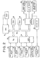
- a microcomputer has a central processor unit CPU 31, and A/D converter 33, an input interface 34, ROM 35, a RAM 36, an output interface 37, and a bus 32 connected between these elements.
- Output signals from a throttle position sensor 38 and an oil temperature sensor 39 are applied to the A/D converter 33.
- Output signals from a vehicle speed sensor 40, an engine speed sensor 41, and a driving range selection sensor 42 are applied to the input interface 34.
- the driving range selection sensor 42 produces output signals dependent on selected driving ranges such as D-range, R-range and neutral (N) range.
- Output signals of the output interface 37 are supplied to changing speed control solenoids 43, a torque converter lockup solenoid 44, and a line pressure control circuit 45.
- a driving circuit 46 for driving a line pressure control solenoid in the circuit 45 is provided to be supplied with an output signal of a starting motor switch 48.
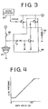
- the line pressure control circuit 45 comprises a PNP transistor Tr-1 and a line pressure control solenoid 50 connected to the transistor Tr-1 in series.
- the base of the transistor is connected to an output of the output interface 37.
- the driving circuit 46 comprises a PNP transistor Tr-2 connected to the transistor Tr-1 in parallel, an NPN transistor Tr-3 connected between the base of transistor Tr-2 and the ground.
- the base of the transistor Tr-3 is connected to the starting motor switch 48 through a diode D.
- an output pulse signal from the output interface 37 is supplied to the base of transistor Tr-1.
- the transistor When a higher voltage of the pulse signal is applied to the base of the transistor Tr-1, the transistor is turned off, and when the voltage becomes lower, the transistor is turned on to energize the line pressure control solenoid 50.
- the line pressure increases. In other words, the line pressure increases with increase of the duty ratio of the pulses applied to the base of transistor Tr-1.
- Fig. 4 shows the relationship between the line pressure and the duty ratio.
- the central processor unit 31 operates in accordance with input signals from sensors 38 to 42 and the output interface 37 produces output signals which are applied to solenoids 43 and 44.
- the solenoids 43 operate to control valves in the control means 5 to change the transmission ratio of the automatic transmission, and solenoid 44 operates to lock up the torque converter 2.
- the line pressure is controlled by the output signal of the output interface 37.
- the microcomputer If the voltage of the battery reduces to a predetermined value (for example 8 volt) by an abnormal condition such as cold engine operation, the microcomputer is reset. In the reset state, output interface 37 produces the output pulses at the duty ratio of 100%, which is fed to the base of transistor Tr-1. The base voltage of the transistor Tr-1 becomes a high level, so that the transistor Tr-1 is turned off. Thus, the current for driving the line pressure control solenoid 50 is cut off, so that the line pressure becomes a maximum value in order to provide a fail safe operation.
- a predetermined value for example 8 volt
- the switch 48 is closed, so that the voltage applied to a starting motor 47 is applied to the base of transistor Tr-3.
- the transistor Tr-3 is turned on, thereby turning on the transistor Tr-2. Accordingly, the current flows in the line pressure control solenoid 50 to energize it to decrease the line pressure to a minimum value.
- the present invention provides a line pressure control system which may exactly reduce the line pressure in cranking of the engine, thereby to prevent the pumping loss.
Landscapes
- Engineering & Computer Science (AREA)
- General Engineering & Computer Science (AREA)
- Mechanical Engineering (AREA)
- Automation & Control Theory (AREA)
- Transportation (AREA)
- Chemical & Material Sciences (AREA)
- Combustion & Propulsion (AREA)
- Control Of Transmission Device (AREA)
- Control Of Driving Devices And Active Controlling Of Vehicle (AREA)
Applications Claiming Priority (2)
| Application Number | Priority Date | Filing Date | Title |
|---|---|---|---|
| JP61213422A JPS6367448A (ja) | 1986-09-10 | 1986-09-10 | 自動変速機の油圧制御システム |
| JP213422/86 | 1986-09-10 |
Publications (3)
| Publication Number | Publication Date |
|---|---|
| EP0260088A2 true EP0260088A2 (de) | 1988-03-16 |
| EP0260088A3 EP0260088A3 (en) | 1988-10-12 |
| EP0260088B1 EP0260088B1 (de) | 1990-11-22 |
Family
ID=16638960
Family Applications (1)
| Application Number | Title | Priority Date | Filing Date |
|---|---|---|---|
| EP87307877A Expired - Lifetime EP0260088B1 (de) | 1986-09-10 | 1987-09-07 | Arbeitsdruckregeleinrichtung für Automatikgetriebe |
Country Status (5)
| Country | Link |
|---|---|
| US (1) | US4831896A (de) |
| EP (1) | EP0260088B1 (de) |
| JP (1) | JPS6367448A (de) |
| AU (1) | AU584519B2 (de) |
| DE (1) | DE3766328D1 (de) |
Cited By (3)
| Publication number | Priority date | Publication date | Assignee | Title |
|---|---|---|---|---|
| US5079971A (en) * | 1988-10-22 | 1992-01-14 | Mazda Motor Corporation | Line pressure control system for automatic transmission |
| US5213013A (en) * | 1988-10-22 | 1993-05-25 | Mazda Motor Corporation | Line pressure control system for automatic transmission |
| US6245783B1 (en) * | 1997-02-12 | 2001-06-12 | Gpi Nil Holdings, Inc. | Method of using neurotrophic sulfonamide compounds |
Families Citing this family (9)
| Publication number | Priority date | Publication date | Assignee | Title |
|---|---|---|---|---|
| JPH0716926Y2 (ja) * | 1988-12-23 | 1995-04-19 | マツダ株式会社 | 自動変速機のライン圧制御装置 |
| JPH0454366A (ja) * | 1990-06-22 | 1992-02-21 | Jatco Corp | 自動変速機の制御装置 |
| US5159856A (en) * | 1990-09-28 | 1992-11-03 | Mazda Motor Corporation | Automatic transmission line pressure control system |
| US5437204A (en) * | 1993-12-20 | 1995-08-01 | Ford Motor Company | System for selecting the operating ranges of an automatic transmission |
| US5433124A (en) * | 1993-12-20 | 1995-07-18 | Ford Motor Company | Electronic range selection in an automatic transmission |
| DE19504650C1 (de) * | 1995-02-13 | 1996-04-04 | Daimler Benz Ag | Einrichtung zur Getriebetemperaturerfassung |
| JP3548350B2 (ja) * | 1996-09-19 | 2004-07-28 | ジヤトコ株式会社 | 自動変速機制御装置 |
| KR100507485B1 (ko) * | 2003-05-27 | 2005-08-17 | 현대자동차주식회사 | 자동 변속기의 솔레노이드 플런저 보정 제어장치 및 방법 |
| EP2677210B1 (de) * | 2012-06-19 | 2016-04-20 | Turner Powertrain Systems Limited | Getriebehydraulikkreislauf |
Family Cites Families (12)
| Publication number | Priority date | Publication date | Assignee | Title |
|---|---|---|---|---|
| DE1917291A1 (de) * | 1969-04-03 | 1970-10-15 | Daimler Benz Ag | Druckregelvorrichtung fuer hydraulisch geschaltete automatische Getriebe,insbesondere fuer Kraftfahrzeuge |
| US3574288A (en) * | 1969-10-02 | 1971-04-13 | Gen Motors Corp | Transmission disabling apparatus |
| US4283970A (en) * | 1979-07-02 | 1981-08-18 | General Motors Corporation | Automatic transmission line pressure control |
| JPS5715019A (en) * | 1980-06-27 | 1982-01-26 | Fuji Heavy Ind Ltd | Changeover device for 2, 4 wheel drive in 4-wheel drive vehicle |
| JPS57101154A (en) * | 1980-12-15 | 1982-06-23 | Mitsubishi Motors Corp | Hydraulic control unit for automatic transmission |
| JPS588434A (ja) * | 1981-07-07 | 1983-01-18 | Fuji Heavy Ind Ltd | 4輪駆動車の切換制御装置 |
| JPS5877960A (ja) * | 1981-10-30 | 1983-05-11 | Mitsubishi Motors Corp | 自動変速機の油圧制御装置 |
| JPS5899546A (ja) * | 1981-12-04 | 1983-06-13 | Fuji Heavy Ind Ltd | 電磁式クラッチ付無段変速機の制御装置 |
| AU8954482A (en) * | 1982-08-04 | 1984-02-23 | Ford Motor Co. | Solenoid operated pressure regulation |
| DE3319428A1 (de) * | 1983-05-28 | 1984-11-29 | Agfa-Gevaert Ag, 5090 Leverkusen | Fotografisches aufzeichnungsmaterial mit einer vorlaeuferverbindung einer fotografisch wirksamen verbindung |
| CA1241214A (en) * | 1984-10-30 | 1988-08-30 | Shinya Nakamura | Control system and method for controllable output type hydraulic fluid pump of automatic transmission providing decreased pump output in association with the engine starting condition |
| US4779489A (en) * | 1986-06-27 | 1988-10-25 | Borg-Warner Automotive, Inc. | Control system for controlling transmission fluid pressure |
-
1986
- 1986-09-10 JP JP61213422A patent/JPS6367448A/ja active Pending
-
1987
- 1987-08-28 US US07/090,614 patent/US4831896A/en not_active Expired - Fee Related
- 1987-09-04 AU AU77976/87A patent/AU584519B2/en not_active Ceased
- 1987-09-07 EP EP87307877A patent/EP0260088B1/de not_active Expired - Lifetime
- 1987-09-07 DE DE8787307877T patent/DE3766328D1/de not_active Expired - Lifetime
Cited By (3)
| Publication number | Priority date | Publication date | Assignee | Title |
|---|---|---|---|---|
| US5079971A (en) * | 1988-10-22 | 1992-01-14 | Mazda Motor Corporation | Line pressure control system for automatic transmission |
| US5213013A (en) * | 1988-10-22 | 1993-05-25 | Mazda Motor Corporation | Line pressure control system for automatic transmission |
| US6245783B1 (en) * | 1997-02-12 | 2001-06-12 | Gpi Nil Holdings, Inc. | Method of using neurotrophic sulfonamide compounds |
Also Published As
| Publication number | Publication date |
|---|---|
| AU7797687A (en) | 1988-03-17 |
| JPS6367448A (ja) | 1988-03-26 |
| US4831896A (en) | 1989-05-23 |
| AU584519B2 (en) | 1989-05-25 |
| DE3766328D1 (de) | 1991-01-03 |
| EP0260088A3 (en) | 1988-10-12 |
| EP0260088B1 (de) | 1990-11-22 |
Similar Documents
| Publication | Publication Date | Title |
|---|---|---|
| US4831896A (en) | Line pressure control system for an automatic transmission | |
| US3938409A (en) | Control system for automatic transmissions of automotive vehicles | |
| US6647326B2 (en) | Driving control device of vehicle | |
| EP0716947B1 (de) | Hybridantriebs-Getriebe | |
| EP0037050A2 (de) | Überbrückungssteueranlage für ein mit einem überbrückbaren Drehmomentwandler ausgestattetes Wechselgetriebe | |
| US8012062B2 (en) | Apparatus and method of engine torque control during power take-off operation in a motor vehicle | |
| US4693081A (en) | Control system and method for controlling output type hydraulic fluid pump of automatic transmission providing increased pump output pressure with increase in engine load | |
| US5115694A (en) | Line pressure control at cranking and subsequent warming-up operation of engine | |
| EP0489200A1 (de) | Drucksteuervorrichtung für ein automatisches Kraftfahrzeuggetriebe | |
| JP2003172444A (ja) | 車両の駆動制御装置 | |
| US5557930A (en) | Drive unit having an electric motor | |
| JP2912009B2 (ja) | 変速機の制御装置 | |
| EP0415980B1 (de) | Elektronische regelvorrichtung für ein automatisches getriebe | |
| JPS61287835A (ja) | 無段変速機の制御装置 | |
| US4776239A (en) | Semiautomatic transmission | |
| EP0135790A2 (de) | Steuervorrichtung für den Antrieb von Zusatzaggregaten | |
| JPH0689843B2 (ja) | 自動変速機のトルクコンバータ出力軸回転数検出方法 | |
| US4982624A (en) | Hydraulic control device for automatic transmission for vehicle having friction engaging means operative in two jumping apart speed stages | |
| JPH0658405A (ja) | 自動変速機の制御装置 | |
| US4779492A (en) | Twin type hydraulic pressure control device with individual line pressure regulation valves for two stage automatic transmission | |
| JP2699592B2 (ja) | 自動変速機のライン圧制御装置 | |
| JP2958958B2 (ja) | 電子制御自動変速装置 | |
| WO1991005184A1 (en) | An overdrive gearset for a hydrokinetic transmission | |
| KR100290390B1 (ko) | 자동차용무단변속장치 | |
| KR100270041B1 (ko) | 자동변속차량의 아이들 스피드 컨트롤 방법 |
Legal Events
| Date | Code | Title | Description |
|---|---|---|---|
| PUAI | Public reference made under article 153(3) epc to a published international application that has entered the european phase |
Free format text: ORIGINAL CODE: 0009012 |
|
| 17P | Request for examination filed |
Effective date: 19870925 |
|
| AK | Designated contracting states |
Kind code of ref document: A2 Designated state(s): CH DE GB LI SE |
|
| PUAL | Search report despatched |
Free format text: ORIGINAL CODE: 0009013 |
|
| AK | Designated contracting states |
Kind code of ref document: A3 Designated state(s): CH DE GB LI SE |
|
| 17Q | First examination report despatched |
Effective date: 19890714 |
|
| GRAA | (expected) grant |
Free format text: ORIGINAL CODE: 0009210 |
|
| AK | Designated contracting states |
Kind code of ref document: B1 Designated state(s): CH DE GB LI SE |
|
| REF | Corresponds to: |
Ref document number: 3766328 Country of ref document: DE Date of ref document: 19910103 |
|
| PG25 | Lapsed in a contracting state [announced via postgrant information from national office to epo] |
Ref country code: GB Effective date: 19910907 |
|
| PG25 | Lapsed in a contracting state [announced via postgrant information from national office to epo] |
Ref country code: SE Effective date: 19910908 |
|
| PLBE | No opposition filed within time limit |
Free format text: ORIGINAL CODE: 0009261 |
|
| STAA | Information on the status of an ep patent application or granted ep patent |
Free format text: STATUS: NO OPPOSITION FILED WITHIN TIME LIMIT |
|
| PG25 | Lapsed in a contracting state [announced via postgrant information from national office to epo] |
Ref country code: LI Effective date: 19910930 Ref country code: CH Effective date: 19910930 |
|
| 26N | No opposition filed | ||
| GBPC | Gb: european patent ceased through non-payment of renewal fee | ||
| REG | Reference to a national code |
Ref country code: CH Ref legal event code: PL |
|
| PG25 | Lapsed in a contracting state [announced via postgrant information from national office to epo] |
Ref country code: DE Effective date: 19920602 |
|
| EUG | Se: european patent has lapsed |
Ref document number: 87307877.8 Effective date: 19920408 |