EP0260138A2 - Servosteuerungssystem - Google Patents
Servosteuerungssystem Download PDFInfo
- Publication number
- EP0260138A2 EP0260138A2 EP87308010A EP87308010A EP0260138A2 EP 0260138 A2 EP0260138 A2 EP 0260138A2 EP 87308010 A EP87308010 A EP 87308010A EP 87308010 A EP87308010 A EP 87308010A EP 0260138 A2 EP0260138 A2 EP 0260138A2
- Authority
- EP
- European Patent Office
- Prior art keywords
- control means
- differential
- signal
- speed
- control
- Prior art date
- Legal status (The legal status is an assumption and is not a legal conclusion. Google has not performed a legal analysis and makes no representation as to the accuracy of the status listed.)
- Granted
Links
Images




Classifications
-
- G—PHYSICS
- G05—CONTROLLING; REGULATING
- G05B—CONTROL OR REGULATING SYSTEMS IN GENERAL; FUNCTIONAL ELEMENTS OF SUCH SYSTEMS; MONITORING OR TESTING ARRANGEMENTS FOR SUCH SYSTEMS OR ELEMENTS
- G05B11/00—Automatic controllers
-
- G—PHYSICS
- G11—INFORMATION STORAGE
- G11B—INFORMATION STORAGE BASED ON RELATIVE MOVEMENT BETWEEN RECORD CARRIER AND TRANSDUCER
- G11B5/00—Recording by magnetisation or demagnetisation of a record carrier; Reproducing by magnetic means; Record carriers therefor
- G11B5/48—Disposition or mounting of heads or head supports relative to record carriers ; arrangements of heads, e.g. for scanning the record carrier to increase the relative speed
- G11B5/58—Disposition or mounting of heads or head supports relative to record carriers ; arrangements of heads, e.g. for scanning the record carrier to increase the relative speed with provision for moving the head for the purpose of maintaining alignment of the head relative to the record carrier during transducing operation, e.g. to compensate for surface irregularities of the latter or for track following
- G11B5/596—Disposition or mounting of heads or head supports relative to record carriers ; arrangements of heads, e.g. for scanning the record carrier to increase the relative speed with provision for moving the head for the purpose of maintaining alignment of the head relative to the record carrier during transducing operation, e.g. to compensate for surface irregularities of the latter or for track following for track following on disks
- G11B5/59605—Circuits
- G11B5/59622—Gain control; Filters
-
- G—PHYSICS
- G05—CONTROLLING; REGULATING
- G05B—CONTROL OR REGULATING SYSTEMS IN GENERAL; FUNCTIONAL ELEMENTS OF SUCH SYSTEMS; MONITORING OR TESTING ARRANGEMENTS FOR SUCH SYSTEMS OR ELEMENTS
- G05B19/00—Program-control systems
- G05B19/02—Program-control systems electric
- G05B19/18—Numerical control [NC], i.e. automatically operating machines, in particular machine tools, e.g. in a manufacturing environment, so as to execute positioning, movement or co-ordinated operations by means of program data in numerical form
- G05B19/19—Numerical control [NC], i.e. automatically operating machines, in particular machine tools, e.g. in a manufacturing environment, so as to execute positioning, movement or co-ordinated operations by means of program data in numerical form characterised by positioning or contouring control systems, e.g. to control position from one programmed point to another or to control movement along a programmed continuous path
-
- G—PHYSICS
- G05—CONTROLLING; REGULATING
- G05B—CONTROL OR REGULATING SYSTEMS IN GENERAL; FUNCTIONAL ELEMENTS OF SUCH SYSTEMS; MONITORING OR TESTING ARRANGEMENTS FOR SUCH SYSTEMS OR ELEMENTS
- G05B2219/00—Program-control systems
- G05B2219/30—Nc systems
- G05B2219/37—Measurements
- G05B2219/37313—Derive speed from position
-
- G—PHYSICS
- G05—CONTROLLING; REGULATING
- G05B—CONTROL OR REGULATING SYSTEMS IN GENERAL; FUNCTIONAL ELEMENTS OF SUCH SYSTEMS; MONITORING OR TESTING ARRANGEMENTS FOR SUCH SYSTEMS OR ELEMENTS
- G05B2219/00—Program-control systems
- G05B2219/30—Nc systems
- G05B2219/41—Servomotor, servo controller till figures
- G05B2219/41023—Large pd gain initially switched to smaller pd gain afterwards
-
- G—PHYSICS
- G05—CONTROLLING; REGULATING
- G05B—CONTROL OR REGULATING SYSTEMS IN GENERAL; FUNCTIONAL ELEMENTS OF SUCH SYSTEMS; MONITORING OR TESTING ARRANGEMENTS FOR SUCH SYSTEMS OR ELEMENTS
- G05B2219/00—Program-control systems
- G05B2219/30—Nc systems
- G05B2219/42—Servomotor, servo controller kind till VSS
- G05B2219/42032—Differential feedback pd
-
- G—PHYSICS
- G05—CONTROLLING; REGULATING
- G05B—CONTROL OR REGULATING SYSTEMS IN GENERAL; FUNCTIONAL ELEMENTS OF SUCH SYSTEMS; MONITORING OR TESTING ARRANGEMENTS FOR SUCH SYSTEMS OR ELEMENTS
- G05B2219/00—Program-control systems
- G05B2219/30—Nc systems
- G05B2219/42—Servomotor, servo controller kind till VSS
- G05B2219/42104—Loop switch, speed loop then position loop, mode switch
Definitions
- the present invention relates to a servo control system. More particularly, it relates to a servo control system first carrying out coarse (rough) control and thereafter changing to and carrying out fine control.
- the present invention is applicable to a variety of fine position control systems, for example, a magnetic disc system, an optical disc system, a printer, or an industrial robot system.
- Servo control systems enable fine position control and thus have been extensively employed for a variety of control systems.
- coarse control is applied, for example, speed control for moving a controlled object in a controlled system to a certain position adjacent to a reference position.
- fine control is applied, for example, a position control for fine position control of the controlled object at the reference position.
- coarse control specifically, speed control
- fine control specifically, a position control
- coarse control is used for a seek operation: for moving a magnetic head from a cylinder (or track) to a target cylinder.
- fine control specifically, a position control
- the position control is carried out by a PID control algorithm.
- Control parameters for the PID control are adjusted to optimize the positional control to a steady state. Accordingly, when changing from speed control to position control, there is unavoidably a considerable large overshoot and/or undershoot. Thus, a considerably long settling time is required. This lengthens the operation time of the magnetic head. This will be described in more detail later with reference to a specific example.
- a servo control system comprises a controlled system including a controlled object to be position controlled and a drive unit for driving the controlled object; speed control means for controlling the speed of the controlled object through the drive unit to move and position the controlled object to a reference position; and position control means for controlling the position of the controlled object through the drive unit to position the controlled object at the reference position, after the speed control means has moved the controlled object to a position adjacent to the reference position and is characterised in that the position control means includes differential control means the differential gain of which can be selected from at least two values, a first of which is used during an initial state of position control and a second of which is used after the initial state.
- the present invention provides a servo control system reducing overshoot and/or undershoot and shortening the settling time at an initial state in a fine control mode just changed from a coarse control mode and maintaining fine position control in the steady state in the fine control mode after the initial state.
- the first differential gain may be greater than the second differential gain, which is used for the fine position control of the controlled object.
- the first differential gain may be set as large as possible to shorten the settling time and reduce overshoot and/or undershoot to the extent where oscillation of the controlled system is avoided and is used in a short period, again to avoid oscillation.
- the servo control system may further include a master control unit, and a switching unit operatively connected among the controlled system, the speed control unit, and the position control unit.
- the master control unit energizes the switching unit to connect the controlled system and the speed control unit upon receipt of a control command and the reference position and gives a moving value between the reference position and a position of the controlled object to the speed control unit. The moving value is used for generating a speed reference.
- the master control unit issues a gain change signal for selecting the first differential gain to the position control unit.
- the master control unit deenergizes the switching unit to connect the controlled system and the position control unit when the controlled object reaches a position adjacent to the reference position and issues the reference position to the position control unit.
- the master control unit issues another gain change signal for selecting the second differential gain to the position control unit after the lapse a certain time.
- the elapsed time may be a constant.
- the lapsed time may be the time by which the controlled object is positioned in a positioning range.
- the differential control circuit may have an internal differential circuit differentiating a position signal indicating the position of the controlled object, an amplifier circuit amplifying the differential signal, another amplifier circuit amplifying a current signal indicating a drive current of the drive unit and the amplified differential signal and adding the amplified current signal and the further amplified differential signal, and a gain change circuit.
- the gain change circuit can change parameters of the differential circuit, the amplifier circuit, and/or the other amplifier circuit.
- the servo control system can be applied to a magnetic disc system, an optical disc system, a serial printer, a plotter, and an industrial robot, etc.
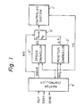
- Figure l is a block diagram of a prior art servo control system.
- the control system consists of a controlled system l ⁇ , a speed controller 2 ⁇ , a position controller 3 ⁇ , a master controller 4 ⁇ , and a switch circuit 5 ⁇ .
- the controlled system l ⁇ may include a motor for driving a controlled object, for example, a magnetic head in a magnetic disc system, a power amplifier receiving a speed control (error) signal ⁇ V from the speed controller 2 ⁇ or a position control (error) signal ⁇ P from the position controller 3 ⁇ through the switch circuit 5 ⁇ , amplifying the same, and supplying the amplified signal to the motor, and a position sensor providing a position signal PS indicating a position of the controlled object.
- error speed control
- ⁇ P position control
- the master controller 4 ⁇ receives a reference REF, such as a target cylinder (or a track) to which the magnetic head is to be moved, and a control start signal SSRT (Fig. 2b), such as a seek command from a host controller (not shown).
- a reference REF such as a target cylinder (or a track) to which the magnetic head is to be moved
- a control start signal SSRT Fig. 2b
- the master controller 4 ⁇ elects a coarse control mode and thus energizes the switch circuit 5 ⁇ by supplying a mode selection signal MS of low level thereto (Fig. 2c) so that the speed error signal ⁇ V is supplied to the controlled system l ⁇ .
- the master controller 4 ⁇ calculates a moving value SMOVE from a current position of the controlled object, such as the magnetic head, indicated by the position signal PS, to the reference REF, and issues the moving value SMOVE and energizes the speed controller 2 ⁇ .
- the speed controller 2 ⁇ receives the position signal PS and calculates an actual speed signal Vr by differentiating the position signal PS.
- the speed controller 2 ⁇ generates a reference speed Vc on the basis of the moving value SMOVE and the operational characteristics of the motor in the controller system l ⁇ .
- the speed error ⁇ V is supplied as a speed error signal to the motor through the switch circuit 5 ⁇ and the power amplifier in the controlled system l ⁇ , so that the controlled object is moved to the target track defined by the reference REF.
- the moved position of the controlled object is sensed by the position sensor in the controlled system l ⁇ .
- the position signal PS is fed back to the speed controller 2 ⁇ .
- the above closed-loop speed control may be continued until the speed of the controlled object reaches a predetermined low level, e.g., approximately zero speed.
- the master controller 2 ⁇ receives the position signal PS, calculates the speed, and judges that the speed reaches the predetermined low level.
- the above speed control provides coarse control which moves the controlled object to a position adjacent to the target track, but cannot carry out fine position control at the target track.
- the master controller 4 ⁇ issues a reference position REF P , i.e., the position of the target track, and changes the mode selection signal MS to high level (Fig. 2c) so as to connect the position controller 3 ⁇ and the controlled system l ⁇ through the switch circuit 5 ⁇ .
- fine control i.e., position control by the position controller 3 ⁇ , starts (Fig. 2d).
- the position controller 3 ⁇ normally has a PID control function and controls the controlled object to be finely positioned at the reference position REF P .
- the position controller 3 ⁇ finely controls the controlled object within an upper limit LMT U and a lower limit LMT L .
- the upper limit LMT U is, for example, +0.8 ⁇ m with respect to the reference position REF P
- the lower limit LMT L is, for example, -0.8 ⁇ m.
- the master controller 4 ⁇ supervises the position signal PS and outputs a control end signal SEND (Fig. 2e) to the host controller at a time t3 ⁇ , where the position signal PS enters a permissible positioning range defined by the limits LMT U and LMT L (Fig. 2a).
- the host controller for example, in the magnetic disc system, outputs a read command or a write command.
- the settling time is a time Tl ⁇ between the times tl ⁇ and t3 ⁇ as shown in Fig. 2f.
- the settling time Tl ⁇ indicates the seek time in the magnetic disc system.
- control parameters of the PID control algorithm are constants and are adjusted for optimal fine positioning of the controlled object in a steady state. Accordingly, the open-loop frequency characteristic is constant.
- the settling time Tl ⁇ becomes long.
- the settling time T2 ⁇ (Fig. 2a) of the position control should especially be shortened.
- a first embodiment of a servo control system applied to a magnetic disc system will be described.
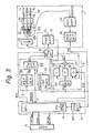
- the magnetic disc system in Fig. 3 includes a magnetic head drive system l, a speed controller 2, a position controller 3, a master controller 4 connected to a host controller 6, and a switch circuit 5.
- the magnetic head drive system l includes magnetic discs ll fixed on a rotary shaft l6, magnetic heads l2, a voice coil motor l0 driving the magnetic heads l2 in a radial direction of the magnetic discs ll, and a power amplifier l3 supplying a drive current I D to the voice coil motor l0.
- the magnetic head drive system l also includes an automatic gain control (AGC) amplifier l4 and a position signal detection circuit l5.
- the AGC amplifier l4 receives the servo signal SSERVO from the magnetic head l2c and performs the automatic gain control.
- the position signal detection circuit l5 receives an automatic-gain-controlled servo signal and outputs a position signal PS having a sine wave shape.
- the voice coil motor l0 has a linear operational characteristic.
- the power amplifier l3 outputs a current detection signal i corresponding to the drive current I D therefrom.
- the speed controller 2 functions as a coarse position controller.
- the speed controller 2 includes a reference speed generation circuit 20, a speed signal generation circuit 2l, and a speed error generation circuit 22.
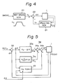
- a block diagram of a feedback speed control system constituted by the speed controller 2 and the magnetic head drive system l is given in Fig. 4.
- the reference speed generation circuit 20 receives a moving signal SMOVE which is a moving track(s) between a current track and a target track, calculated at the master controller 4, and generates a reference speed Vc having a trapezoidal shape and defined by the moving signal SMOVE and the operation characteristics of the magnetic head drive system l.
- the speed signal generation circuit 2l receives the current detection signal i from the power amplifier l3 and the position signal PS from the position signal detection circuit l5 and generates an actual moving speed Vr of the magnetic head l2c. As the actual moving speed Vr is calculated on the basis of the combination of a speed obtained by differentiating the position signal PS and the current detection signal i , the actual moving speed Vr is guaranteed a high accuracy in a wide frequency range. This will be described in more detail in the description of the position controller 3.
- the power amplifier l3 amplifies the speed control signal and supplies the drive current I D corresponding to the speed control signal to the voice coil motor l0.
- the voice coil motor l0 drives the magnetic heads l2 in response to the drive current I D .
- the current detection signal i from the power amplifier l3 and the position signal PS from the position signal detection circuit l5 are fed back to the speed controller 2 to form a closed speed control system.
- the position controller 3 functions as a fine position controller.
- the position controller 3 includes a low pass filter 30, an integration control circuit 3l, a proportional control circuit 32, a differential control circuit 33, and an adder 34.
- the low pass filter 30 receives the position signal PS from the position signal detection circuit l5 and rejects a high frequency component contained in the position signal PS.
- the filtered position signal is supplied to the control circuits 3l to 33.
- the servo signal from the magnetic head l2c indicates a positional deviation of the magnetic head l2c with respect to a target track position, and thus the position signal PS substantially indicates a positional error ⁇ x with respect to the target track position.
- the error function f( ⁇ x, i) is substantially the same as the calculation in the speed signal generator 2l and will be described in more detail with reference to the following drawings.
- the reference position REF P added to an addition point 35 is zero because the position signal PS, per se, indicates the positional error ⁇ x.
- the control signals SC P and SC I are added at an addition point 34a and further added with the control signal SC D at an addition point 34b.
- the position controller 3 provides a position control signal ⁇ P expressed by the formula (4) to the magnetic head drive system l through the switch circuit 5.
- the power amplifier l3 receives the position control signal ⁇ P and amplifies the same and supplies the drive current I D corresponding to the position control signal to the voice coil motor l0.
- the voice coil motor l0 drives the magnetic heads l2 in response to the drive current I D .
- the current detection signal i from the power amplifier l3 and the position signal PS, i.e., the position error ⁇ x, from the position signal detection circuit l5 are fed back to the position controller 3 to form a closed position control system.
- the above-mentioned position control is merely of a fundamental PID position control.
- the feature of the embodiment is to change only the differential constant K D in the differential control circuit 33 in response to a gain change signal GS from the master controller 4. This gain change will be described later.
- the master controller 4 includes a position detection circuit 40 and a microprocessor (MPU) 4l having a CPU (not shown), a RAM (not shown), a ROM (not shown), an input/output (I/O) port (not shown), and a timer 4la.
- the MPU 4l may be an INTEL 803l.
- the position detection circuit 40 receives the position signal PS indicating the servo information from the position signal detection circuit l5 and detects an actual position of the magnetic head l2c.
- the MPU 4l carries out seek control.
- the MPU 4l receives a seek command SEEK S and a target cylinder (or a target track) TRGT TRK through the I/O port.
- the MPU 4l also receives the actual position from the position signal detection circuit l5 and the actual speed Vr from the speed signal generation circuit 2l and calculates a magnetic head moving value as a moving signal SMOVE to the target track TRG TRK .
- the MPU 4l Upon receipt of the seek command SEEK S and the target track TRGT TRK from the host controller 6 at a time tl (Fig. 6b), the MPU 4l selects the speed control mode, i.e., the coarse control mode. The MPU 4l calculates the magnetic head moving value and supplies the moving signal SMOVE to the reference speed generation circuit 20. At the same time, the MPU 4l outputs a control mode change signal MS of a low level (Fig. 6c), to connect the speed control signal ⁇ V to the power amplifier l3.
- the MPU 4l When the actual speed Vr reaches a predetermined value, e.g., approximately zero, at a time t2, the MPU 4l initializes the position controller 3, more specifically, the integration control circuit 3l. Simultaneously, the MPU 4l starts the timer 4la, outputs the gain change signal GS of a high level (Fig. 6e) to only the differential control circuit 33, and outputs the control mode selection signal MS of a high level (Fig. 6c) to connect the position control signal ⁇ P to the power amplifier l3 through the switch circuit 5. The timer 4la terminates after a lapse of a time ⁇ from the time t2. Then, the MPU 4l changes the gain control signal GS to the differential control circuit 33 to a low level at a time t4 (Fig. 6e).
- a predetermined value e.g., approximately zero
- the magnetic head l2c Before reaching the time t4, the magnetic head l2c can be positioned in a permissible position region between an upper limit LMT U , for example, +0.8 ⁇ m with respect to a target track position (or a reference position) REF P , and a lower limit LMT L , for example, -0.8 ⁇ m, at a time t3.
- the MPU 4l outputs a seek completion signal SEEK C to the host controller 6. Then, the host controller 6 may request a read access or a write access.
- the feature of the present invention is to temporarily change only the differential control gain K D during the time ⁇ (Fig. 6e) in an initial state of the position control mode. Reasons of the change and effects thereof will be described.
- the PID control algorithm represented by the formula (4) can be rewritten as the following formula: where, k indicates a loop gain, T I indicates an integral time, and T D indicates a differential time.
- the open loop frequency characteristic is essen strictlytially determined by the differential gain K D . Therefore, it may also be considered to reduce the overshoot and/or undershoot and shorten the settling time Tl ⁇ or T2 ⁇ by increasing only the differential gain K D .
- the differential gain K D can only be increased to the extent where no oscillation is generated in the magnetic head drive system l, more concretely, the voice coil motor l0 at a resonance frequency thereof in a high frequency. That is, in order to avoid oscillation, the differential gain K D cannot be made too large. In particular, the differential gain K D cannot be large at all times in the entire frequency range.
- the differential gain K D must be optimized in a steady state to ensure fine position control in the steady state, where read or write access can be effected.
- the present invention increases the differential gain K D only during the time ⁇ (Fig. 6e) in the initial state of the position control to reduce the overshoot and/or undershoot and to shorten the settling time and restores the differential gain K D to the optimum value for the steady state control.
- the time ⁇ is, for example, 3 ms, sufficiently small for avoiding oscillation.
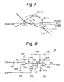
- the gain curve of the PID control is lifted only in the high frequency range, as shown by the dotted curve CVG2 from curve CVGl in Fig. 7.
- a phase margin ⁇ 2 is increased and becomes greater than the phase margin ⁇ 1. This ensures the improvement of the stability.
- curve CVP2 represents a phase when the differential gain K D is increased. In other words, at the initial state of the position control, the frequency of the servo signal is relatively low, and thus no oscillation is generated. After that, the differential gain K D is restored, thus the optimum control can be maintained in a high frequency range.
- the gain changeable differential control circuit 33 is shown in Fig. 8.
- the differential control circuit 33 includes a differential circuit 33a consisting of a capacitor 33l having a capacitance Cl, a resistor 34l having a resistance Rl, an operational amplifier 35l, a bias resistor 343 having a resistance R3, a feedback resistor 342 having a resistance R2, and a feedback capacitor 332 having a capacitance C2.
- the differential control circuit 33 also includes a gain change circuit 33b consisting of a switch 353, a resistor 344 having a resistance R4, and a resistor 345 having a resistance R5.
- the differential control circuit 33 further includes an addition circuit 33c consisting of an input resistor 346 having a resistance R6, an operational amplifier 352, a bias resistor 348 having a resistance R8, a feedback resistor 347 having a resistance R7, and a feedback capacitor 333 having a capacitance C3.
- the position signal PS is differentiated by a differentiator of the series-connected capacitor 33l and the resistor 34l.
- a voltage V Nl at a node Nl is defined by the following formula:
- the addition circuit 33c adds the current detection signal i supplied to the resistor 346 and the differentiated position signal supplied to a node N2 through the resistor 344 and outputs the differential control signal SC D at a node N3.
- the combination of the differentiated position signal and the current detection signal i ensures reliability of control over a wide frequency range.
- the differential gain K D combined with al and a2 when the gain change signal GS of a high level is supplied is greater than the differential gain K ⁇ D when the gain change signal GS of a high level is removed.
- the differential time of the capacitor 33l and the resistor 34l is approximately 6.6 ⁇ s.
- curve Fa represents a gain, i.e., the open loop frequency characteristic when the switch 353 is opened.
- Curve Fb represents the open loop frequency characteristic when the switch 353 is closed at the initial state of the position control.
- ⁇ represents a phase characteristic.
- the time Tl0 in Fig. 6a is approximately l.0 to l.5 ms and the time Tll is approximately 3 to 6 ms.
- the time Tll is substantially equal to a time Tll ⁇ in Fig. 2a.
- the settling time for the position control is shortened to Tl0 from the time T2 ⁇ in Fig. 2a.
- the seek time i.e., a settling time of the speed control and position control
- the undershoot is reduced, as shown in Fig. 6a. No overshoot is generated.
- the MPU 4l can output the gain change signal GS when the magnetic head l2c reaches the permissible region between the upper limit LMT U and the lower limit LMT L and a position change with time is small, instead of waiting for the time ⁇ to elapse by the timer 4la.
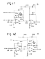
- gain changeable differential control circuit A variety of modifications of the gain changeable differential control circuit can be used.
- the differential coefficient ⁇ in the formula (6) can be changed by changing the resistance of the differential circuit of the capacitor 33l and resistors 34l ⁇ and 345 ⁇ .
- the resistance R5 ⁇ of the resistor 345 ⁇ is 6.6 k ⁇ .
- the feedback resistor of the amplifier 35l consisting of a resistor 342 ⁇ having a resistance R2 ⁇ and a resistor 349 having a resistance R9, can be changed.
- a switch 353 ⁇ is reversely energized.
- the resistor 349 is connected to the resistor 342 ⁇ in series.
- the resistor 349 is bypassed in the steady state.
- the amplification factor of the amplifier 35l is changed.
- the change of the amplification factor is substantially equal to the change of the differential coefficient u.
- the feedback resistor of the amplifier 352 consisting of a resistor 347 ⁇ having a resistance R7 ⁇ and a resistor 349 ⁇ having a resistance R9 ⁇ , can be changed.
- a2 is the amplification factor for the current detection signal i in the initial state of the position control.
- a2 ⁇ is the amplification factor in the steady state.
- the speed controller 2 and the position controller 3 can be realized by a digital signal processor of high speed or the like.
- the above embodiments can be easily applied to head positioning of an optical disc system, head positioning of a serial printer, positioning of an industrial robot system, positioning a plotter, etc.
- Figure l3 shows a general control system with a changeable differential gain K D .
- the master controller 4a is optional in the present invention.
- the fine controller 3a receives the reference position REF.
- the position control may be realized by not only PID control but also PD control, or ID control.
- the differential gain can be changed not only twice, but three times or more. Especially, in a control system where the settling time is considerably long due to large inertia of the controlled system, a plurality of steps of gain change in a transient state are preferable.
Landscapes
- Engineering & Computer Science (AREA)
- Physics & Mathematics (AREA)
- General Physics & Mathematics (AREA)
- Automation & Control Theory (AREA)
- Human Computer Interaction (AREA)
- Manufacturing & Machinery (AREA)
- Control Of Position Or Direction (AREA)
- Moving Of Head For Track Selection And Changing (AREA)
Applications Claiming Priority (2)
| Application Number | Priority Date | Filing Date | Title |
|---|---|---|---|
| JP213005/86 | 1986-09-10 | ||
| JP61213005A JPS6368913A (ja) | 1986-09-10 | 1986-09-10 | サ−ボ制御回路 |
Publications (3)
| Publication Number | Publication Date |
|---|---|
| EP0260138A2 true EP0260138A2 (de) | 1988-03-16 |
| EP0260138A3 EP0260138A3 (en) | 1989-05-31 |
| EP0260138B1 EP0260138B1 (de) | 1993-07-14 |
Family
ID=16631909
Family Applications (1)
| Application Number | Title | Priority Date | Filing Date |
|---|---|---|---|
| EP87308010A Expired - Lifetime EP0260138B1 (de) | 1986-09-10 | 1987-09-10 | Servosteuerungssystem |
Country Status (5)
| Country | Link |
|---|---|
| US (1) | US4924165A (de) |
| EP (1) | EP0260138B1 (de) |
| JP (1) | JPS6368913A (de) |
| KR (1) | KR900005550B1 (de) |
| DE (1) | DE3786508T2 (de) |
Cited By (7)
| Publication number | Priority date | Publication date | Assignee | Title |
|---|---|---|---|---|
| EP0343332A1 (de) * | 1988-05-26 | 1989-11-29 | Mitsubishi Denki Kabushiki Kaisha | Gerät für den Antrieb magnetischer Platten |
| EP0344958A1 (de) * | 1988-05-31 | 1989-12-06 | Kabushiki Kaisha Toshiba | Kopfsteuerungsschaltung |
| FR2642866A1 (fr) * | 1989-01-11 | 1990-08-10 | Inst Mash Im | Procede de commande d'un bras mecanique a resonance |
| EP0360490A3 (en) * | 1988-09-19 | 1990-09-26 | Hewlett-Packard Company | Hybrid sample rate servo motor controller |
| GB2231976A (en) * | 1989-04-24 | 1990-11-28 | Mitsubishi Electric Corp | Position control |
| GB2308464A (en) * | 1995-12-20 | 1997-06-25 | Samsung Electronics Co Ltd | Drive system for a voice control motor |
| EP1332494A4 (de) * | 2000-09-21 | 2005-04-20 | Gsi Lumonics Corp | Digitales steuer-servosystem |
Families Citing this family (17)
| Publication number | Priority date | Publication date | Assignee | Title |
|---|---|---|---|---|
| JP2613937B2 (ja) * | 1989-01-30 | 1997-05-28 | 富士通株式会社 | サーボ回路 |
| US5371636A (en) * | 1990-03-30 | 1994-12-06 | Archive Corporation | Mechanisms for a closed loop head positioner for streaming tape drives |
| JP2685622B2 (ja) * | 1990-04-06 | 1997-12-03 | 株式会社日立製作所 | 位置決め制御方法および装置 |
| JPH0792702B2 (ja) * | 1990-07-17 | 1995-10-09 | 株式会社三協精機製作所 | 制御装置 |
| US5097744A (en) * | 1991-01-14 | 1992-03-24 | General Electric Company | Hydraulic control system |
| US5245698A (en) * | 1991-08-14 | 1993-09-14 | Omron Corporation | Apparatus for and method of correcting membership functions |
| JP2996545B2 (ja) * | 1991-08-30 | 2000-01-11 | キヤノン株式会社 | モータ制御方法及び装置 |
| KR20020001742A (ko) | 1999-02-22 | 2002-01-09 | 추후 | 반복 가능한 런아웃 에러 보상 |
| WO2000068939A1 (en) | 1999-05-07 | 2000-11-16 | Seagate Technology Llc | Repeatable runout compensation using iterative learning control in a disc storage system |
| US6437936B1 (en) | 1999-07-23 | 2002-08-20 | Seagate Technology Llc | Repeatable runout compensation using a learning algorithm with scheduled parameters |
| US6952320B1 (en) | 1999-12-16 | 2005-10-04 | Seagate Technology Llc | Virtual tracks for repeatable runout compensation |
| JP3869998B2 (ja) * | 2000-03-24 | 2007-01-17 | パイオニア株式会社 | キャリッジサーボ装置及び情報再生装置 |
| JP3832712B2 (ja) * | 2000-09-21 | 2006-10-11 | セイコーエプソン株式会社 | 印刷制御装置および制御方法ならびに印刷制御プログラムを記録した記録媒体 |
| GB0313887D0 (en) | 2003-06-16 | 2003-07-23 | Gsi Lumonics Ltd | Monitoring and controlling of laser operation |
| US7401880B1 (en) * | 2004-01-09 | 2008-07-22 | Sigmatel, Inc. | Combination of A/D inputs with quadrature detection to give higher resolution positioning |
| EP1706801A1 (de) | 2004-01-23 | 2006-10-04 | GSI Group Corporation | System und verfahren zur diagnostizierung einer steuerung in einem motorsystem mit begrenzter drehung |
| JP5707129B2 (ja) * | 2010-12-28 | 2015-04-22 | Thk株式会社 | モータ制御装置、モータ制御方法、及び制御プログラム |
Family Cites Families (20)
| Publication number | Priority date | Publication date | Assignee | Title |
|---|---|---|---|---|
| US3721882A (en) * | 1971-06-25 | 1973-03-20 | Sperry Rand Corp | Positioning system |
| US4006394A (en) * | 1972-08-21 | 1977-02-01 | Information Storage Systems, Inc. | Coarse and fine control for position servo |
| FR2336768A1 (fr) * | 1975-12-24 | 1977-07-22 | Honeywell Bull Soc Ind | Procede pour deplacer un systeme mobile par rapport a un support d'enregistrement d'informations et dispositif pour le mettre en oeuvre |
| DE2640861A1 (de) * | 1976-09-10 | 1978-03-16 | Siemens Ag | Regeleinrichtung |
| US4069413A (en) * | 1976-10-29 | 1978-01-17 | Phillips Petroleum Company | Process measurement and control |
| JPS547078A (en) * | 1977-06-16 | 1979-01-19 | Oki Electric Ind Co Ltd | Automatic positioning method to inherent position of machine in numerical control |
| US4200827A (en) * | 1977-06-29 | 1980-04-29 | International Business Machines Corporation | Positioning system employing feedforward and feedback control |
| US4184108A (en) * | 1977-11-23 | 1980-01-15 | Sperry Rand Corporation | Self-regulating electronic tachometer |
| JPS57106383A (en) * | 1980-12-20 | 1982-07-02 | Ricoh Co Ltd | Controlling method for stoppage of servomotor and its control circuit |
| US4429267A (en) * | 1981-06-22 | 1984-01-31 | Manhattan Engineering Company, Inc. | Digital positioning systems having high accuracy |
| JPS57211612A (en) * | 1981-06-23 | 1982-12-25 | Sony Corp | Phase servo circuit |
| US4491776A (en) * | 1982-05-25 | 1985-01-01 | Manhattan Engineering Company, Inc. | Servo operated digital positioning control system |
| US4577097A (en) * | 1982-09-03 | 1986-03-18 | The Babcock & Wilcox Company | Three-mode analog controller with remote tuning |
| US4480217A (en) * | 1982-12-14 | 1984-10-30 | Storage Technology Corporation | Automatic velocity calibrator for a velocity servo loop in a magnetic disk drive |
| JPS59189401A (ja) * | 1983-04-13 | 1984-10-27 | Fanuc Ltd | 位置制御装置 |
| SE442851B (sv) * | 1983-04-18 | 1986-02-03 | Saab Scania Ab | Forfarande och anordning vid styrsystem |
| JPS59231615A (ja) * | 1983-06-13 | 1984-12-26 | Fanuc Ltd | 位置ル−プゲイン制御方法 |
| US4551664A (en) * | 1983-09-27 | 1985-11-05 | Mechatron Systems, Inc. | Velocity-position servo with improved gain control |
| JPS6139275A (ja) * | 1984-07-30 | 1986-02-25 | Fujitsu Ltd | 磁気デイスク装置用閉ル−プ制御回路 |
| US4810941A (en) * | 1986-04-17 | 1989-03-07 | Canon Kabushiki Kaisha | Control system for a servomotor |
-
1986
- 1986-09-10 JP JP61213005A patent/JPS6368913A/ja active Pending
-
1987
- 1987-09-10 DE DE87308010T patent/DE3786508T2/de not_active Expired - Fee Related
- 1987-09-10 EP EP87308010A patent/EP0260138B1/de not_active Expired - Lifetime
- 1987-09-10 KR KR8710041A patent/KR900005550B1/ko not_active Expired
-
1989
- 1989-01-23 US US07/300,185 patent/US4924165A/en not_active Expired - Lifetime
Cited By (11)
| Publication number | Priority date | Publication date | Assignee | Title |
|---|---|---|---|---|
| EP0343332A1 (de) * | 1988-05-26 | 1989-11-29 | Mitsubishi Denki Kabushiki Kaisha | Gerät für den Antrieb magnetischer Platten |
| US5041927A (en) * | 1988-05-26 | 1991-08-20 | Mitsubishi Denki Kabushiki Kaisha | Magnetic disc driving apparatus having speed and position control |
| EP0344958A1 (de) * | 1988-05-31 | 1989-12-06 | Kabushiki Kaisha Toshiba | Kopfsteuerungsschaltung |
| US4988933A (en) * | 1988-05-31 | 1991-01-29 | Kabushiki Kaisha Toshiba | Head driving circuit |
| EP0360490A3 (en) * | 1988-09-19 | 1990-09-26 | Hewlett-Packard Company | Hybrid sample rate servo motor controller |
| FR2642866A1 (fr) * | 1989-01-11 | 1990-08-10 | Inst Mash Im | Procede de commande d'un bras mecanique a resonance |
| GB2231976A (en) * | 1989-04-24 | 1990-11-28 | Mitsubishi Electric Corp | Position control |
| GB2308464A (en) * | 1995-12-20 | 1997-06-25 | Samsung Electronics Co Ltd | Drive system for a voice control motor |
| GB2308464B (en) * | 1995-12-20 | 1998-03-11 | Samsung Electronics Co Ltd | Drive control circuit for a voice coil motor |
| EP1332494A4 (de) * | 2000-09-21 | 2005-04-20 | Gsi Lumonics Corp | Digitales steuer-servosystem |
| US7200464B2 (en) | 2000-09-21 | 2007-04-03 | Gsi Group Corporation | Digital control servo system |
Also Published As
| Publication number | Publication date |
|---|---|
| KR900005550B1 (en) | 1990-07-31 |
| US4924165A (en) | 1990-05-08 |
| EP0260138A3 (en) | 1989-05-31 |
| KR880004361A (ko) | 1988-06-03 |
| DE3786508T2 (de) | 1993-11-18 |
| EP0260138B1 (de) | 1993-07-14 |
| JPS6368913A (ja) | 1988-03-28 |
| DE3786508D1 (de) | 1993-08-19 |
Similar Documents
| Publication | Publication Date | Title |
|---|---|---|
| EP0260138B1 (de) | Servosteuerungssystem | |
| EP0408392B1 (de) | Aufnahme- und Wiedergabegerät für optische Scheibe | |
| EP0000261B1 (de) | Schaltung zur direkten und rückgekoppelten Steuerung einer Positioniereinrichtung | |
| EP1278109B1 (de) | Abgestimmtes offenes Regelkreisverfahren, das in ein geschlossenes Regelkreisverfahren umgeschaltet wird, für schnelle Punkt-zu-Punkt-Bewegungen in einer periodischen Bewegungsregeleinrichtung | |
| US4321517A (en) | Resonance suppression method | |
| JP3377013B2 (ja) | ディスク装置のシーク制御装置及びそれを用いたシーク制御方法 | |
| JP2759686B2 (ja) | 記録担体を走査する装置 | |
| EP0622783B1 (de) | Servoschaltungsanordnung für ein Magnetplattenlaufwerk | |
| US5912542A (en) | Variable load inductance compensation for motor drive circuits | |
| US5305158A (en) | Positioning control apparatus | |
| US5231625A (en) | Optical disk drive wherein a preset reading laser power is used to generate a desired white laser power | |
| US5566145A (en) | Head tracking system in a disk drive | |
| US4827200A (en) | Velocity control unit of detecting head | |
| US5258966A (en) | Positioner seek control system of a disk apparatus and method for scanning a beam across a medium | |
| US5010425A (en) | Access controller for controlling the seek operation of a head relative to a recording medium | |
| EP0196543A2 (de) | Stromregelung für eine induktive Last | |
| HK7195A (en) | Automatic gain control circuit for a control amplifier | |
| US5138595A (en) | Servo control circuit for optical disc apparatus | |
| US6166597A (en) | Method for feedback control of a controlled variable | |
| JPH06187655A (ja) | 光ディスク装置 | |
| JP3853635B2 (ja) | ディスク制御装置 | |
| JPS6283503A (ja) | デイジタル弁クロ−ズドル−プ制御装置 | |
| JP2599989B2 (ja) | 磁気ディスク装置とそのサーボ回路調整方法 | |
| EP0746888A1 (de) | Laser-stromversorgungsschaltung sowie ein eine solche schaltung enthaltendes optisches aufzeichnungs- und/oder lesegerät | |
| JPH0349037A (ja) | 光ディスク装置におけるアクセス制御装置 |
Legal Events
| Date | Code | Title | Description |
|---|---|---|---|
| PUAI | Public reference made under article 153(3) epc to a published international application that has entered the european phase |
Free format text: ORIGINAL CODE: 0009012 |
|
| AK | Designated contracting states |
Kind code of ref document: A2 Designated state(s): DE FR GB NL |
|
| PUAL | Search report despatched |
Free format text: ORIGINAL CODE: 0009013 |
|
| RHK1 | Main classification (correction) |
Ipc: G05B 19/19 |
|
| AK | Designated contracting states |
Kind code of ref document: A3 Designated state(s): DE FR GB NL |
|
| 17P | Request for examination filed |
Effective date: 19891023 |
|
| 17Q | First examination report despatched |
Effective date: 19911025 |
|
| GRAA | (expected) grant |
Free format text: ORIGINAL CODE: 0009210 |
|
| AK | Designated contracting states |
Kind code of ref document: B1 Designated state(s): DE FR GB NL |
|
| REF | Corresponds to: |
Ref document number: 3786508 Country of ref document: DE Date of ref document: 19930819 |
|
| ET | Fr: translation filed | ||
| PLBE | No opposition filed within time limit |
Free format text: ORIGINAL CODE: 0009261 |
|
| STAA | Information on the status of an ep patent application or granted ep patent |
Free format text: STATUS: NO OPPOSITION FILED WITHIN TIME LIMIT |
|
| 26N | No opposition filed | ||
| PGFP | Annual fee paid to national office [announced via postgrant information from national office to epo] |
Ref country code: NL Payment date: 19970929 Year of fee payment: 11 |
|
| PG25 | Lapsed in a contracting state [announced via postgrant information from national office to epo] |
Ref country code: NL Free format text: LAPSE BECAUSE OF NON-PAYMENT OF DUE FEES Effective date: 19990401 |
|
| NLV4 | Nl: lapsed or anulled due to non-payment of the annual fee |
Effective date: 19990401 |
|
| REG | Reference to a national code |
Ref country code: GB Ref legal event code: IF02 |
|
| PGFP | Annual fee paid to national office [announced via postgrant information from national office to epo] |
Ref country code: FR Payment date: 20030909 Year of fee payment: 17 |
|
| PGFP | Annual fee paid to national office [announced via postgrant information from national office to epo] |
Ref country code: GB Payment date: 20030910 Year of fee payment: 17 |
|
| PGFP | Annual fee paid to national office [announced via postgrant information from national office to epo] |
Ref country code: DE Payment date: 20030918 Year of fee payment: 17 |
|
| PG25 | Lapsed in a contracting state [announced via postgrant information from national office to epo] |
Ref country code: GB Free format text: LAPSE BECAUSE OF NON-PAYMENT OF DUE FEES Effective date: 20040910 |
|
| PG25 | Lapsed in a contracting state [announced via postgrant information from national office to epo] |
Ref country code: DE Free format text: LAPSE BECAUSE OF NON-PAYMENT OF DUE FEES Effective date: 20050401 |
|
| GBPC | Gb: european patent ceased through non-payment of renewal fee |
Effective date: 20040910 |
|
| PG25 | Lapsed in a contracting state [announced via postgrant information from national office to epo] |
Ref country code: FR Free format text: LAPSE BECAUSE OF NON-PAYMENT OF DUE FEES Effective date: 20050531 |
|
| REG | Reference to a national code |
Ref country code: FR Ref legal event code: ST |