EP0344958A1 - Kopfsteuerungsschaltung - Google Patents
Kopfsteuerungsschaltung Download PDFInfo
- Publication number
- EP0344958A1 EP0344958A1 EP89305178A EP89305178A EP0344958A1 EP 0344958 A1 EP0344958 A1 EP 0344958A1 EP 89305178 A EP89305178 A EP 89305178A EP 89305178 A EP89305178 A EP 89305178A EP 0344958 A1 EP0344958 A1 EP 0344958A1
- Authority
- EP
- European Patent Office
- Prior art keywords
- driving circuit
- voice coil
- coil motor
- gain
- signal
- Prior art date
- Legal status (The legal status is an assumption and is not a legal conclusion. Google has not performed a legal analysis and makes no representation as to the accuracy of the status listed.)
- Withdrawn
Links
- 230000003287 optical effect Effects 0.000 claims description 3
- 238000010586 diagram Methods 0.000 description 3
- 230000002411 adverse Effects 0.000 description 2
- 230000000694 effects Effects 0.000 description 2
- 230000007423 decrease Effects 0.000 description 1
- 230000003247 decreasing effect Effects 0.000 description 1
- 230000010365 information processing Effects 0.000 description 1
Images

Classifications
-
- G—PHYSICS
- G11—INFORMATION STORAGE
- G11B—INFORMATION STORAGE BASED ON RELATIVE MOVEMENT BETWEEN RECORD CARRIER AND TRANSDUCER
- G11B7/00—Recording or reproducing by optical means, e.g. recording using a thermal beam of optical radiation by modifying optical properties or the physical structure, reproducing using an optical beam at lower power by sensing optical properties; Record carriers therefor
- G11B7/08—Disposition or mounting of heads or light sources relatively to record carriers
- G11B7/085—Disposition or mounting of heads or light sources relatively to record carriers with provision for moving the light beam into, or out of, its operative position or across tracks, otherwise than during the transducing operation, e.g. for adjustment or preliminary positioning or track change or selection
- G11B7/08505—Methods for track change, selection or preliminary positioning by moving the head
- G11B7/08517—Methods for track change, selection or preliminary positioning by moving the head with tracking pull-in only
-
- G—PHYSICS
- G11—INFORMATION STORAGE
- G11B—INFORMATION STORAGE BASED ON RELATIVE MOVEMENT BETWEEN RECORD CARRIER AND TRANSDUCER
- G11B21/00—Head arrangements not specific to the method of recording or reproducing
- G11B21/02—Driving or moving of heads
- G11B21/08—Track changing or selecting during transducing operation
- G11B21/081—Access to indexed tracks or parts of continuous track
- G11B21/083—Access to indexed tracks or parts of continuous track on discs
- G11B21/085—Access to indexed tracks or parts of continuous track on discs with track following of accessed part
-
- G—PHYSICS
- G11—INFORMATION STORAGE
- G11B—INFORMATION STORAGE BASED ON RELATIVE MOVEMENT BETWEEN RECORD CARRIER AND TRANSDUCER
- G11B5/00—Recording by magnetisation or demagnetisation of a record carrier; Reproducing by magnetic means; Record carriers therefor
- G11B5/48—Disposition or mounting of heads or head supports relative to record carriers ; arrangements of heads, e.g. for scanning the record carrier to increase the relative speed
- G11B5/54—Disposition or mounting of heads or head supports relative to record carriers ; arrangements of heads, e.g. for scanning the record carrier to increase the relative speed with provision for moving the head into or out of its operative position or across tracks
- G11B5/55—Track change, selection or acquisition by displacement of the head
- G11B5/5521—Track change, selection or acquisition by displacement of the head across disk tracks
- G11B5/5526—Control therefor; circuits, track configurations or relative disposition of servo-information transducers and servo-information tracks for control thereof
- G11B5/553—Details
Definitions
- the present invention relates to a head driving circuit used for a magnetic disk unit or the like.
- an information processing apparatus such as a personal computer employs an information recording and reproducing unit such as a magnetic disk unit or an optical disk unit as an external storage unit.
- the magnetic disk unit has a head positioning mechanism which serves to position a magnetic head loaded on a carriage assembly at a given position on a recording surface of a magnetic disk when a command is issued from a personal computer.
- the moving system of such a carriage assembly can employ a swing arm type or a linear type.
- the driving system used in the type employs a voice coil motor or a stepping motor.
- a voice coil motor driving circuit for the voice coil motor is done largely in two modes, that is, a moving (speed) control mode and a track-following (position) control mode.
- the foregoing conventional voice coil motor driving circuit in the moving control mode, must supply larger exciting current to an exciting coil in a moving control mode. It results in providing the signal (ACTDRV) for driving the voice coil motor with a relatively large signal voltage waveform amplitude.
- the voice coil motor driving circuit supplies exciting current equal to essentially zero to the exciting coil. It results in providing the signal (ACTDRV) for driving the voice coil motor with a relatively small signal voltage waveform amplitude.
- the voice coil motor driving circuit is required to achieve the operation accuracy, especially in the track-following control mode.
- the present invention is designed to overcome the foregoing disadvantage, and it is an object of the invention to provide a head driving circuit which can stably and reliably record or reproduce information on a recording medium.
- the invention comprises a voice coil motor for moving a head for reading information from a disk or writing it thereon, a driving means for supplying current to the voice coil motor in response to a first control signal, and a gain control means for changing a gain of the driving means in response to a second control signal.
- the gain control means can switch the gain of the driving means in a stepwise manner, thereby stably positioning a head. It can stably and reliably record information on a recording medium or reproduce it therefrom. Moreover, since this head driving circuit can avoid an adverse effect resulting form variations of elements such as resistors and of an input offset voltage of a power operational amplifier, it can endure less accurate elements, resulting in contributing on lowering the overall cost.
- Fig.1 is a circuit diagram showing a voice coil motor driving circuit showing one embodiment in which the invention applied to a magnetic disk unit; and Fig.2 is a circuit diagram showing a voice coil motor driving circuit used in a conventional magnetic disk unit.
- Fig.1 shows one embodiment of a voice coil motor driving circuit in which the invention is applied to a magnetic disk unit
- the voice coil motor driving circuit comprises a voice coil motor 5 equipped with a center tap containing exciting coils 1 and 3.
- a collector of the transistor 7 for controlling the amount of the exciting current I0 supplied from a reference power source V cc .
- a base of the transistor 7 is connected to a power operational amplifier 9.
- a non-reverse input terminal(+) of the power operational amplifier 9 At a non-reverse input terminal(+) of the power operational amplifier 9 are connected a line 11 for transferring a positive polarity signal of the signal ACTDRV to be supplied from a control unit to be described later, and a resistor 13 for defining a gain of the voice coil motor driving circuit. At the non-reverse input terminal(+) is connected a resistor 15 for defining the gain of the voice coil motor driving circuit.
- a reverse input terminal(-) thereof is connected a built-in reference power source VN through a resistor 19 for defining the gain of the voice coil motor driving circuit.
- a resistor 21 for defining the gain of the voice coil motor driving circuit and a line 23.
- the resistors 13 and 19 respectively have r11 values, and the resistors 15 and 12 respectively have r12 values.
- a collector of the transistor 25 for controlling the amount of the exciting current I0 to be supplied from the reference power source V cc to the exciting coil 3.
- a base of the transistor 25 is connected to a power operational amplifier 27.
- a resistor 31 for defining a gain of the voice coil motor driving circuit and a line 29 for transferring a negative polarity signal of the signal ACTDRV.
- a resistor 33 At a reverse input terminal(-) of the power operational amplifier is connected to a resistor 33.
- a non-reverse input terminal(+) thereof is connected a built-in reference power source VN through a resistor 35 for defining a gain of the voice coil motor driving circuit. And, at the non-reverse input terminal(+) is connected a resistor 37 for defining the gain of the voice coil motor driving circuit.
- the resistors 31 and 35 respectively have r21 values, and the resistors 33 and 37 respectively have r22 values.
- a resistor 39 whose resistance is R is connected to each emitter of the transistors 7 and 25 and the line 23.
- One end of the resistor 39 is connected in parallel with a resistor 51 whose resistance is R A .
- the other end of the resistor 51 is connected to the ground with a transistor 53.
- a control unit 45 supplies a signal GAINCUT to the base of the transistor 53 in such a way that the transistor 53 is conductive in case of a high-level signal GAINCUT and is not conductive in case of a low-level one.
- a speed sensor 41 and a position sensor 43 respectively detect a speed and a position of a head (not shown) and send them to the control unit 45.
- the control unit 45 sends a signal ACTDRV for driving a head through a D/A converter 47.
- the signal GAINCUT is at low level in a track-following control mode and at high level in a moving control mode.
- the voice coil motor driving circuit having the foregoing arrangement is operated as follows.
- the control unit 45 applies a positive polarity voltage of the signal ACTDRV into the non-reverse input terminal(+) of the power operational amplifier 9.
- the power operational amplifier 9 serves to amplify the difference between the voltage of the signal ACTDRV and the voltage applied at the reverse input terminal(-) by the built-in reference power source VN and to output the result to the transistor 7.
- the transistor 7 controls the amount of the exciting current I0 supplied from the reference power source V cc to the exciting coil side 1 on the basis of the magnitude of the signal voltage applied to the base of the transistor 7 itself.
- the power operational amplifier 27 When a negative polarity voltage of the signal ACTDRV is applied at the reverse input terminal(-) of the power operational amplifier 27 through the line 29, on the other hand, the power operational amplifier 27 through the line 29, on the other hand, the power operational amplifier 27 serves to amplify the difference between the voltage of the signal ACTDRV and the voltage applied from the built-in reference power source VN to the non-reverse input terminal(+). Then, the transistor 25 serves to control the amount of the exciting current I0 supplied from the reference power source V cc exciting coil side 3 on the basis of the magnitude of the signal voltage applied on the base of the transistor 25 itself.
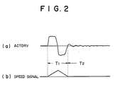
- Figs.2(a) and (b) are waveform diagram showing the signal ACTDRV and the head speed signal sent from the control unit 45.
- a period T1 denotes a moving control mode period
- a period T2 defined thereafter denotes a position control mode period.
- the signal ACTDRV in the moving control mode, the signal ACTDRV has a large absolute value, but in the position control mode, it has a small value.
- the head speed is controlled in such a way that it increases at the first half of the period T1 and decreases at the latter half and keeps constant at the period T2.
- control unit 45 applies the signal GAINCUT at low level in the track-following control mode and that at high level in the moving control mode.
- the gain G of the voice coil motor driving circuit has the relation G OFF ⁇ G ON.
- the present embodiment is designed to connect the resistors 51 and 39 in parallel and makes it possible to allow the transistor 53 to switch the gain G from the track-following control mode to the moving control mode or vice versa.
- the moving control mode therefore, by increasing the gain G, it is possible to saturate the voice coil motor driving circuit.
- the track-following control mode by decreasing the gain G, it is possible to improve the operation accuracy of the voice coil motor driving circuit with minimal current.
- a dynamic range of an input side for the signal ACTDRV can be adjusted so as to avoid an adverse effect resulting from variations of a resistance value r11 or r12 of each resistor and an input offset voltage of each power operational amplifier 9 or 27.
- This embodiment describes the magnetic disk unit to which the present invention is applied, but the invention may be applied to another information recording and reproducing apparatus such as an optical disk unit.
Landscapes
- Moving Of The Head To Find And Align With The Track (AREA)
- Control Of Linear Motors (AREA)
- Moving Of Head For Track Selection And Changing (AREA)
Applications Claiming Priority (2)
| Application Number | Priority Date | Filing Date | Title |
|---|---|---|---|
| JP63133625A JP2672574B2 (ja) | 1988-05-31 | 1988-05-31 | 情報記録再生装置 |
| JP133625/88 | 1988-05-31 |
Publications (1)
| Publication Number | Publication Date |
|---|---|
| EP0344958A1 true EP0344958A1 (de) | 1989-12-06 |
Family
ID=15109193
Family Applications (1)
| Application Number | Title | Priority Date | Filing Date |
|---|---|---|---|
| EP89305178A Withdrawn EP0344958A1 (de) | 1988-05-31 | 1989-05-23 | Kopfsteuerungsschaltung |
Country Status (3)
| Country | Link |
|---|---|
| US (1) | US4988933A (de) |
| EP (1) | EP0344958A1 (de) |
| JP (1) | JP2672574B2 (de) |
Cited By (2)
| Publication number | Priority date | Publication date | Assignee | Title |
|---|---|---|---|---|
| GB2308464A (en) * | 1995-12-20 | 1997-06-25 | Samsung Electronics Co Ltd | Drive system for a voice control motor |
| EP0989549A1 (de) * | 1998-09-21 | 2000-03-29 | Texas Instruments Incorporated | Verfahren und Gerät zur Steuerung des Motors eines Aktuators in einer Plattenlaufwerk |
Families Citing this family (15)
| Publication number | Priority date | Publication date | Assignee | Title |
|---|---|---|---|---|
| JPH0736131B2 (ja) * | 1989-01-10 | 1995-04-19 | 富士通株式会社 | サーボ回路 |
| US5194798A (en) * | 1989-01-10 | 1993-03-16 | Fujitsu Limited | Servo circuit control method and system |
| JPH0736130B2 (ja) * | 1989-01-10 | 1995-04-19 | 富士通株式会社 | サーボ位置決め回路 |
| US5204932A (en) * | 1989-01-10 | 1993-04-20 | Fujitsu Limited | Servo circuit for magnetic disk apparatus |
| US5289097A (en) * | 1992-08-18 | 1994-02-22 | International Business Machines Corporation | Spindle control method and apparatus for disk drive |
| US5343131A (en) * | 1993-01-27 | 1994-08-30 | Fujitsu Limited | Method and apparatus for self-synchronizing seek deceleration |
| US5485323A (en) * | 1993-07-14 | 1996-01-16 | International Business Machines Corporation | Method and apparatus for moving a disk drive actuator away from a magnetic latch |
| US5544160A (en) * | 1994-12-30 | 1996-08-06 | At&T Corp. | Terabit per second packet switch |
| KR100277073B1 (ko) * | 1995-07-24 | 2001-01-15 | 윤종용 | 자기 디스크 구동장치에서 자기 헤드의 속도 및 위치 추정기 |
| US6151186A (en) * | 1996-10-03 | 2000-11-21 | Texas Instruments Incorporated | Trim circuitry and method for accuracy improvement in current sensing for a voice coil driver of the type used to move read/write heads in a hard disk drive, or the like |
| US5898286A (en) * | 1997-01-13 | 1999-04-27 | International Business Machines Corporation | Digital servo control system for a data recording disk file with improved saturation modelling |
| US20020021526A1 (en) * | 1997-12-04 | 2002-02-21 | Evert S. Cooper | Method and apparatus for controlling a voice coil motor of a hard disk drive |
| US6169382B1 (en) | 1998-07-02 | 2001-01-02 | Seagate Technology Llc | Adapting seek velocity profile to destination track location |
| JP4799761B2 (ja) * | 2001-05-28 | 2011-10-26 | オンセミコンダクター・トレーディング・リミテッド | ステッピングモータの制御方法 |
| US8394088B2 (en) * | 2008-07-10 | 2013-03-12 | Hs West Investments, Llc | Electrosurgical instrument with an ablation mode and a coagulation mode |
Citations (3)
| Publication number | Priority date | Publication date | Assignee | Title |
|---|---|---|---|---|
| EP0249020A2 (de) * | 1986-06-09 | 1987-12-16 | International Business Machines Corporation | Adaptives Regelungsverfahren für ein dynamisches System |
| EP0260138A2 (de) * | 1986-09-10 | 1988-03-16 | Fujitsu Limited | Servosteuerungssystem |
| EP0265287A2 (de) * | 1986-10-24 | 1988-04-27 | Pioneer Electronic Corporation | Servovorrichtung für einen Schlitten |
Family Cites Families (3)
| Publication number | Priority date | Publication date | Assignee | Title |
|---|---|---|---|---|
| USRE32075E (en) * | 1980-09-24 | 1986-01-28 | Quantum Corporation | Data transducer position control system for rotating disk data storage equipment |
| US4535372A (en) * | 1983-06-29 | 1985-08-13 | Storage Technology Corporation | Position tracking servo control systems and methods |
| JPH0750529B2 (ja) * | 1986-05-30 | 1995-05-31 | 株式会社日立製作所 | 光学式デイスク再生装置 |
-
1988
- 1988-05-31 JP JP63133625A patent/JP2672574B2/ja not_active Expired - Lifetime
-
1989
- 1989-05-19 US US07/353,943 patent/US4988933A/en not_active Expired - Lifetime
- 1989-05-23 EP EP89305178A patent/EP0344958A1/de not_active Withdrawn
Patent Citations (3)
| Publication number | Priority date | Publication date | Assignee | Title |
|---|---|---|---|---|
| EP0249020A2 (de) * | 1986-06-09 | 1987-12-16 | International Business Machines Corporation | Adaptives Regelungsverfahren für ein dynamisches System |
| EP0260138A2 (de) * | 1986-09-10 | 1988-03-16 | Fujitsu Limited | Servosteuerungssystem |
| EP0265287A2 (de) * | 1986-10-24 | 1988-04-27 | Pioneer Electronic Corporation | Servovorrichtung für einen Schlitten |
Non-Patent Citations (1)
| Title |
|---|
| IBM TECHNICAL DISCLOSURE BULLETIN. vol. 17, no. 9, February 1975, NEW YORK US pages 2752 - 2753; R.S.PALMER: "VOLTAGE BOOST FOR SERVO POWER AMPLIFIER" * |
Cited By (4)
| Publication number | Priority date | Publication date | Assignee | Title |
|---|---|---|---|---|
| GB2308464A (en) * | 1995-12-20 | 1997-06-25 | Samsung Electronics Co Ltd | Drive system for a voice control motor |
| GB2308464B (en) * | 1995-12-20 | 1998-03-11 | Samsung Electronics Co Ltd | Drive control circuit for a voice coil motor |
| EP0989549A1 (de) * | 1998-09-21 | 2000-03-29 | Texas Instruments Incorporated | Verfahren und Gerät zur Steuerung des Motors eines Aktuators in einer Plattenlaufwerk |
| US6320721B1 (en) | 1998-09-21 | 2001-11-20 | Texas Instruments Incorporated | Method and apparatus for controlling a voice control motor in a hard disk drive |
Also Published As
| Publication number | Publication date |
|---|---|
| JPH01303680A (ja) | 1989-12-07 |
| US4988933A (en) | 1991-01-29 |
| JP2672574B2 (ja) | 1997-11-05 |
Similar Documents
| Publication | Publication Date | Title |
|---|---|---|
| US4988933A (en) | Head driving circuit | |
| US6175462B1 (en) | High input impedance single ended, low supply voltage magnetoresistive preamplifier circuits | |
| KR100460376B1 (ko) | 디스크 드라이브 시스템에 사용하기 위한 온도 보상회로를 구비한 가변 이득 증폭기 | |
| US7327103B1 (en) | Driver and method for control of voice coil motor in disk drive | |
| US20020196575A1 (en) | Method and circuit for providing velocity-controlled head loading or unloading | |
| US20010055231A1 (en) | Apparatus and method for detecting the temperature in a disk memory device | |
| US6608728B1 (en) | Magnetic disk unit | |
| US5420841A (en) | Spindle motor control circuit for optical recording and regenerating system | |
| US4887173A (en) | Storage apparatus including head drive control | |
| US7006314B2 (en) | Magnetic head driver circuit and magnetic storage device | |
| US4792868A (en) | Recording/reproducing device with means for switching inductance of such device for use in a floppy disk apparatus | |
| US5721714A (en) | Method and apparatus for controlling bias levels in a magneto-optical recording device | |
| US6724556B2 (en) | Single pole voltage bias loop for increased stability | |
| US6226141B1 (en) | Damp circuit for a hard disk drive write head | |
| US6724551B2 (en) | Preamp fast head switch technique for servo mode | |
| US7038870B2 (en) | Data storage device, data write method, and program | |
| US6060872A (en) | Voltage bias current sense single ended preamplifier with second stage dominant pole | |
| JP2880660B2 (ja) | 負荷の駆動装置 | |
| KR950000520Y1 (ko) | 정보처리시스템의 보이스 코일형 모터의 구동회로 | |
| EP1333427A2 (de) | Schaltung zum Lesen von differentialen Daten einer Platte mittels Spannungsanlegen zur Vorspannung eines Lesekopfes | |
| US6522492B1 (en) | Write to read switching time trim circuit | |
| KR940007541Y1 (ko) | 컴팩트 디스크 플레이어의 액츄에이터 진동 보상장치 | |
| JPH09161423A (ja) | スライダーサーボ制御方法及びスライダーサーボ装置 | |
| JPH0782605B2 (ja) | 磁気記録再生回路 | |
| JPS59186176A (ja) | 磁気デイスク装置 |
Legal Events
| Date | Code | Title | Description |
|---|---|---|---|
| PUAI | Public reference made under article 153(3) epc to a published international application that has entered the european phase |
Free format text: ORIGINAL CODE: 0009012 |
|
| 17P | Request for examination filed |
Effective date: 19890607 |
|
| AK | Designated contracting states |
Kind code of ref document: A1 Designated state(s): DE FR GB |
|
| 17Q | First examination report despatched |
Effective date: 19910902 |
|
| STAA | Information on the status of an ep patent application or granted ep patent |
Free format text: STATUS: THE APPLICATION IS DEEMED TO BE WITHDRAWN |
|
| 18D | Application deemed to be withdrawn |
Effective date: 19921006 |