EP0260168B1 - Mechanischer Kraftverstärker für Fahrzeugbremssystem - Google Patents
Mechanischer Kraftverstärker für Fahrzeugbremssystem Download PDFInfo
- Publication number
- EP0260168B1 EP0260168B1 EP19870401835 EP87401835A EP0260168B1 EP 0260168 B1 EP0260168 B1 EP 0260168B1 EP 19870401835 EP19870401835 EP 19870401835 EP 87401835 A EP87401835 A EP 87401835A EP 0260168 B1 EP0260168 B1 EP 0260168B1
- Authority
- EP
- European Patent Office
- Prior art keywords
- lever
- axis
- articulation
- relative
- stationary support
- Prior art date
- Legal status (The legal status is an assumption and is not a legal conclusion. Google has not performed a legal analysis and makes no representation as to the accuracy of the status listed.)
- Expired - Lifetime
Links
Images

Classifications
-
- B—PERFORMING OPERATIONS; TRANSPORTING
- B60—VEHICLES IN GENERAL
- B60T—VEHICLE BRAKE CONTROL SYSTEMS OR PARTS THEREOF; BRAKE CONTROL SYSTEMS OR PARTS THEREOF, IN GENERAL; ARRANGEMENT OF BRAKING ELEMENTS ON VEHICLES IN GENERAL; PORTABLE DEVICES FOR PREVENTING UNWANTED MOVEMENT OF VEHICLES; VEHICLE MODIFICATIONS TO FACILITATE COOLING OF BRAKES
- B60T13/00—Transmitting braking action from initiating means to ultimate brake actuator with power assistance or drive; Brake systems incorporating such transmitting means, e.g. air-pressure brake systems
- B60T13/02—Transmitting braking action from initiating means to ultimate brake actuator with power assistance or drive; Brake systems incorporating such transmitting means, e.g. air-pressure brake systems with mechanical assistance or drive
-
- B—PERFORMING OPERATIONS; TRANSPORTING
- B60—VEHICLES IN GENERAL
- B60T—VEHICLE BRAKE CONTROL SYSTEMS OR PARTS THEREOF; BRAKE CONTROL SYSTEMS OR PARTS THEREOF, IN GENERAL; ARRANGEMENT OF BRAKING ELEMENTS ON VEHICLES IN GENERAL; PORTABLE DEVICES FOR PREVENTING UNWANTED MOVEMENT OF VEHICLES; VEHICLE MODIFICATIONS TO FACILITATE COOLING OF BRAKES
- B60T7/00—Brake-action initiating means
- B60T7/02—Brake-action initiating means for personal initiation
- B60T7/04—Brake-action initiating means for personal initiation foot actuated
-
- G—PHYSICS
- G05—CONTROLLING; REGULATING
- G05G—CONTROL DEVICES OR SYSTEMS INSOFAR AS CHARACTERISED BY MECHANICAL FEATURES ONLY
- G05G7/00—Manually-actuated control mechanisms provided with one single controlling member co-operating with one single controlled member; Details thereof
- G05G7/02—Manually-actuated control mechanisms provided with one single controlling member co-operating with one single controlled member; Details thereof characterised by special provisions for conveying or converting motion, or for acting at a distance
- G05G7/04—Manually-actuated control mechanisms provided with one single controlling member co-operating with one single controlled member; Details thereof characterised by special provisions for conveying or converting motion, or for acting at a distance altering the ratio of motion or force between controlling member and controlled member as a function of the position of the controlling member
Definitions
- the present invention relates to mechanical force amplifiers and, more particularly to such an amplifier for vehicle braking system according to the preamble of claim 1.
- Automobile manufacturers wish that, for a braking system comprising an assistance device, the displacement of the brake pedal allows a reduced and precise stroke of the actuating piston of the assistance device.
- the effort required from the pedal, to brake the vehicle when the device is in hydrostatic mode is often excessive.
- Document DE-B 1 179 811 which corresponds to the preamble of claim 1, describes a mechanical amplifier for a vehicle braking system which comprises a high number of levers and connecting rods, which makes its construction complex. and expensive.
- Document EP-A 0 050 540 describes a system with levers with movable axes making it possible to vary the stroke of the brake pedal relative to that of the piston of the master cylinder.
- Document EP-A 0 029 213 describes a system with angle brackets and linkage making it possible to transmit the movement of the brake pedal to the piston of a distant master cylinder.
- the object of the present invention is to provide a simple and inexpensive force amplifier of the type comprising an input element and an output element, the input element being pivotally connected to a first lever, and the output element being pivotally connected to a second lever, the first and second levers being independently pivotally mounted on a fixed support and connected by a connecting means.
- the connecting means comprises a single link pivotally mounted on the first and second levers, the axis of articulation of the single link on the first lever located between the axis of articulation of the input element on the first lever and the pivot point of the first lever relative to the fixed support, while the articulation axis of the second lever on the output element is between the articulation axis of the single link on the second lever and the pivot point of the second lever relative to the fixed support.
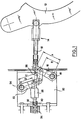
- the mechanical force amplifier comprises an input rod 10 which, in the example illustrated, is pivotally mounted at one end on a brake pedal 12 of a vehicle (not shown).
- the input rod 10 comprises an adjustment means 14 intended to allow the length of the rod 10 to be adjusted when the amplifier is mounted on the vehicle.
- the other end of the input rod 10 is pivotally mounted on one end of a first lever 16 which is pivotally mounted at its other end on a pin 18 fixedly mounted in a fitting 20.
- a second lever 22 is mounted pivotally at one end on a second axis 24 fixedly mounted in the fitting 20.
- the second lever 22 is pivotally connected at its other end to a connecting rod 26 which is also pivotally mounted on the first lever 16.
- the distance between the centers of the pivot points at the ends of the first lever 16 is indicated by the letter A, while the distance between the center of the axis 18 and the center of the pivot point of the connecting rod 26 on the first lever 16 is B.
- the distance between the center of the axis 24 and the center of the pivot point of the link 26 on the second lever 22 is C.
- the force amplifier further comprises an outlet rod 28 pivotally mounted on the second lever 22 at a distance D from the center of the axis 24.
- the outlet rod 28 has a rounded head 30 which is received in a corresponding opening 32 in an actuating piston 34 of a brake emitter (not shown).
- the races of the inlet rod 10, of the connecting rod 26 and of the outlet rod 28 are represented respectively in FIG. 2 by the letters X i , X 2 and X 3 .
- the relationship between X 1 , X 2 and Xs is as follows:
- the dimensions A and C are equal as well as the dimensions B and D.
Landscapes
- Engineering & Computer Science (AREA)
- Physics & Mathematics (AREA)
- Transportation (AREA)
- Mechanical Engineering (AREA)
- General Physics & Mathematics (AREA)
- Automation & Control Theory (AREA)
- Fluid Mechanics (AREA)
- Braking Elements And Transmission Devices (AREA)
- Braking Arrangements (AREA)
Claims (5)
Applications Claiming Priority (2)
| Application Number | Priority Date | Filing Date | Title |
|---|---|---|---|
| FR8612666A FR2603717B1 (fr) | 1986-09-10 | 1986-09-10 | Amplificateur mecanique d'effort, notamment pour systeme de freinage d'un vehicule |
| FR8612666 | 1986-09-10 |
Publications (2)
| Publication Number | Publication Date |
|---|---|
| EP0260168A1 EP0260168A1 (de) | 1988-03-16 |
| EP0260168B1 true EP0260168B1 (de) | 1990-01-10 |
Family
ID=9338829
Family Applications (1)
| Application Number | Title | Priority Date | Filing Date |
|---|---|---|---|
| EP19870401835 Expired - Lifetime EP0260168B1 (de) | 1986-09-10 | 1987-08-07 | Mechanischer Kraftverstärker für Fahrzeugbremssystem |
Country Status (4)
| Country | Link |
|---|---|
| EP (1) | EP0260168B1 (de) |
| DE (1) | DE3761364D1 (de) |
| ES (1) | ES2012405B3 (de) |
| FR (1) | FR2603717B1 (de) |
Families Citing this family (6)
| Publication number | Priority date | Publication date | Assignee | Title |
|---|---|---|---|---|
| US5318275A (en) * | 1992-01-21 | 1994-06-07 | Thetford Corporation | Portable waste holding tank with improved inlet valve assembly |
| RU2178366C2 (ru) * | 2000-04-14 | 2002-01-20 | Ульяновский государственный технический университет | Устройство для управления тормозами транспортного средства |
| RU2179123C1 (ru) * | 2000-12-07 | 2002-02-10 | Открытое акционерное общество "Троллейбусный завод" ("TROLZA") | Привод комбинированной тормозной системы транспортного средства |
| FR2860566B1 (fr) * | 2003-10-06 | 2007-04-13 | Bosch Gmbh Robert | Dispositif amplificateur de course et systeme de commande de freinage automobile comportant un tel dispositif. |
| CN108556822A (zh) * | 2018-01-02 | 2018-09-21 | 北京汽车股份有限公司 | 机械助力式制动系统以及车辆 |
| CN108099882B (zh) * | 2018-01-02 | 2020-06-26 | 北京汽车股份有限公司 | 机械助力式制动系统及具有其的车辆 |
Family Cites Families (4)
| Publication number | Priority date | Publication date | Assignee | Title |
|---|---|---|---|---|
| FR1166904A (fr) * | 1956-02-20 | 1958-11-17 | Bendix Aviat Corp | Tringlerie de commande à rapport d'amplification variable |
| GB819501A (en) * | 1956-10-06 | 1959-09-02 | Fodens Ltd | Improvements relating to brake mechanism for vehicles |
| JPS5951472B2 (ja) * | 1979-11-16 | 1984-12-14 | トヨタ自動車株式会社 | 組立式自動車 |
| US4385528A (en) * | 1980-10-08 | 1983-05-31 | The Bendix Corporation | Brake pedal linkage assembly |
-
1986
- 1986-09-10 FR FR8612666A patent/FR2603717B1/fr not_active Expired - Lifetime
-
1987
- 1987-08-07 ES ES87401835T patent/ES2012405B3/es not_active Expired - Lifetime
- 1987-08-07 EP EP19870401835 patent/EP0260168B1/de not_active Expired - Lifetime
- 1987-08-07 DE DE8787401835T patent/DE3761364D1/de not_active Expired - Lifetime
Also Published As
| Publication number | Publication date |
|---|---|
| FR2603717A1 (fr) | 1988-03-11 |
| FR2603717B1 (fr) | 1992-02-28 |
| EP0260168A1 (de) | 1988-03-16 |
| DE3761364D1 (de) | 1990-02-15 |
| ES2012405B3 (es) | 1990-03-16 |
Similar Documents
| Publication | Publication Date | Title |
|---|---|---|
| US5970817A (en) | Brake operating device | |
| EP0283328B1 (de) | Lastabhängiges Fahrzeugbremsventil | |
| EP0928727A3 (de) | Fahrzeugbremspedalanordnung | |
| US20020088303A1 (en) | Vehicle pedal device capable of adjusting pedal position in longitudinal direction of vehicle | |
| EP0260168B1 (de) | Mechanischer Kraftverstärker für Fahrzeugbremssystem | |
| WO2002055353A3 (en) | Brake pedal assembly with variable ratio | |
| EP0050540A1 (de) | Aufbau einer Bremspedalverbindung | |
| EP1724170A2 (de) | Bremspedal | |
| EP0816205A3 (de) | Lenksäuleneinheit für Fahrzeug | |
| EP0230823B1 (de) | Bremskraftverstärker mit doppelter Reaktionsscheibe | |
| EP0788968A3 (de) | Nachstellvorrichtung für den Anlegehub eines Bremshebels | |
| EP1943145B1 (de) | Befestigungsvorrichtung für einen turbostrahlmotor mit einer strebe zur befestigung an einem flugzeug | |
| EP0967144A3 (de) | Fahrrad-Bremsgerät | |
| US5775173A (en) | Actuating device for a cable line | |
| FR2459744A1 (fr) | Pedale de frein de vehicule a moteur | |
| EP1565367B1 (de) | Verfahren zur einstellung eines bremssystems | |
| EP0978430A3 (de) | Feststellbremsvorrichtung | |
| WO2001096161A3 (de) | Feststellbremse | |
| EP0053528B1 (de) | Bremsdruckregler | |
| GB1580005A (en) | Hand-operable lever assemblies | |
| EP0059139B1 (de) | Servomotor für Bremskraftverstärkung mit reduziertem Betätigungstotgang | |
| EP0192547B1 (de) | Betätigungseinrichtung für Doppelhauptbremszylinder | |
| EP0125978A3 (de) | Einrichtung zur Verriegelung, insbesondere einer Sitzrückenlehnenoberkante an einem Aufbauteil | |
| GB2224337A (en) | Apparatus for selective operation of two valves by one lever, e.g. in backhoe vehicle | |
| EP0770536A3 (de) | Hebelvorrichtung zum Entkuppeln oder Lösen eines Lenkrades von der Lenksäule zur Verstellung |
Legal Events
| Date | Code | Title | Description |
|---|---|---|---|
| PUAI | Public reference made under article 153(3) epc to a published international application that has entered the european phase |
Free format text: ORIGINAL CODE: 0009012 |
|
| 17P | Request for examination filed |
Effective date: 19870825 |
|
| AK | Designated contracting states |
Kind code of ref document: A1 Designated state(s): DE ES GB IT |
|
| 17Q | First examination report despatched |
Effective date: 19881229 |
|
| GRAA | (expected) grant |
Free format text: ORIGINAL CODE: 0009210 |
|
| AK | Designated contracting states |
Kind code of ref document: B1 Designated state(s): DE ES GB IT |
|
| GBT | Gb: translation of ep patent filed (gb section 77(6)(a)/1977) | ||
| REF | Corresponds to: |
Ref document number: 3761364 Country of ref document: DE Date of ref document: 19900215 |
|
| ITF | It: translation for a ep patent filed | ||
| PLBE | No opposition filed within time limit |
Free format text: ORIGINAL CODE: 0009261 |
|
| STAA | Information on the status of an ep patent application or granted ep patent |
Free format text: STATUS: NO OPPOSITION FILED WITHIN TIME LIMIT |
|
| 26N | No opposition filed | ||
| ITTA | It: last paid annual fee | ||
| PGFP | Annual fee paid to national office [announced via postgrant information from national office to epo] |
Ref country code: GB Payment date: 19960729 Year of fee payment: 10 |
|
| PGFP | Annual fee paid to national office [announced via postgrant information from national office to epo] |
Ref country code: DE Payment date: 19960816 Year of fee payment: 10 |
|
| PGFP | Annual fee paid to national office [announced via postgrant information from national office to epo] |
Ref country code: ES Payment date: 19960830 Year of fee payment: 10 |
|
| PG25 | Lapsed in a contracting state [announced via postgrant information from national office to epo] |
Ref country code: GB Free format text: LAPSE BECAUSE OF NON-PAYMENT OF DUE FEES Effective date: 19970807 |
|
| PG25 | Lapsed in a contracting state [announced via postgrant information from national office to epo] |
Ref country code: ES Free format text: LAPSE BECAUSE OF THE APPLICANT RENOUNCES Effective date: 19970808 |
|
| GBPC | Gb: european patent ceased through non-payment of renewal fee |
Effective date: 19970807 |
|
| PG25 | Lapsed in a contracting state [announced via postgrant information from national office to epo] |
Ref country code: DE Free format text: LAPSE BECAUSE OF NON-PAYMENT OF DUE FEES Effective date: 19980501 |
|
| REG | Reference to a national code |
Ref country code: ES Ref legal event code: FD2A Effective date: 20001009 |
|
| PG25 | Lapsed in a contracting state [announced via postgrant information from national office to epo] |
Ref country code: IT Free format text: LAPSE BECAUSE OF NON-PAYMENT OF DUE FEES;WARNING: LAPSES OF ITALIAN PATENTS WITH EFFECTIVE DATE BEFORE 2007 MAY HAVE OCCURRED AT ANY TIME BEFORE 2007. THE CORRECT EFFECTIVE DATE MAY BE DIFFERENT FROM THE ONE RECORDED. Effective date: 20050807 |