EP0260364B1 - Réseau de commutation de paquets avec capacité de diffusion - Google Patents
Réseau de commutation de paquets avec capacité de diffusion Download PDFInfo
- Publication number
- EP0260364B1 EP0260364B1 EP86401052A EP86401052A EP0260364B1 EP 0260364 B1 EP0260364 B1 EP 0260364B1 EP 86401052 A EP86401052 A EP 86401052A EP 86401052 A EP86401052 A EP 86401052A EP 0260364 B1 EP0260364 B1 EP 0260364B1
- Authority
- EP
- European Patent Office
- Prior art keywords
- packet
- network
- routing
- packets
- copy
- Prior art date
- Legal status (The legal status is an assumption and is not a legal conclusion. Google has not performed a legal analysis and makes no representation as to the accuracy of the status listed.)
- Expired - Lifetime
Links
- 238000009826 distribution Methods 0.000 claims abstract description 42
- 238000004891 communication Methods 0.000 claims abstract description 4
- 238000013519 translation Methods 0.000 claims description 49
- 230000015654 memory Effects 0.000 claims description 33
- 238000000034 method Methods 0.000 claims description 15
- 230000002457 bidirectional effect Effects 0.000 claims description 8
- 230000008569 process Effects 0.000 claims description 7
- 230000003362 replicative effect Effects 0.000 claims 5
- 230000014616 translation Effects 0.000 description 45
- 239000000835 fiber Substances 0.000 description 37
- 239000000872 buffer Substances 0.000 description 36
- 239000004744 fabric Substances 0.000 description 29
- 230000006870 function Effects 0.000 description 11
- 238000012360 testing method Methods 0.000 description 11
- 230000010076 replication Effects 0.000 description 8
- 238000011144 upstream manufacturing Methods 0.000 description 7
- 230000005540 biological transmission Effects 0.000 description 4
- 238000013459 approach Methods 0.000 description 3
- 230000008901 benefit Effects 0.000 description 3
- 230000003287 optical effect Effects 0.000 description 3
- 230000004044 response Effects 0.000 description 3
- FZRPRRCXGGAZEW-HSZRJFAPSA-N (2r)-n-(6-aminohexyl)-1-tridecanoylpiperidine-2-carboxamide Chemical compound CCCCCCCCCCCCC(=O)N1CCCC[C@@H]1C(=O)NCCCCCCN FZRPRRCXGGAZEW-HSZRJFAPSA-N 0.000 description 2
- 230000008859 change Effects 0.000 description 2
- 238000005304 joining Methods 0.000 description 2
- 239000013307 optical fiber Substances 0.000 description 2
- FDWIKIIKBRJSHK-UHFFFAOYSA-N 2-(2-methyl-4-oxochromen-5-yl)acetic acid Chemical compound C1=CC=C2OC(C)=CC(=O)C2=C1CC(O)=O FDWIKIIKBRJSHK-UHFFFAOYSA-N 0.000 description 1
- 240000003537 Ficus benghalensis Species 0.000 description 1
- 238000003491 array Methods 0.000 description 1
- 239000013256 coordination polymer Substances 0.000 description 1
- 238000012937 correction Methods 0.000 description 1
- 230000001934 delay Effects 0.000 description 1
- 238000013461 design Methods 0.000 description 1
- 239000000284 extract Substances 0.000 description 1
- 239000003292 glue Substances 0.000 description 1
- 230000003993 interaction Effects 0.000 description 1
- 230000002452 interceptive effect Effects 0.000 description 1
- 238000004519 manufacturing process Methods 0.000 description 1
- 230000001575 pathological effect Effects 0.000 description 1
- 238000012545 processing Methods 0.000 description 1
- 230000008672 reprogramming Effects 0.000 description 1
- 230000003068 static effect Effects 0.000 description 1
- 230000001360 synchronised effect Effects 0.000 description 1
- 238000012546 transfer Methods 0.000 description 1
Images


Classifications
-
- H—ELECTRICITY
- H04—ELECTRIC COMMUNICATION TECHNIQUE
- H04L—TRANSMISSION OF DIGITAL INFORMATION, e.g. TELEGRAPHIC COMMUNICATION
- H04L49/00—Packet switching elements
- H04L49/50—Overload detection or protection within a single switching element
- H04L49/505—Corrective measures
-
- H—ELECTRICITY
- H04—ELECTRIC COMMUNICATION TECHNIQUE
- H04L—TRANSMISSION OF DIGITAL INFORMATION, e.g. TELEGRAPHIC COMMUNICATION
- H04L12/00—Data switching networks
- H04L12/02—Details
- H04L12/16—Arrangements for providing special services to substations
- H04L12/18—Arrangements for providing special services to substations for broadcast or conference, e.g. multicast
- H04L12/1854—Arrangements for providing special services to substations for broadcast or conference, e.g. multicast with non-centralised forwarding system, e.g. chaincast
-
- H—ELECTRICITY
- H04—ELECTRIC COMMUNICATION TECHNIQUE
- H04L—TRANSMISSION OF DIGITAL INFORMATION, e.g. TELEGRAPHIC COMMUNICATION
- H04L49/00—Packet switching elements
- H04L49/10—Packet switching elements characterised by the switching fabric construction
- H04L49/104—Asynchronous transfer mode [ATM] switching fabrics
- H04L49/105—ATM switching elements
- H04L49/106—ATM switching elements using space switching, e.g. crossbar or matrix
-
- H—ELECTRICITY
- H04—ELECTRIC COMMUNICATION TECHNIQUE
- H04L—TRANSMISSION OF DIGITAL INFORMATION, e.g. TELEGRAPHIC COMMUNICATION
- H04L49/00—Packet switching elements
- H04L49/15—Interconnection of switching modules
- H04L49/1553—Interconnection of ATM switching modules, e.g. ATM switching fabrics
- H04L49/1561—Distribute and route fabrics, e.g. Batcher-Banyan
-
- H—ELECTRICITY
- H04—ELECTRIC COMMUNICATION TECHNIQUE
- H04L—TRANSMISSION OF DIGITAL INFORMATION, e.g. TELEGRAPHIC COMMUNICATION
- H04L49/00—Packet switching elements
- H04L49/20—Support for services
- H04L49/201—Multicast operation; Broadcast operation
-
- H—ELECTRICITY
- H04—ELECTRIC COMMUNICATION TECHNIQUE
- H04L—TRANSMISSION OF DIGITAL INFORMATION, e.g. TELEGRAPHIC COMMUNICATION
- H04L49/00—Packet switching elements
- H04L49/20—Support for services
- H04L49/201—Multicast operation; Broadcast operation
- H04L49/203—ATM switching fabrics with multicast or broadcast capabilities
-
- H—ELECTRICITY
- H04—ELECTRIC COMMUNICATION TECHNIQUE
- H04L—TRANSMISSION OF DIGITAL INFORMATION, e.g. TELEGRAPHIC COMMUNICATION
- H04L12/00—Data switching networks
- H04L12/54—Store-and-forward switching systems
- H04L12/56—Packet switching systems
- H04L12/5601—Transfer mode dependent, e.g. ATM
- H04L2012/5638—Services, e.g. multimedia, GOS, QOS
- H04L2012/5646—Cell characteristics, e.g. loss, delay, jitter, sequence integrity
- H04L2012/5652—Cell construction, e.g. including header, packetisation, depacketisation, assembly, reassembly
-
- H—ELECTRICITY
- H04—ELECTRIC COMMUNICATION TECHNIQUE
- H04L—TRANSMISSION OF DIGITAL INFORMATION, e.g. TELEGRAPHIC COMMUNICATION
- H04L49/00—Packet switching elements
- H04L49/15—Interconnection of switching modules
- H04L49/1507—Distribute and route fabrics, e.g. sorting-routing or Batcher-Banyan
-
- H—ELECTRICITY
- H04—ELECTRIC COMMUNICATION TECHNIQUE
- H04L—TRANSMISSION OF DIGITAL INFORMATION, e.g. TELEGRAPHIC COMMUNICATION
- H04L49/00—Packet switching elements
- H04L49/25—Routing or path finding in a switch fabric
-
- H—ELECTRICITY
- H04—ELECTRIC COMMUNICATION TECHNIQUE
- H04L—TRANSMISSION OF DIGITAL INFORMATION, e.g. TELEGRAPHIC COMMUNICATION
- H04L49/00—Packet switching elements
- H04L49/25—Routing or path finding in a switch fabric
- H04L49/253—Routing or path finding in a switch fabric using establishment or release of connections between ports
- H04L49/254—Centralised controller, i.e. arbitration or scheduling
-
- H—ELECTRICITY
- H04—ELECTRIC COMMUNICATION TECHNIQUE
- H04L—TRANSMISSION OF DIGITAL INFORMATION, e.g. TELEGRAPHIC COMMUNICATION
- H04L49/00—Packet switching elements
- H04L49/30—Peripheral units, e.g. input or output ports
-
- H—ELECTRICITY
- H04—ELECTRIC COMMUNICATION TECHNIQUE
- H04L—TRANSMISSION OF DIGITAL INFORMATION, e.g. TELEGRAPHIC COMMUNICATION
- H04L49/00—Packet switching elements
- H04L49/35—Switches specially adapted for specific applications
- H04L49/356—Switches specially adapted for specific applications for storage area networks
- H04L49/357—Fibre channel switches
-
- H—ELECTRICITY
- H04—ELECTRIC COMMUNICATION TECHNIQUE
- H04L—TRANSMISSION OF DIGITAL INFORMATION, e.g. TELEGRAPHIC COMMUNICATION
- H04L49/00—Packet switching elements
- H04L49/55—Prevention, detection or correction of errors
- H04L49/557—Error correction, e.g. fault recovery or fault tolerance
Definitions
- the present invention relates to a high performance packet switching network having a broadcast capability. More particularly, it relates to a packet switch for use in such a network, and to methods for copying a data packet and distributing the copy of the data packet and for controlling the passage of data packets through a copy network.
- a packet switching network generally comprises an array of packet switches, which switches are generally connected by one or more high bit rate data links. Virtual circuits passing through a plurality of packet switches are set up in the network to provide point-to-point connections between pairs of user stations that wish to exchange information.
- An example of a packet switching network is disclosed in Turner "A Fast Packet Switching Network", U.S. Patent No. 4,494,230. While prior art packet switching networks such as that disclosed in U.S. Patent 4,494,230 are generally suitable for providing point-to-point connections between pairs of user stations, such prior art packet switching networks are not capable of operating efficiently in the broadcast mode. Thus, they cannot provide a variety of commercial services including television distribution and conferencing.
- the present invention is a high performance packet switching network having point-to-point as well as broadcast capability. This enables a wide range of commercial services including television distribution and conferencing.
- the basic switching capability of the inventive network is provided by a packet switching module.
- the switching modules of the present invention are designed to be modular so that they can be interconnected to form packet switches which, in turn, may be interconnected to form the packet switching network.
- a means for interconnecting the switching modules is provided so that the number of interconnected switching modules may be varied with a minimum of recabling.
- Each of the switch modules illustratively comprises a copy network, a set of broadcast and group translators, a distribution network and a routing network. Broadcast packets are replicated in the copy network. Each copy of a broadcast packet that leaves the copy network is provided with a destination address by one of the broadcast and group translators. The distribution and routing network then route the packet copies to their destinations. A method for adding or deleting destinations from a given broadcast channel is provided.
- the copy, distribution and routing networks each comprise an array of nodes arranged in stages.
- An algorithm is provided which enables each node in the copy network to decide whether or not to replicate a given broadcast packet. Packets belonging to point-to-point connections pass through the copy network unchanged.
- individual data links may be grouped together to form a link having a bit rate higher than that of any individual data link in the group.
- a method and apparatus for grouping individual data links and for distributing packets among the individual links in the group is discussed below.
- the architecture of a packet switching network is illustrated in figure 1.
- the network 10 comprises an array of packet switches 12, 14, 16, 18, 20 which are illustratively interconnected by one or more high performance data links 22, 24, 26, 28, 30.
- the data links are bidirectional fiber optic data links.
- the fiber optic links have a higher bandwidth capability than conventional non-optical electronic links.
- the packet switches 18 and 16 are connected by a single fiber optic link while the switches 14 and 16 are connected by three fiber optic links.
- Access to the network is provided by network interfaces 40, 42, 44, 46, 48, 50 which are connected to the packet switches 12, 14, 16, 18, 20 by way of fiber optic links.
- the network interfaces serve to interface other networks such as telephone network 50, data network 52 and customer premises equipment 54 with the packet switching network 10.
- the network 10 of figure 1 provides two main communication services.
- a user may set up a two- way point-to-point channel with any other user.
- the point-to-point channel is in the form of a virtual circuit which passes through any number of the packet switches 12, 14, 16, 18, 20.
- Any user may also set up a broadcast service that other users are connected to. The method by which such broadcast channels are handled by the network is discussed below.
- the packet switching network 10 can be used to provide voice, data and video communication on a large scale.
- An important feature of this network 10 is its broadcast capability which makes it suitable for a wide range of applications including television distribution and conferencing.
- the basic packet switching capability of the packet switches 12, 14, 16, 18, 20 comprising the network 10 is provided by a high performance switch module.
- Groups of switch modules may be interconnected to form the packet switches 12, 14, 16, 18, 20 and the network interfaces 40, 42, 44, 46, 48, 50 of figure 1.
- Interconnection circuitry discussed in greater detail below, is provided so that the number of interconnected switch modules may be easily changed with a minimum of recabling.
- the switch module 200 illustratively terminates up to N bidirectional fiber optic links 202-1 ... 202-N. Typically, N is on the order of 63 and each fiber optic link operates at to 100 Megabits/sec.
- the switch fabric 204 is the heart of the switch module 200.
- the high bit rate optical fiber links 202-1 ... 202-N interface with the switch fabric 204 by means of packet processors 206-1 ... 206-N.
- a packet being transmitted over a point-to-point connection enters the switch fabric 204 from one of the fiber optic links via one of the packet processors and leaves the switch fabric through another of the packet processors and associated fiber optic link.
- a broadcast packet enters the switch fabric through one packet processor, is replicated in the switch fabric and leaves via a number of packet processors and associated fiber optic links.
- the packet processors perform link level protocol functions including the determination of how each packet is routed through the switch fabric. Routing information is stored in memories contained within each packet processor.
- the connection processor 208 is responsible for establishing connections including both point-to-point connections and broadcast connections. To do this, the connection processor 208 exchanges control packets with connection processors in neighboring switch modules and controls the routing actions of the packet processors and the switch fabric by writing routing information into memory tables contained therein.
- the connection processor 208 is a stored program machine such as a microprocessor.
- Figure 3 shows the format of a data transfer packet that is being transmitted between a pair of switch modules within a single packet switch or network interface or that is being transmitted between switching modules in adjacent packet switches and/or network interfaces.
- these packets may be 600 bytes long and are separated by a flag pattern (F).
- FTYP Frame Type
- the Frame Type (FTYP) field is used to distinguish among several types of packets at the link protocol level including, for example, outgoing test packets, incoming test packets, and a packet belonging to a point-to-point or broadcast connection. Test packets are used to test the operation of a fiber optic link or a switch fabric. (See, for example, Turner, U.S. Patent No. 4,486,877).
- the packet type field (PTYP) identifies each packet as either a data packet or a control packet and contains a congestion control sub-field (not shown) used to inform the network interface and customers of internal network congestion.
- the logical channel number field (LCN) indicates which point-to-point or broadcast connection a packet belongs to.
- the packet also includes an information field I which illustratively is 594 bytes long and contains the user or control information to be transmitted.
- a frame check field (FC) at the end of the packet is used for error correction.
- FIG. 4 shows the format of the packets after they enter a switch module. Flags are removed and new header information is added to the packet, which enables the packet to be routed through the switch module. Illustratively, each packet is 606 bytes long after it enters a switch module.
- the new header information includes a routing field (RF) which determines the routing of the packet through the switch module.
- the routing field (RF) comprises three subfields. The first subfield is a routing control field (RC) which determines the type of routing a packet will receive in the switch module. The following are the types of routing a packet may undergo in a switch module :
- GN group number
- GN group number
- the interpretation of the next two sub-fields depends on the RC field.
- the second sub-field is the number of copies (NC) to be produced in the switch module, i.e., the number of outgoing fiber optic links which require a copy of the packet and the third field is a Broadcast Channel Number (BCN) which is used to distinguish between different broadcast channels within the switch module.
- N number of copies
- BCN Broadcast Channel Number
- the second field is interpreted as the outgoing fiber optic link number (LN) or outgoing group number (GN) depending on whether or not there is group translation and the third field is interpreted as an outgoing logical channel number (LCNo), i.e. the logical channel number the packet will have when it leaves the switch module.
- LN fiber optic link number
- GN outgoing group number
- the third field is interpreted as an outgoing logical channel number (LCNo), i.e. the logical channel number the packet will have when it leaves the switch module.
- the control field identifies different types of packets within the switch module including various sorts of control packets.
- the source field identifies the packet processor of origin within the switch module.
- Logical channel translation is the process used to determine how to route a packet belonging to a particular broadcast or point-to-point connection through a switch module.
- Each packet processor contains a logical channel translation table (LCXT) which is used for this purpose.
- LCXT logical channel translation table
- the entries in the LCXTs are maintained by the connection processor (see fig. 2) which typically writes a new LCXT entry when a new connection is established.
- the structure of one of the packet processors 206-1 ... N is shown in figure 5.
- the packet processor 206 of figure 5 serves to interface one of the bidirectional fiber optic links 202-1 ... 202-N with the switch fabric 204 of figure 2.
- the packet processor 206 of figure 5 comprises four packet buffers 220, 222, 224, 226.
- the receive buffer 220 is used for packets arriving on the fiber optic link 202 and waiting to pass through the switch fabric.
- the transmit buffer 222 buffers packets arriving from the switch fabric 204 that are waiting to be sent out on the fiber optic link 202.
- the link test buffer 224 and switch test buffer 226 provide paths for test packets used to verify the operation of the fiber optic link 220 and switch fabric 204, respectively.
- the logical channel translation table LCXT 228 is a memory which stores packet routing information as discussed above.
- the receive circuit 230 converts the incoming serial optical signal transmitted over the optical fiber link 202 to an electrical signal in an eight bit parallel format, synchronizes the signal to the local clock, routes test packets to the link test buffer 224 and other packets to the receive buffer 220.
- the eight bit parallel signal format is the signal format used by the switch fabric.
- the output circuit 232 takes packets from the receive buffer 220 and uses the LCN contained therein to address the logical channel translation table memory (LCXT) 228.
- the RC, NC/LN/GN, and BCN/LCNo, fields are read from the logical channel translation table memory (LCXT) 228 and written into the packet header as shown in figure 4.
- the SOURCE field is filled in by the packet processor 202 based on the packet processor identification number.
- the CONTROL field is calculated by the output circuit based on information contained in the packet. The packet is then sent on to the switch fabric 204.
- the input circuit 234 receives packets from the switch fabric 204 and sends them to the transmit buffer 222.
- the input circuit removes the RC, NC/LN/GN and BCN/LCNo sub-fields which served to route the packet through the switch fabric while moving the LCNo number to the position occupied by the LCN.
- the input circuit 234 also routes switch fabric test packets through the switch test buffer 226 to the output circuit 232.
- the LCXT of the packet processor needs to be updated. This is accomplished by having the connection processor 208 form an LCXT update packet, which is transmitted from the connection processor through the switch fabric 204 to the input circuit 234. The input circuit 234 then writes appropriate information from the LCXT update packet in the LCXT memory.
- the transmit circuit 236 takes packets from the transmit buffer 222, adds the flag field (F) and converts the 8 bit parallel electrical signal into a serial optical signal for transmission over the fiber optic link 202.
- FIG. 6 A more detailed view of the switch module 200 of figure 2 is shown in figure 6.
- packet processors 206-1 ... 206-N Connected to the switch fabric 204, are packet processors 206-1 ... 206-N and connection processor 208.
- connection processor and the packet processor are each shown twice, once at the input or left hand side of the switch fabric 204 and one at the output or right hand side of the switch fabric 204. In reality, however, the switch fabric has a closed geometry and there is only one set of packet processors and one connection processor).
- the switch fabric 204 contains four major components, a copy network (CN) 300, a set of Broadcast and Group Translators BGTo ...BGT N , a distribution network (DN) 400, and a routing network 500.
- the copy network 300, the distribution network (DN) 400 and the routing network (RN) 500 each comprise arrays of switching nodes.
- each of the nodes has two inputs and two outputs.
- each of the switching nodes may have four input and four outputs.
- the switching nodes are grouped in stages. Data packets are synchronously transmitted downstream from one stage to the next. Grant signals propagate upstream to inform upstream nodes whether or not downstream nodes in adjacent stages are able to receive data packets.
- the switch fabric 204 runs at a rate of 25 Megabits/sec. and has eight bit wide internal data paths. This gives an effective bit rate of 200 Megabits/sec on the internal data paths, roughly twice the speed of the fiber optic links which operate at 100 Megabits/sec. An occupancy of 80% on the fiber optic links translates to a 40% occupancy on the internal data paths of the switch fabric 204, which keeps contention and delay low in the switch fabric.
- the purpose of the copy network 300 is to copy broadcast packets. When a broadcast packet having k destinations passes through the copy network 300, it is replicated so that k copies of that packet emerge from the copy network. Point-to-point packets pass through the copy network 300 without change.
- the Broadcast and Group Translators BGTo ... BGT perform two translation functions. First, for each arriving broadcast packet, they determine the proper outgoing link number (LN) or group number (GN) based on the number of copies (NC) and Broadcast Channel Number (BCN) fields in the broadcast packet. The group number (GN), if any, is then translated to a link number (LN). Group translation also takes place for point-to-point packets having group numbers (GN). The BGT's do nothing to point-to-point packets already having link numbers (LN) and not requiring group translation.
- LN Link Number
- GN Link Number
- the group number (GN) is used to allow individual fiber optic links which join the same pair of switch modules to be grouped together and treated as one large link. This allows the system to provided connections that have a larger bandwidth than a single link. Consequently, the bandwidth of the fiber optic links does not limit the size of connections the system can provide.
- group translators within the BGT's translate group numbers to link numbers so as to distribute traffic evenly over all links in a group. More particularly, a group number (GN) is successively translated to the link number of each link in the group to achieve the uniform traffic distribution.
- the group translation function is described in greater detail below.
- each broadcast or point-to-point packet leaving the BGT's has a link number (LN) which is essentially the address of the appropriate outgoing packet processor.
- LN link number
- the link number (LN) is added to the packet header from the LCXT memory in the incoming packet processor and the BGT does nothing.
- the link number (LN) is provided by the BGT as a result of translations of the group number (GN).
- the link number LN is provided by the BGT as a result of translation of the broadcast channel number (BCN) possibly followed by group translation of a group number (GN).
- the routing network 500 routes the packets to the appropriate outgoing packet processors based on the aforementioned link number (LN) which is essentially an address of an outgoing packet processor and fiber optic link.
- the distribution network 400 is provided to prevent internal congestion within the routing network 500.
- the operation of the switch fabric 204 is synchronous.
- the timing is summarized in figure 7 for the case where each switch packet is 606 bytes long and the copy routing and distribution networks are 64 x 64 networks comprising 6 stages of 2 x 2 switching nodes each.
- packets enter the copy network 300 from the packet processors. 96 clock cycles later they enter the BGT's. 64 cycles later they enter the distribution network 400. 96 cycles later they enter the routing network and 96 cycles after that the packets begin to enter the appropriate outgoing packet processors, 400 clock cycles after the start of the packet cycle, grant signals are presented to the last stage of the routing network 500. 48 cycles later grant signals are presented at the last stage of the distribution network 400. After an additional 48 cycles grant signals are presented at the BGT outputs and 4 cycles later grant signals are presented to the last stage of the copy network.
- a new packet cycle starts with an input to the copy network 300 at clock cycle number 608.
- the routing network is discussed first because it is the easiest network to understand and because it provides a basis for understanding the distribution and copy networks.
- a 16 x 16 version of the routing network 500 is illustrated.
- the 16 x 16 version of the routing network comprises four stages 502, 504, 506, 508, each stage comprising eight nodes.
- Each of the nodes for example the node 510, has two inputs 511, 513 and two outputs 515, 517.
- a packet entering the node 510 on either input will be routed to the upper or lower output, depending on whether the appropriate address bit is a zero (upper output) or one (lower output).
- the routing network 500 is bit addressable, i.e. the route a packet takes through the network is determined by successive bits of its destination address.
- Figure 8 shows two different paths 520, 530 to the destination (e.g. packet processor) having address 1011.
- the packets in paths 520, 530 are routed to the lower output port of the appropriate node as the first bit of the destination address is a one.
- the packets are routed to the upper output port of the appropriate node as the second destination address bit is zero.
- the packets are routed to the lower output ports as the third and fourth address bits are both one.
- This self-routing property is shared by a variety of networks including delta, shuffle exchange, and banyan networks. Such self-routing bit addressable networks are disclosed in U.S. Patent 4,490,234.
- binary routing networks such as the binary routing network illustrated in figure 8 are congested in the presence of certain traffic patterns.
- figure 9 shows a traffic pattern corresponding to several communities of interest.
- all traffic entering the first four inputs is destined for the first four outputs and all traffic entering the second four inputs is destined for the second four outputs.
- this traffic pattern only one fourth of the links joining the second and third stages of the network in figure 9 are carrying traffic. Thus, if the inputs are heavily loaded, those links carrying traffic between the second and third stages will be hopelessly overloaded and traffic will back up.
- the distribution network 400 solves this problem by evenly distributing packets it receives across all its outputs.
- the distribution network 400 has an internal structure similar to that of the routing network 500. However, the nodes of the distribution network ignore the destination addresses on packets and route them alternately to each of their output ports. If one or both ports is unavailable, the first port to become available is used. This approach breaks up any communities of interest and makes the combination of the distribution network 400 and routing network 500 robust in the face of pathological traffic patterns.
- the copy network 300 is illustrated.
- the function of the copy network is to make copies of broadcast packets as they pass through.
- the packet 302 entering at left is a broadcast packet as indicated by the letter B in the routing control sub-field.
- the number of copies (NC) field is 7 and the broadcast channel number (BCN) is 36.
- the copy network 300 must make seven copies of the packet 302 which belongs to broadcast channel number 36.
- the copy network 300 comprises an array of nodes (e.g. node 304, 306) having two input ports and two output ports.
- the array of nodes 300 is divided into stages which are labeled 1, 2, 3, 4, from right to left for reasons which will become clear.
- the nodes of the copy network differ from the nodes of the routing and distribution network only in that a different algorithm is used to determine which output port a packet utilizes. In some cases a packet will leave via one output port. In other cases, the packet will be replicated by the node and leave the node via both output ports.
- BCN and NC are the broadcast channel number of copies fields from the packet as indicated above.
- sn is the stage number of the node where stages are numbered from right to left starting with I.
- Each BGT contains a broadcast translation table (BTT) used for this purpose.
- the BTT is indexed by the BCN of the incoming broadcast packet.
- the selected entry is the BTT contains the appropriate group number (GN) or link number (LN) and outgoing logical channel number (LCNo) for the packet, which numbers are written into the appropriate fields of the packet header.
- the link number (LN) is used to route the packet through the routing network to the appropriate outgoing packet processor and fiber-optic link.
- a further translation step is required to obtain the link number (LN).
- the LCNo is used to read the logical channel translation table (LCXT) in the next switch module traversed by the packet.
- Packets 308 and 310 are copies of packet 302. The only difference is that the NC field of each packet has been reduced to 1 as a result of the decision making algorithm used by the nodes in the copy network.
- the BCN of packets 308 and 310 is 36. Packet 308 indexes BTTg, while packet 310 indexes BTT 15 , both of which are part of the BGT's for the appropriate outputs of the copy network. Even though both packets have the same BCN, the packets 308 and 310 acquire different group or link numbers (GN or LN) and different outgoing logical channel numbers (LCNo).
- an "L” is written into the routing control field (RC) of packet 308 to designate that after broadcast translation the packet is now a point-to-point packet not requiring group translation.
- Packet 308 acquires a link number LN of 3 and LCNo of 27.
- a "G” is written into the routing control field (RC) of packet 310, indicating that after broadcast translation the packet 308 is now a point-to-point packet requiring group translation.
- Packet 310 acquires a GN of 24 and an LCNo of 41.
- the group number 24 means that the packet 310 will be routed to one link in a group of links designated by number 24.
- the group number 24 is translated into the link number of one of the links in the group in a manner so that packets are evenly distributed to all of the links in the group.
- the packets 308, 310 are routed to different outgoing packet processors by the routing network 500.
- Output ports of the copy network 300 which require the same BTT entry for a given BCN have the same broadcast copy index or bci.
- the bci for a particular output port is a function of the NC field and the low order bit of the BCN.
- bci k NC, BCN
- the bci k (NC, BCN) function is chosen so that output ports with the same bci will have the same BTT entry for identical BCN numbers.
- the aforementioned algorithm may be used as follows to calculate bci 3 (7, 36).
- the binary representation of 3 is 0011.
- the initial value of s is 0 and the initial value of x is 7.
- the third interaction of the for-loop i 1.
- the algorithm may also be used to calculate bci 1 (7,36).
- the binary representation of 11 is 1011.
- the initial value of s is zero and the initial value of x is 7.
- During the third iteration of the for-loop i 1.
- each of the BGT's shown in figure 6 also includes a memory table which stores values of bci k (NC, BCN) for each possible value of NC, BCN.
- This table is static and different for each of the BGT's (i.e. is different for each output port).
- Each table of bci values is used to control the writing of information into the associated BTT to insure that BTT's for ports with the same bci value as a function of NC and BCN have identical entries for that particular value of BCN.
- the connection processor wishes to update the BTT's for a particular broadcast channel, it sends a control packet of the form shown in figure 11.
- the B indicates that the packet of figure 11 is a broadcast packet.
- the copy network replicates the packet so that each BGT in the switch module receives a copy.
- the BGT k receives a copy, it extracts BCN from the routing field (RF) of the control packet of figure 11 and NC' from the information field of the packet of figure 11.
- RF h is copied from the packet into BTT k (BCN), wherein RF h includes the RC, GN/LN and LCN fields included in the broadcast translation table (BTT) as discussed above.
- BCN BTT k
- NC' is included in the information field of the broadcast packet.
- the broadcast update packet of figure 11 originates in the connection processor of the switch module. It is replicated in the copy network and it goes to each of the BGTs.
- the NC value in the outgoing field of each copy of the broadcast update packet is 1 when the copy leaves the copy network.
- the value NC' is placed in the information field of the broadcast update packet for purposes of indexing the table of bci values).
- connection processor 208 of the switch module 200 keeps a copy of the BGT update control packet in its memory. To add a new destination, it increments the NC' field, adds a new RF to the end of the packet and sends it into the copy network for replication and transmission to the BGT's. To remove a broadcast destination, the CP decrements the NC' field and removes the RF corresponding to the deleted destination from the BTT update packet before sending it out. Typically, if the RF field removed is not the last one in the packet, then the last one is copied to the position of the removed RF. That is, if we want to eliminate RF for i ⁇ NC' - 1, we copy RF N c'-1 to the position formerly occupied by RF i .
- Each for the BGT's may contain an additional memory table known as the Group Translation Table (GTT).
- GTT Group Translation Table
- the purpose of group translation is to allow individual fiber-optic links which join the same pair of switch modules to be grouped together and treated as one large link. This allows the system to provide connections that have a larger bandwidth than a single link. Consequently, the bandwidth of the individual fiber optic links does not limit the size of connections the system can provide.
- Traffic for a link group is evenly distributed over all this links. This allows dynamic load distribution across a set of links permitting higher utilization.
- GN group number
- GTT group translation table
- link groups are that the logical channel translation tables (LCXTs) (memory 228, figure 5) for all links in a group are identical. Consequently, for every new connection, the connection processor updates the LCXT's for all links in the group. This can be easily handled by sending a broadcast LCXT update packet.
- LCXTs logical channel translation tables
- each BGT contains three main memories, the Broadcast Translation Table (BTT) for converting the broadcast channel number (BCN) in broadcast to link or group numbers, the BCIT or broadcast copy index table for controlling the writing of information into the association BTT and for updating the BTT when a broadcast destination is added or deleted, and a group translation table (GTT) for translating group numbers to link numbers.
- BTT Broadcast Translation Table
- GTT group translation table
- FIG. 13(a) shows a packet 80 arriving on fiber-optic link number 10 and entering packet processor PPio.
- the packet 80 has a logical channel number (LCN) of 6.
- the packet processor PP1 uses the LCN value to index the LCXT contained in the PP1 to retrieve packet routing information stored therein.
- the retrieved routing information is placed in the routing field of the packet 82 as it leaves PP,o.
- the routing field of the packet indicates a broadcast packet (B) with a Number-of-copies field (NC) of 5 and a Broadcast Channel Number (BCN) of 9.
- the packet enters the copy network 300 and is replicated so that five copies emerge from the copy network 300.
- the packet 82 uses the upper input of node 360 of the copy network 300 and is routed to the lower output of node 360 without replication. Replication takes place at nodes 362, 364, 368 and 370 of the copy network, while a packet passes through node 366 without replication. Whether or not replication takes place at a given node in the copy network is decided in accordance with the copy network routing algorithm described in section 9 above.
- the copy labelled 84 arrives at BGT 1 3 . Note that packet 84 has a 1 in its NC field as a result of repeated application of the copy network routing algorithm disclosed in section 9 above.
- the packet 86 requires group translation (indicated by the G) and is destined for link group 7.
- the outgoing logical channel number (LCNo) is 15.
- the selected link is number 11.
- Packet 88 shows the new routing field after the group translation is complete. The packet is destined for link number 11 and has an outgoing logical channel number (LCNo) of 15.
- LCNo logical channel number
- Packet 88 then enters the distribution network 400 of figure 13(b).
- the distribution network makes arbitrary routing decisions.
- packet 88 passes through nodes 460, 462, 464, and 466.
- it takes the lower output port of node 560, the upper output port of node 562, the lower output port of node 564 and the lower output port of node 566. This brings packet 88 to the outgoing packet processor PP 11 .
- LCNo logical channel number
- the packet that emerges from PP 11 has 15 in its LCN field.
- Each node in each of the copy, distribution and routing networks 300, 400, 500 has the inputs and outputs shown in figure 14.
- the upstream data signals (udo, udi) carry data from nodes in the previous stage.
- the downstream data signals (dd(0), dd(1)) carry data to nodes in the following stage.
- the downstream grant signals (dg(0), dg(1)) inform the node if its neighbors in the following stage are prepared to receive new packets.
- the upstream grant signals (ugo, ugi) inform the neighbors in the previous stage if the node of figure 14 is prepared to receive new packets.
- the data signals are eight bits wide and the grant signals are one bit wide.
- a packet coming in on one of the inputs udo, ud 1 is routed to the upper (dd(0)) or lower (dd(1)) output depending on an address bit in the packet.
- incoming packets are routed to the upper or lower outputs on an essentially random basis.
- an incoming packet is either replicated or randomly routed to one or the other output, the decision being made using the copy network routing algorithm discussed in section 9 above.
- the NC number in each packet copy is changed in accordance with the copy network routing algorithm.
- FIG. 15 gives a more detailed picture of a switch node 530 for the Routing Network.
- the node 530 comprises two Input Circuits (ICo, IC1) 532 and 534 and a Node Control Circuit 536.
- the IC 0 532 contains an IC Control circuit 538 and a Packet Buffer 540 capable of storing two packets. It also contains two shift registers 542 and 544, which delay the passage of packets through the node while control decisions are made, a data selector 546 used to route either an incoming or a buffered packet to an output port dd(0) or dd(1), and a pair of And gates 552 which enable output to one of the two output ports dd(0), dd(1).
- That input circuit When a packet is received at one of the input circuits 532, 534, that input circuit examines the routing field (RF) to determine which of the outputs dd(0) or dd(1) the packet should be routed to and requests use of that output from the Node Control 536.
- the Node Control 536 makes a decision based on requests from the two input circuits 532, 534 and the state of the downstream grant signals dg(0), dg(1) and informs the two input circuits 532, 534.
- the input circuits 532, 534 then either send their packet to the appropriate outputs if available or they buffer them. This decision is made during the data flow portion of the packet cycle. (See figure 7).
- the upstream grant signal ugo, ug 1 are computed during the grant-setting portion of a packet cycle (see figure 7).
- an input circuit will assert its upstream grant lead Ugo, Ug 1 indicating it can accept a packet during the next packet cycle if (1) its buffer is not full or (2) its buffer is full, but the first packet in its buffer is guaranteed to be able to proceed during the next packet cycle. This latter determination is made by the node control circuit 536 during grant setting portion of a packet cycle.
- the node control 536 essentially makes two routing decisions during each packet cycle. During the data flow portion of the packet cycle, the node control decides whether a given packet is to be sent to an output port or is to be buffered. During the grant-setting portion of the packet cycle, the node control determines if buffered packets will be able to proceed. The result of this latter determination is used by the input circuits 532, 534 to set the upstream grant signal.
- the Node Control circuit is designed to be general enough to work in all three of the networks (copy network 300, distribution network 400, routing network 500).
- the interface between the Node Control 536 and the input circuit 532 comprises three sets of leads.
- the leads no(0), no(1) form a two bit number that specifies the number of distinct outputs needed by each input circuit. (The ability to request more than one output port is needed by the nodes in the copy network).
- the IC sets the lead a o (0) high if it can use output 0 (upper output) and sets ao(1) high if it can use output 1 (lower output). (In the RN, only one of these is used at a time. The DN and CN set both).
- the output from the node control circuit comprises leads eno(O) and eno(1) which leads specify which output ports a given input circuit can use.
- An analogous set of leads ni (0), ni (1), a 1 (0), a 1 (1), en 1 (0), en 1 (1) connect the input circuit 534 with the node control 536.
- the algorithm used by the Node Control to make its routing decision is described below. It makes use of two internal tie-breaker variables t in and tout whose purpose is to ensure that both input circuits 532, 534 are treated fairly and in the case of the DN that packets are distributed evenly across the outputs. It uses two temporary variables i and j.
- the lead badr is the address bit of the first packet in the Buffer (if any).
- the lead bempty is asserted if there are no packets in the Buffer.
- the lead bfull is asserted if there are two packets in the Buffer.
- the Buffer responds by accepting an incoming packet from the shift register 542.
- the Buffer responds by sending the first packet in its buffer to the data selector 546.
- the sel lead is used by the IC Control circuit to select either an incoming packet or a buffered packet. Whichever packet is selected is passed onto the shift register 544.
- the leads outo and out 1 control which of the two output ports receive the packet.
- IC 0 input circuit 532
- the address bit of the packet for this stage has the value 1.
- the IC 0 control detects the presence of the packet by examining the value of the ud leads at the start of the packet cycle. It then uses these leads again to extract the LN field from the packet and based on that determines that the packet should be routed to output port 1 (i.e. the upper output port).
- the IC control sets no to 1 requesting 1 output port from the Mode Control and asserts a 0 (1) indicating that it needs output port 1.
- the Node Control determines if output port 1 can be made available to ICo, according to the Node Control algorithm described above. Assuming that output port 1 is available, the Node Control then asserts eno(1). In response to this, the IC control sets sel to 0 which allows the incoming packet to bypass the buffer and flow through data selector 546 and shift register 544. The IC control also asserts lead out 1 allowing the packet to flow through to Or gate 556.
- the output port 1 might not be available to ICo.
- IC 1 i.e. input circuit 5334 may also request output port 1 during the same packet cycle. If the node control decides in favor of IC 1 , based on the aforementioned node control algorithm, IC 0 will have to buffer its packet. Similarly, if there is congestion, and the downstream grant signals indicate that the downstream node cannot accept a packet, then IC 0 will have to buffer the arriving packet. Also, an arriving packet may be buffered by IC 0 if there is already a packet in its buffer 540 which is to be transmitted first.
- the switch nodes for the DN are similar to those for the RN. (See figure 16). Note that there is no badr signal going from the buffer to the IC control. This is because the DN doesn't use an address bit but uses whatever output port is available (i.e. routing decision is essentially random).
- IC 0 in a DN node If IC 0 in a DN node has a packet (either in its buffer or a newly arriving packet), it sets no to 1 (requesting a single output port) and asserts both ao(0) and ao(1) (indicating that either output port is acceptable).
- the Node Control use the same algorithm described previously for the RN. Assuming there is a port available, the Node Control will assert one of en 0 (0) or en 0 (1).
- the Node Control determines if it can make an output port available to ICo, according to the Node Control algorithm described above. Assuming that output port 0 is available, the Node Control then asserts eno(0). In response to this, the IC control sets sel to 0 which allows the incoming packet by bypass the buffer and flow through data selector 446 and shift register 444. The IC control also asserts lead out(1) allowing the packet to flow through to Or gate 454.
- the switch node for the copy network is shown in figure 17.
- the copy network node contains an NC copy circuit to modify the Number of Copies fields (NC) of the packet as it passes out of the node. This circuit modifies the NC field according to the routing algorithm for the copy network described in section 9 above.
- IC 0 in a CN node has a broadcast packet that must be replicated, it sets no to 2 (requesting both output ports) and asserts both ao(0) and ao(1).
- the Node Control uses the same algorithm, described previously for the RN. If both ports are available, the Node Control will assert both en 0 (0) and en 0 (1).
- IC O If IC O has a point-to-point packet or a broadcast packet which doesn't require replication at this point, it routes the packet to one of the two output ports in the same way as the DN nodes do.
- the IC 0 control circuit detects the presence of the packet by examining the value of the ud leads at the start of the packet cycle. If then uses these leads again to extract the NC field from the packet. Based on the value of the NC field, the IC 0 control determines that the packet must be copied to both of the output ports, using the Copy network routing control algorithm described in section 9 above. The IC 0 control circuit then sets no to 2 requesting 2 output ports from the Node Control and asserts both ao(0) and ao(1) indicating that both output ports are acceptable.
- the Node Control determines if both output ports can be made available to ICo, according to the Node Control algorithm described above. Assuming that both output ports are available, the Node Control then asserts eno(O) and eno(1). In response to this, the IC 0 control circuit sets the sel lead to 0 which allows the incoming packet to bypass the buffer and flow through data selector 346 and shift register 344 to NC Modify circuit 347.
- NC Modify circuit 347 examines the RC, NC and BCN fields of the packet and based on their values produces two copies of the packet having possibly different NC values as determined by the Copy Network control algorithm described in section 9 above, and sends these two copies to the output ports.
- the copy emerging on leads 351 will have 1 in its NC field while the copy emerging on leads 352 will have 2 in is NC field.
- the IC 0 control circuit asserts leads outo and out, allowing the copy on leads 351 to flow through to Or gate 354 and allowing the copy on leads 352 to flow through to Or gate 356. If both output ports are not available (i.e.
- the packet arriving at IC a will be buffered (i.e. the bin lead will be asserted). This situation could arise if one of the downstream nodes is unable to accept a packet or because a point-to-point or broadcast packet arrives or is buffered at IC, , and the node control circuit allocates one or both of the outputs to the IC 1 packet.
- An arriving broadcast packet at IC 0 may also be placed in the buffer, if an earlier arriving broadcast or point-to-point packet is in its buffer awaiting transmission out of one or both output ports.
- the switch module 200 of figure 2 is designed as a component that can be used to build larger systems such as packet switches and network interfaces. There are several strong arguments in favor of the modular approach:
- FIG 18 schematically illustrates a packet switch 800 formed from switch modules.
- the packet switch 800 comprises 3m switch modules where m is a positive integer.
- a first set of 2m switch modules are front-end switch modules. These are identified as FSM1, FSM 2 ... FSM 2m in figure 18.
- a second set of 30 switch modules are known as back-end switch modules. These are identified as BSM 1 , BSM 2 ...BSM m in figure 18.
- the front end switch modules and the back end switch modules are connected by the cross connect structure 802.
- each FSM has Q fiber optic links connecting it to each of the BSMs, where Q is a positive integer such as one.
- the remainder of the fiber optic links in each FSM connect to other packet switches and network interfaces.
- Each BSM has Q fiber optic links connecting it to each FSM.
- the BSM's serve only to transmit packets from one FSM to another.
- the structure of the cross connect 802 is shown schematically in figure 19.
- the cross connect 802 is designed to permit the number of interconnected switch modules to be changed with a minimum of recabling.
- a packet switch When a packet switch is first installed, it may be configured with a small number of switch modules (e.g. 3).
- switch modules e.g. 3
- new switch modules are connected to the cross connect.
- the cross connect is then reconfigured so as to interconnect the new and old switch modules.
- the cross connect 802 is a planar structure comprising a two-dimensional array of switches. Each of the circles 804 represents a switching element in the plane of the cross connect 802. Each switch 804 provides two data paths, one passing through the plane of the cross connect 802 and the other passing diagonally along its surface.
- connections to the BSMs are made on one side of this planar structure while the connections to the FSMs are made on the other side.
- all connections from a particular FSM are made along one column of the array of switching elements, while all connections from a particular BSM are made along one row.
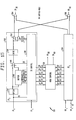
- a single switch 804 is illustrated in figure 20.
- the lead z- is perpendicular to the plane of the cross connect and extend outward from one side thereof.
- the lead z + is also perpendicular to the plane of the cross connect and extends outward from the other side thereof, while the leads that lie in the plane of the cross connect 802 are labeled x- and x +.
- the four possible configurations of the switch 804 of figure 20 are z- to z + (straight through the plane) x- to z +, x- to x + (along the surface of the plane at a 45 degree angle to the rows of switches) and z- to x + .
- Figure 21 shows a circuit for implementing the switch 804 of figure's 19 and 20.
- the flip flops 806, 808 provide control signals to the data selector 810 and gates 812, 814 to determine which of the four possible connections between the leads x +, x-, z +, z- is made. All of the flip-flops in the same row of switches are linked together as one long shift register with the individual flip-flops forming the bits of the shift register. To change the configuration of the cross connect 802, new data values are inputted to the shift registers.
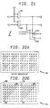
- FIG 22 provides some examples of the type of connections which can be achieved using the cross-connect discussed above.
- the cross connect 900 of figures 22(a) and 22(b) has 8 rows and 16 columns of switches.
- Front end switch modules (FSMs) are connected to one side of the cross-connect 900, while BSMs (back-end switch modules) are connected to the other side of the cross-connect 900.
- FSMs Front end switch modules
- BSMs back-end switch modules
- Figure 22(a) shows a situation in which a single BSM is connected with two FSM's.
- the BSM is connected to one side of the cross-connect plane, the FSM being connected to the other side.
- Eight fiber-optic links from the first FSM terminate at the switches located in the first column of the cross connect 900.
- Eight fiber optic links of the second FSM terminate at the switches located in the ninth column of the cross-connect.
- Sixteen fiber optic links from the BSM terminate at switches located in the first row of the cross-connect.
- the switches that make up the cross-connect are arranged so that signals from the FSM's are switched up and to the right along paths 906 as shown in figure 9(a) so that they leave through switches on the top row of the cross-connect 900 which switches terminate fiber optic links of the single BSM.
- the signals fed into switches 902, 904, pass right through the plane of the cross connect. There are thus eight paths 906 connecting each of two FSMs to the BSM.
- Figure 22(b) shows a configuration in which four FSM's are connected to on one side of the cross-connect plane and two BSM's are connected to the other side of the cross-connect plane.
- Eight fiber optic links from each of the four FSM's terminate at the switches comprising columns 1, 5, 9 and 13, respectively.
- Eight fiber optic links from each of the two BSM's terminate on the switches comprising rows 1 and 4 respectively.
- the switches comprising the cross connect 900 are programmed so that there are four paths connecting each FSM to each BSM. Thus, increasing the size of a packet switch from three switch modules to six switch modules may be accomplished merely by reprogramming the switches in the cross connect.
- the cross connect 900 of figure 22 is an 8 x 16 array which may be viewed as having 128 inputs on one side of the planar array and 128 outputs on the other side of the planar array. If the number of inputs and outputs is to be increased to 256, a 16 x 16 array is needed, which essentially doubles the size of the cross connect.
- the cross connect described herein grows linearly in size as the number of inputs and outputs increases. This follows directly from the fact that the cross connect utilizes both sides of a planar array to interconnect sets of switch modules.
Landscapes
- Engineering & Computer Science (AREA)
- Computer Networks & Wireless Communication (AREA)
- Signal Processing (AREA)
- Physics & Mathematics (AREA)
- Mathematical Physics (AREA)
- Data Exchanges In Wide-Area Networks (AREA)
- Materials For Medical Uses (AREA)
- Use Of Switch Circuits For Exchanges And Methods Of Control Of Multiplex Exchanges (AREA)
Claims (19)
Priority Applications (1)
| Application Number | Priority Date | Filing Date | Title |
|---|---|---|---|
| AT86401052T ATE84653T1 (de) | 1985-09-06 | 1986-05-16 | Paketvermittlungsnetzwerk mit rundsendefaehigkeit. |
Applications Claiming Priority (2)
| Application Number | Priority Date | Filing Date | Title |
|---|---|---|---|
| US06/773,380 US4734907A (en) | 1985-09-06 | 1985-09-06 | Broadcast packet switching network |
| US773380 | 1985-09-06 |
Publications (3)
| Publication Number | Publication Date |
|---|---|
| EP0260364A2 EP0260364A2 (fr) | 1988-03-23 |
| EP0260364A3 EP0260364A3 (en) | 1989-06-14 |
| EP0260364B1 true EP0260364B1 (fr) | 1993-01-13 |
Family
ID=25098074
Family Applications (1)
| Application Number | Title | Priority Date | Filing Date |
|---|---|---|---|
| EP86401052A Expired - Lifetime EP0260364B1 (fr) | 1985-09-06 | 1986-05-16 | Réseau de commutation de paquets avec capacité de diffusion |
Country Status (6)
| Country | Link |
|---|---|
| US (4) | US4734907A (fr) |
| EP (1) | EP0260364B1 (fr) |
| JP (1) | JP2512435B2 (fr) |
| AT (1) | ATE84653T1 (fr) |
| CA (1) | CA1254985A (fr) |
| DE (1) | DE3687525T2 (fr) |
Families Citing this family (216)
| Publication number | Priority date | Publication date | Assignee | Title |
|---|---|---|---|---|
| US4965825A (en) | 1981-11-03 | 1990-10-23 | The Personalized Mass Media Corporation | Signal processing apparatus and methods |
| USRE47642E1 (en) | 1981-11-03 | 2019-10-08 | Personalized Media Communications LLC | Signal processing apparatus and methods |
| US7831204B1 (en) | 1981-11-03 | 2010-11-09 | Personalized Media Communications, Llc | Signal processing apparatus and methods |
| CA1292053C (fr) | 1986-09-16 | 1991-11-12 | Yoshito Sakurai | Systeme a repartition temporelle |
| IT1196791B (it) * | 1986-11-18 | 1988-11-25 | Cselt Centro Studi Lab Telecom | Elemento di commutazione per reti di interconnessione multistadio autoinstradanti a commutazione di pacchetto |
| BE905982A (fr) * | 1986-12-19 | 1987-06-19 | Electronique Et Telecomm Bell | Reseau de commutation de paquets. |
| BE1000258A6 (nl) * | 1987-01-16 | 1988-09-27 | Bell Telephone Mfg | Informatie-overdrachtsysteem. |
| US4813038A (en) * | 1987-06-29 | 1989-03-14 | Bell Communications Research, Inc. | Non-blocking copy network for multicast packet switching |
| US5195092A (en) * | 1987-08-04 | 1993-03-16 | Telaction Corporation | Interactive multimedia presentation & communication system |
| EP0310759B1 (fr) * | 1987-09-30 | 1993-06-16 | Siemens Aktiengesellschaft | Opérateur de tri pour noeud de commutation avec une pluralité de champs de connexion numériques pour réseaux rapides de commutation asynchrone par paquets |
| US5245603A (en) * | 1987-10-15 | 1993-09-14 | Network Equipment Technologies, Inc. | High-speed determining unit for prioritizing and arbitrating among competing input signals |
| US5222085A (en) * | 1987-10-15 | 1993-06-22 | Peter Newman | Self-routing switching element and fast packet switch |
| US5367518A (en) * | 1987-10-15 | 1994-11-22 | Network Equipment Technologies, Inc. | Self-routing switching element and fast packet switch |
| GB8724208D0 (en) * | 1987-10-15 | 1987-11-18 | Newman P | Self-routing switching element |
| US4887076A (en) * | 1987-10-16 | 1989-12-12 | Digital Equipment Corporation | Computer interconnect coupler for clusters of data processing devices |
| FR2624801B1 (fr) * | 1987-12-16 | 1990-04-13 | Michelin & Cie | Elements necessaires a l'excitation et a l'ecoute des modules de roues dans un systeme de surveillance des roues d'un vehicule |
| US5251308A (en) * | 1987-12-22 | 1993-10-05 | Kendall Square Research Corporation | Shared memory multiprocessor with data hiding and post-store |
| US5226039A (en) * | 1987-12-22 | 1993-07-06 | Kendall Square Research Corporation | Packet routing switch |
| US5055999A (en) * | 1987-12-22 | 1991-10-08 | Kendall Square Research Corporation | Multiprocessor digital data processing system |
| US5761413A (en) * | 1987-12-22 | 1998-06-02 | Sun Microsystems, Inc. | Fault containment system for multiprocessor with shared memory |
| US5822578A (en) * | 1987-12-22 | 1998-10-13 | Sun Microsystems, Inc. | System for inserting instructions into processor instruction stream in order to perform interrupt processing |
| US5341483A (en) * | 1987-12-22 | 1994-08-23 | Kendall Square Research Corporation | Dynamic hierarchial associative memory |
| JPH01165246A (ja) * | 1987-12-22 | 1989-06-29 | Oki Electric Ind Co Ltd | パケット交換方式 |
| FR2625858A1 (fr) * | 1988-01-08 | 1989-07-13 | Lmt Radio Professionelle | Procede et dispositif de commutation d'un paquet de donnees |
| JP2659421B2 (ja) * | 1988-02-17 | 1997-09-30 | 日本電信電話株式会社 | 自己ルーチング通話路 |
| CA1331801C (fr) * | 1988-03-17 | 1994-08-30 | Yasuro Shobatake | Commutateur de paques |
| US4870641A (en) * | 1988-03-30 | 1989-09-26 | Bell Communications Research, Inc. | Multichannel bandwidth allocation |
| JP2667868B2 (ja) * | 1988-04-06 | 1997-10-27 | 株式会社日立製作所 | セル・スイッチング・システム |
| US5377327A (en) * | 1988-04-22 | 1994-12-27 | Digital Equipment Corporation | Congestion avoidance scheme for computer networks |
| JP2682847B2 (ja) * | 1988-07-21 | 1997-11-26 | 株式会社日立製作所 | パケット交換網の中継ループ迂回方法 |
| US5396491A (en) * | 1988-10-14 | 1995-03-07 | Network Equipment Technologies, Inc. | Self-routing switching element and fast packet switch |
| IT1224493B (it) * | 1988-10-17 | 1990-10-04 | Cselt Centro Studi Lab Telecom | Interfaccia di controllo e commutazione di etichetta per commutazione veloce di pacchetto asincrona |
| JPH02117243A (ja) * | 1988-10-27 | 1990-05-01 | Toshiba Corp | パケット通信装置 |
| SE462360B (sv) * | 1988-10-28 | 1990-06-11 | Ellemtel Utvecklings Ab | Foerfarande och anordning foer att foerhindra att det paa en gemensam oeverfoeringslaenk saends datapaket med hoegre intensitet aen ettfoerutbestaemt vaerdesitet aen ett foerutbestaemt vaerde |
| US5369775A (en) * | 1988-12-20 | 1994-11-29 | Mitsubishi Denki Kabushiki Kaisha | Data-flow processing system having an input packet limiting section for preventing packet input based upon a threshold value indicative of an optimum pipeline processing capacity |
| JP2753294B2 (ja) * | 1988-12-23 | 1998-05-18 | 株式会社日立製作所 | パケット輻輳制御方法およびパケット交換装置 |
| US4953159A (en) * | 1989-01-03 | 1990-08-28 | American Telephone And Telegraph Company | Audiographics conferencing arrangement |
| US5175539A (en) * | 1989-01-24 | 1992-12-29 | Max-Planck-Gesellschaft Zur Foerderung Der Wissenschaften E.V. | Interconnecting network |
| US5140584A (en) * | 1989-03-01 | 1992-08-18 | Kabushiki Kaisha Toshiba | Packet communication system and method of controlling same |
| ATE107452T1 (de) * | 1989-03-03 | 1994-07-15 | Siemens Ag | Verfahren und schaltungsanordnung zum weiterleiten von auf zubringerleitungen übertragenen nachrichtenpaketen über eine paketvermittlungseinrichtung. |
| JP2986802B2 (ja) * | 1989-03-13 | 1999-12-06 | 株式会社日立製作所 | プロトコル高速処理方法 |
| NL8900640A (nl) * | 1989-03-16 | 1990-10-16 | At & T & Philips Telecomm | Werkwijze voor het in atd (asynchronous time division) overdragen van datapakketten en een inrichting voor toepassing van deze werkwijze. |
| US5077483A (en) * | 1989-05-08 | 1991-12-31 | At&T Bell Laboratories | Network topology for reduced blocking and photonic system implementation thereof |
| US5475680A (en) * | 1989-09-15 | 1995-12-12 | Gpt Limited | Asynchronous time division multiplex switching system |
| US4991171A (en) * | 1989-09-26 | 1991-02-05 | At&T Bell Laboratories | Broadcast packet switch network |
| US5001702A (en) * | 1989-09-26 | 1991-03-19 | At&T Bell Laboratories | Packet switching network for multiple packet types |
| JPH03135133A (ja) * | 1989-10-20 | 1991-06-10 | Toshiba Corp | マルチメディア統合ネットワークシステム |
| EP0425990B1 (fr) * | 1989-10-23 | 1998-07-22 | Mitsubishi Denki Kabushiki Kaisha | Appareil de commutation de cellules |
| FR2655795A1 (fr) * | 1989-12-07 | 1991-06-14 | Cit Alcatel | Reseau local de transmission de donnees. |
| JPH03198449A (ja) * | 1989-12-27 | 1991-08-29 | Toshiba Corp | パケット交換網のパケット廃棄制御方式 |
| ES2076389T3 (es) * | 1990-03-14 | 1995-11-01 | Alcatel Nv | Elemento de conmutacion de tipo amt con varios modos de funcionamiento y red de conmutacion que lo comprende. |
| ATE114912T1 (de) * | 1990-03-14 | 1994-12-15 | Alcatel Nv | Anordnung zur leitweglenkung für ein kommunikations-vermittlungselement. |
| FR2659818B1 (fr) * | 1990-03-14 | 1995-01-20 | Cit Alcatel | Commutateur elementaire pour la commutation de cellules a multiplexage temporel asynchrone et reseau de commutation en faisant application. |
| US5153595A (en) * | 1990-03-26 | 1992-10-06 | Geophysical Survey Systems, Inc. | Range information from signal distortions |
| US5119368A (en) * | 1990-04-10 | 1992-06-02 | At&T Bell Laboratories | High-speed time-division switching system |
| US5103444A (en) * | 1990-04-12 | 1992-04-07 | At&T Bell Laboratories | Conference connection method in a multicast packet switching network |
| DE59007068D1 (de) * | 1990-04-27 | 1994-10-13 | Siemens Ag | Verfahren und Schaltungsanordnung zur Reduzierung des Verlustes von Nachrichtenpaketen, die über eine Paketvermittlungseinrichtung übertragen werden. |
| US5261059A (en) * | 1990-06-29 | 1993-11-09 | Digital Equipment Corporation | Crossbar interface for data communication network |
| US5117422A (en) * | 1990-07-09 | 1992-05-26 | Itt Corporation | Method for providing an efficient and adaptive management of message routing in a multi-platform and apparatus communication system |
| JP3128654B2 (ja) | 1990-10-19 | 2001-01-29 | 富士通株式会社 | 監視制御方法、監視制御装置及び交換システム |
| DE69022055T2 (de) * | 1990-11-06 | 1996-03-07 | Hewlett Packard Co | Schaltungseinrichtungen und Verfahren für Vielfachübertragung. |
| US5121383A (en) * | 1990-11-16 | 1992-06-09 | Bell Communications Research, Inc. | Duration limited statistical multiplexing in packet networks |
| AR247460A1 (es) * | 1990-11-30 | 1994-12-29 | Motorola Inc | Una disposicion de rf multiusuario donde la informacion se comunica por paquetes, y metodo para implementarla |
| US5297137A (en) * | 1991-01-30 | 1994-03-22 | International Business Machines Corporation | Process for routing data packets around a multi-node communications network |
| US5229991A (en) * | 1991-01-30 | 1993-07-20 | Washington University | Packet switch with broadcasting capability for atm networks |
| JPH05304686A (ja) * | 1991-04-30 | 1993-11-16 | Nec Corp | クロスコネクト装置 |
| US5321813A (en) * | 1991-05-01 | 1994-06-14 | Teradata Corporation | Reconfigurable, fault tolerant, multistage interconnect network and protocol |
| ATE149276T1 (de) * | 1991-05-08 | 1997-03-15 | Semaphore Inc | Gerät und verfahren zur parallelen und regelgestützten datenübertragung |
| US5313458A (en) * | 1991-06-03 | 1994-05-17 | Fujitsu Limited | Traffic control system |
| EP0519563A3 (en) * | 1991-06-21 | 1997-08-27 | Koninkl Philips Electronics Nv | System for converting synchronous time-division-multiplex signals into asynchronous time-division data packets |
| US5293486A (en) * | 1991-06-28 | 1994-03-08 | Digital Equipment Corporation | Deterministic method for allocation of a shared resource |
| ES2068485T3 (es) * | 1991-07-22 | 1995-04-16 | Alcatel Nv | Sistema de telecomunicacion para transmitir celulas a traves de nodos de conmutacion interconectados por grupos de enlaces de transmision. |
| US5233606A (en) * | 1991-08-02 | 1993-08-03 | At&T Bell Laboratories | Arrangement for controlling shared-buffer-memory overflow in a multi-priority environment |
| US5179556A (en) * | 1991-08-02 | 1993-01-12 | Washington University | Bandwidth management and congestion control scheme for multicast ATM networks |
| DE4128411A1 (de) * | 1991-08-27 | 1993-03-04 | Siemens Ag | Anordnung zur bitratenueberwachung in atm-netzen |
| CA2078310A1 (fr) * | 1991-09-20 | 1993-03-21 | Mark A. Kaufman | Processeur numerique a memoire repartie |
| CA2078312A1 (fr) | 1991-09-20 | 1993-03-21 | Mark A. Kaufman | Processeur de donnees numeriques a pagination amelioree |
| EP0542406B1 (fr) * | 1991-11-14 | 1998-04-08 | Hewlett-Packard Company | Dispositif et procédé d'estimation des hauts contributeurs |
| JP2671699B2 (ja) * | 1991-11-15 | 1997-10-29 | 三菱電機株式会社 | セル交換装置 |
| US5398235A (en) * | 1991-11-15 | 1995-03-14 | Mitsubishi Denki Kabushiki Kaisha | Cell exchanging apparatus |
| US5390299A (en) * | 1991-12-27 | 1995-02-14 | Digital Equipment Corporation | System for using three different methods to report buffer memory occupancy information regarding fullness-related and/or packet discard-related information |
| US5426640A (en) * | 1992-01-21 | 1995-06-20 | Codex Corporation | Rate-based adaptive congestion control system and method for integrated packet networks |
| US5276679A (en) * | 1992-02-12 | 1994-01-04 | U.S. West Advanced Technologies, Inc. | Method for maintaining channels and a subscriber station for use in an ISDN system |
| SE470002B (sv) * | 1992-03-13 | 1993-10-18 | Ellemtel Utvecklings Ab | Förfarande för att förhindra att det på någon av ett antal kanaler på en gemensam överföringsledning sänds datapaket med högre intensitet än ett för kanalen förutbestämt värde samt anordning för utövande av sättet |
| US5243596A (en) * | 1992-03-18 | 1993-09-07 | Fischer & Porter Company | Network architecture suitable for multicasting and resource locking |
| JPH0614049A (ja) * | 1992-03-19 | 1994-01-21 | Fujitsu Ltd | Atmにおけるセル廃棄制御装置及びその方法 |
| US5274642A (en) * | 1992-06-05 | 1993-12-28 | Indra Widjaja | Output buffered packet switch with a flexible buffer management scheme |
| US5327552A (en) * | 1992-06-22 | 1994-07-05 | Bell Communications Research, Inc. | Method and system for correcting routing errors due to packet deflections |
| US5276681A (en) * | 1992-06-25 | 1994-01-04 | Starlight Networks | Process for fair and prioritized access to limited output buffers in a multi-port switch |
| US5335224A (en) * | 1992-06-30 | 1994-08-02 | At&T Bell Laboratories | Service guarantees/congestion control in high speed networks |
| JP3483900B2 (ja) * | 1992-07-08 | 2004-01-06 | 株式会社日立製作所 | 同報通信方法 |
| US5539740A (en) * | 1992-07-20 | 1996-07-23 | Siemens Aktiengesellschaft | Method for forwarding a message cell stream via a plurality of parallel trunks while adhering to the sequence of the message cells |
| IT1255810B (it) * | 1992-08-07 | 1995-11-16 | Alcatel Italia | Rete di connessione fotonica a commutazione di pacchetto per la diffusione d'informazioni |
| GB2272612B (en) * | 1992-11-06 | 1996-05-01 | Roke Manor Research | Improvements in or relating to ATM signal processors |
| US5341375A (en) * | 1992-11-12 | 1994-08-23 | Motorola, Inc. | Transmission of broadcast packets in an RF system |
| ES2168093T3 (es) * | 1992-11-19 | 2002-06-01 | Ibm | Distribucion de funcion en una red de conmutacion de paquetes. |
| DE69433229T2 (de) * | 1993-02-15 | 2004-08-12 | Mitsubishi Denki K.K. | ATM-Schalter |
| EP0625855A1 (fr) * | 1993-05-19 | 1994-11-23 | ALCATEL BELL Naamloze Vennootschap | Réseau assurant des services vidéo commutés |
| JP3211833B2 (ja) * | 1993-07-21 | 2001-09-25 | 富士通株式会社 | Atm交換機 |
| JPH0766833A (ja) * | 1993-08-24 | 1995-03-10 | Mitsubishi Electric Corp | フレーム中継装置、フレーム中継装置群及び中継方法 |
| US5528763A (en) * | 1993-09-14 | 1996-06-18 | International Business Machines Corporation | System for admitting cells of packets from communication network into buffer of attachment of communication adapter |
| US5416770A (en) * | 1993-09-15 | 1995-05-16 | Motorola, Inc. | Method and apparatus for establishing dispatch audio communication in a communication system |
| JP2746283B2 (ja) * | 1993-12-28 | 1998-05-06 | 日本電気株式会社 | 通信システム |
| US5528592A (en) * | 1994-01-27 | 1996-06-18 | Dsc Communications Corporation | Method and apparatus for route processing asynchronous transfer mode cells |
| US5453979A (en) * | 1994-01-27 | 1995-09-26 | Dsc Communications Corporation | Method and apparatus for generating route information for asynchronous transfer mode cell processing |
| US5452293A (en) * | 1994-01-27 | 1995-09-19 | Dsc Communications Corporation | Apparatus and method of transmitting call information prior to establishing a connection path |
| US5617409A (en) * | 1994-01-28 | 1997-04-01 | Digital Equipment Corporation | Flow control with smooth limit setting for multiple virtual circuits |
| US5455826A (en) * | 1994-06-28 | 1995-10-03 | Oezveren; Cueneyt M. | Method and apparatus for rate based flow control |
| US5629936A (en) * | 1994-08-01 | 1997-05-13 | University Of Iowa Research Foundation Inc. | Control of consecutive packet loss in a packet buffer |
| US5633859A (en) * | 1994-09-16 | 1997-05-27 | The Ohio State University | Method and apparatus for congestion management in computer networks using explicit rate indication |
| US5550818A (en) * | 1994-09-19 | 1996-08-27 | Bell Communications Research, Inc. | System for wavelength division multiplexing/asynchronous transfer mode switching for network communication |
| JP2829255B2 (ja) * | 1995-05-24 | 1998-11-25 | 日本電信電話株式会社 | Atm交換装置 |
| GB9511314D0 (en) * | 1995-06-05 | 1995-08-02 | Gen Datacomm Adv Res | ATM network switch with congestion control |
| US5734843A (en) * | 1995-06-07 | 1998-03-31 | Advanced Micro Devices Inc. | Reverse data channel as a bandwidth modulator |
| US5809221A (en) * | 1995-06-07 | 1998-09-15 | Cornet, Inc. | Apparatus and method for detecting and bypassing faulty switches in a digital matrix switch |
| US5870538A (en) * | 1995-07-19 | 1999-02-09 | Fujitsu Network Communications, Inc. | Switch fabric controller comparator system and method |
| WO1997010656A1 (fr) * | 1995-09-14 | 1997-03-20 | Fujitsu Network Communications, Inc. | Commande de flux commande par emetteur pour attribution de tampons dans des reseaux mta longue distance |
| US5892932A (en) * | 1995-11-21 | 1999-04-06 | Fore Systems, Inc. | Reprogrammable switching apparatus and method |
| US5566181A (en) * | 1995-11-29 | 1996-10-15 | Motorola, Inc. | Method and system for establishing a communication using geographically distributed packet duplicators |
| US5940377A (en) * | 1995-12-21 | 1999-08-17 | Kabushiki Kaisha Toshiba | Asynchronous transfer mode switch including cell counter verification circuitry |
| JP2000517488A (ja) * | 1996-01-16 | 2000-12-26 | フジツウ ネットワーク コミュニケーションズ,インコーポレイテッド | Atm網用の信頼性と柔軟性のあるマルチキャスト機構 |
| US6542502B1 (en) * | 1996-01-26 | 2003-04-01 | International Business Machines Corporation | Multicasting using a wormhole routing switching element |
| JP3156752B2 (ja) * | 1996-02-09 | 2001-04-16 | 日本電気株式会社 | Atmスイッチ装置及びその制御方法 |
| US5740375A (en) * | 1996-02-15 | 1998-04-14 | Bay Networks, Inc. | Forwarding internetwork packets by replacing the destination address |
| US5724358A (en) * | 1996-02-23 | 1998-03-03 | Zeitnet, Inc. | High speed packet-switched digital switch and method |
| US5777988A (en) * | 1996-04-17 | 1998-07-07 | Bell Communications Research, Inc. | System and method for equalizing delay in a dynamic packet switching network |
| US6034945A (en) * | 1996-05-15 | 2000-03-07 | Cisco Technology, Inc. | Method and apparatus for per traffic flow buffer management |
| US5687173A (en) * | 1996-07-10 | 1997-11-11 | Cascade Communications Corp. | Addressable high speed counter array |
| US5898687A (en) * | 1996-07-24 | 1999-04-27 | Cisco Systems, Inc. | Arbitration mechanism for a multicast logic engine of a switching fabric circuit |
| US6188675B1 (en) * | 1996-08-23 | 2001-02-13 | International Business Machines Corporation | System and method for self-identifying and configuring the nodes of a network |
| US5748905A (en) * | 1996-08-30 | 1998-05-05 | Fujitsu Network Communications, Inc. | Frame classification using classification keys |
| US6031843A (en) * | 1996-11-21 | 2000-02-29 | Alcatel Data Networks Inc. | Digital communications switching fabric |
| US6185223B1 (en) * | 1996-12-04 | 2001-02-06 | Conexant Systems, Inc. | Apparatus and method for providing fire wall protection for systems in communication with an a synchronous transfer mode system |
| US6249819B1 (en) | 1996-12-06 | 2001-06-19 | Fujitsu Network Communications, Inc. | Method for flow controlling ATM traffic |
| US5916302A (en) * | 1996-12-06 | 1999-06-29 | International Business Machines Corporation | Multimedia conferencing using parallel networks |
| US6124878A (en) * | 1996-12-20 | 2000-09-26 | Time Warner Cable, A Division Of Time Warner Enterainment Company, L.P. | Optimum bandwidth utilization in a shared cable system data channel |
| US6052753A (en) * | 1997-01-21 | 2000-04-18 | Alliedsignal Inc. | Fault tolerant data bus |
| JP3156623B2 (ja) | 1997-01-31 | 2001-04-16 | 日本電気株式会社 | ファイバチャネルファブリック |
| US6487202B1 (en) | 1997-06-30 | 2002-11-26 | Cisco Technology, Inc. | Method and apparatus for maximizing memory throughput |
| US6430191B1 (en) | 1997-06-30 | 2002-08-06 | Cisco Technology, Inc. | Multi-stage queuing discipline |
| JP2959540B2 (ja) * | 1997-10-03 | 1999-10-06 | 日本電気株式会社 | ノード装置 |
| JP3383199B2 (ja) | 1997-10-13 | 2003-03-04 | 富士通株式会社 | 中継装置および中継装置における負荷分散伝送方法 |
| US6526060B1 (en) | 1997-12-05 | 2003-02-25 | Cisco Technology, Inc. | Dynamic rate-based, weighted fair scheduler with explicit rate feedback option |
| US6614781B1 (en) * | 1998-11-20 | 2003-09-02 | Level 3 Communications, Inc. | Voice over data telecommunications network architecture |
| US6747984B1 (en) | 1998-12-18 | 2004-06-08 | Lsi Logic Corporation | Method and apparatus for transmitting Data |
| US7206877B1 (en) | 1998-12-22 | 2007-04-17 | Honeywell International Inc. | Fault tolerant data communication network |
| US20060174052A1 (en) * | 2005-02-02 | 2006-08-03 | Nobukazu Kondo | Integrated circuit and information processing device |
| US6745240B1 (en) | 1999-11-15 | 2004-06-01 | Ncr Corporation | Method and apparatus for configuring massively parallel systems |
| US6519697B1 (en) | 1999-11-15 | 2003-02-11 | Ncr Corporation | Method and apparatus for coordinating the configuration of massively parallel systems |
| US6418526B1 (en) | 1999-11-15 | 2002-07-09 | Ncr Corporation | Method and apparatus for synchronizing nodes in massively parallel systems |
| US6412002B1 (en) | 1999-11-15 | 2002-06-25 | Ncr Corporation | Method and apparatus for selecting nodes in configuring massively parallel systems |
| US6775292B1 (en) | 2000-01-24 | 2004-08-10 | Cisco Technology, Inc. | Method for servicing of multiple queues carrying voice over virtual circuits based on history |
| US6985455B1 (en) * | 2000-03-03 | 2006-01-10 | Hughes Electronics Corporation | Method and system for providing satellite bandwidth on demand using multi-level queuing |
| US6728211B1 (en) | 2000-03-07 | 2004-04-27 | Cisco Technology, Inc. | Method and apparatus for delaying packets being sent from a component of a packet switching system |
| US6674721B1 (en) | 2000-03-07 | 2004-01-06 | Cisco Technology, Inc. | Method and apparatus for scheduling packets being sent from a component of a packet switching system |
| US6788689B1 (en) | 2000-03-07 | 2004-09-07 | Cisco Technology, Inc. | Route scheduling of packet streams to achieve bounded delay in a packet switching system |
| US6757284B1 (en) | 2000-03-07 | 2004-06-29 | Cisco Technology, Inc. | Method and apparatus for pipeline sorting of ordered streams of data items |
| US6907041B1 (en) | 2000-03-07 | 2005-06-14 | Cisco Technology, Inc. | Communications interconnection network with distributed resequencing |
| US6735173B1 (en) | 2000-03-07 | 2004-05-11 | Cisco Technology, Inc. | Method and apparatus for accumulating and distributing data items within a packet switching system |
| US6747972B1 (en) | 2000-03-07 | 2004-06-08 | Cisco Technology, Inc. | Method and apparatus for reducing the required size of sequence numbers used in resequencing packets |
| US6990063B1 (en) * | 2000-03-07 | 2006-01-24 | Cisco Technology, Inc. | Distributing fault indications and maintaining and using a data structure indicating faults to route traffic in a packet switching system |
| US6654342B1 (en) | 2000-03-07 | 2003-11-25 | Cisco Technology, Inc. | Accumulating and distributing flow control information via update messages and piggybacked flow control information in other messages in a packet switching system |
| US7142558B1 (en) | 2000-04-17 | 2006-11-28 | Cisco Technology, Inc. | Dynamic queuing control for variable throughput communication channels |
| US6816492B1 (en) | 2000-07-31 | 2004-11-09 | Cisco Technology, Inc. | Resequencing packets at output ports without errors using packet timestamps and timestamp floors |
| US6813267B1 (en) * | 2000-09-11 | 2004-11-02 | Sun Microsystems, Inc. | Tunable broadcast/point-to-point packet arbitration |
| US7054263B1 (en) * | 2000-10-16 | 2006-05-30 | Telefonaktiebolaget Lm Ericsson (Publ) | Synchronous change of switchplane |
| US7012889B1 (en) | 2000-11-02 | 2006-03-14 | Cisco Technology, Inc. | Method and apparatus for controlling input rates within a packet switching system |
| US7106693B1 (en) | 2000-11-02 | 2006-09-12 | Cisco Technology, Inc. | Method and apparatus for pacing the flow of information sent from a device |
| US6879560B1 (en) * | 2000-12-08 | 2005-04-12 | At&T Corp. | System and method for limiting congestion over a switch network |
| US6967926B1 (en) | 2000-12-31 | 2005-11-22 | Cisco Technology, Inc. | Method and apparatus for using barrier phases to limit packet disorder in a packet switching system |
| US6934760B1 (en) | 2001-02-04 | 2005-08-23 | Cisco Technology, Inc. | Method and apparatus for resequencing of packets into an original ordering using multiple resequencing components |
| US7092393B1 (en) | 2001-02-04 | 2006-08-15 | Cisco Technology, Inc. | Method and apparatus for distributed reassembly of subdivided packets using multiple reassembly components |
| US6832261B1 (en) | 2001-02-04 | 2004-12-14 | Cisco Technology, Inc. | Method and apparatus for distributed resequencing and reassembly of subdivided packets |
| US6937562B2 (en) | 2001-02-05 | 2005-08-30 | Ipr Licensing, Inc. | Application specific traffic optimization in a wireless link |
| US7027397B1 (en) | 2001-02-15 | 2006-04-11 | Cisco Technology, Inc. | Method and apparatus for accumulating and distributing traffic and flow control information in a packet switching system |
| FR2821509B1 (fr) * | 2001-02-27 | 2003-05-30 | Thomson Csf | Procede et dispositif pour transferer des donnees dans un reseau de communication comportant une artere a faible debit |
| US6870844B2 (en) * | 2001-03-06 | 2005-03-22 | Pluris, Inc. | Apparatus and methods for efficient multicasting of data packets |
| US6834138B2 (en) * | 2001-03-06 | 2004-12-21 | Corning Incorporated | Modular optical switch fabric |
| WO2002093828A2 (fr) * | 2001-05-17 | 2002-11-21 | Solidum Systems Corporation | Systeme distribue de traitement de paquets avec distribution de la charge interne |
| US7016305B1 (en) | 2001-06-27 | 2006-03-21 | Cisco Technology, Inc | Method and apparatus for distributing information within a packet switching system |
| US7269139B1 (en) | 2001-06-27 | 2007-09-11 | Cisco Technology, Inc. | Method and apparatus for an adaptive rate control mechanism reactive to flow control messages in a packet switching system |
| US7389359B2 (en) | 2001-10-19 | 2008-06-17 | Foundry Networks, Inc. | Method and system for intelligently forwarding multicast packets |
| US7647422B2 (en) * | 2001-11-06 | 2010-01-12 | Enterasys Networks, Inc. | VPN failure recovery |
| JP3970581B2 (ja) * | 2001-11-09 | 2007-09-05 | 富士通株式会社 | 伝送装置および伝送システム |
| US20030097661A1 (en) * | 2001-11-16 | 2003-05-22 | Li Hua Harry | Time-shifted television over IP network system |
| US7403999B2 (en) * | 2001-12-28 | 2008-07-22 | International Business Machines Corporation | Classification support system and method for fragmented IP packets |
| US7613200B1 (en) | 2002-01-15 | 2009-11-03 | Cisco Technology, Inc. | Method and apparatus using a random indication to map items to paths and to recirculate or delay the sending of a particular item when a destination over its mapped path is unreachable |
| US7266612B1 (en) * | 2002-02-14 | 2007-09-04 | At&T Corp. | Network having overload control using deterministic early active drops |
| US7739402B2 (en) * | 2002-03-01 | 2010-06-15 | Enterasys Networks, Inc. | Locating devices in a data network |
| US7075940B1 (en) | 2002-05-06 | 2006-07-11 | Cisco Technology, Inc. | Method and apparatus for generating and using dynamic mappings between sets of entities such as between output queues and ports in a communications system |
| US7304999B2 (en) * | 2002-08-24 | 2007-12-04 | Cisco Technology Inc. | Methods and apparatus for processing packets including distributing packets across multiple packet processing engines and gathering the processed packets from the processing engines |
| US7404015B2 (en) * | 2002-08-24 | 2008-07-22 | Cisco Technology, Inc. | Methods and apparatus for processing packets including accessing one or more resources shared among processing engines |
| US7051259B1 (en) | 2002-10-08 | 2006-05-23 | Cisco Technology, Inc. | Methods and apparatus for communicating time and latency sensitive information |
| US7313093B1 (en) | 2002-11-26 | 2007-12-25 | Cisco Technology, Inc. | Methods and apparatus for selectively discarding packets during overload conditions |
| US7296100B1 (en) | 2003-10-06 | 2007-11-13 | Redpine Signals, Inc. | Packet buffer management apparatus and method |
| KR100612442B1 (ko) * | 2004-01-26 | 2006-08-16 | 삼성전자주식회사 | 버퍼형 스위치 및 그 스케쥴링 방법 |
| US7580403B2 (en) * | 2004-02-26 | 2009-08-25 | Enterasys Networks, Inc. | Status transmission system and method |
| US20050195756A1 (en) * | 2004-02-26 | 2005-09-08 | Frattura David E. | Status announcement system and method |
| US20060037075A1 (en) * | 2004-03-10 | 2006-02-16 | Frattura David E | Dynamic network detection system and method |
| US7945945B2 (en) * | 2004-08-06 | 2011-05-17 | Enterasys Networks, Inc. | System and method for address block enhanced dynamic network policy management |
| US7555584B2 (en) * | 2004-09-29 | 2009-06-30 | Intel Corporation | Providing additional channels for an MSL architecture |
| US7347628B2 (en) | 2004-11-08 | 2008-03-25 | Enterasys Networks, Inc. | Optical interface identification system |
| US7551617B2 (en) | 2005-02-08 | 2009-06-23 | Cisco Technology, Inc. | Multi-threaded packet processing architecture with global packet memory, packet recirculation, and coprocessor |
| US8086232B2 (en) * | 2005-06-28 | 2011-12-27 | Enterasys Networks, Inc. | Time synchronized wireless method and operations |
| US8155118B2 (en) * | 2005-08-19 | 2012-04-10 | Hewlett-Packard Development Company, L.P. | Mirroring of a random subset of network traffic |
| US7558200B2 (en) * | 2005-09-01 | 2009-07-07 | Microsoft Corporation | Router congestion management |
| US7739426B1 (en) | 2005-10-31 | 2010-06-15 | Cisco Technology, Inc. | Descriptor transfer logic |
| US7809009B2 (en) * | 2006-02-21 | 2010-10-05 | Cisco Technology, Inc. | Pipelined packet switching and queuing architecture |
| JP4977378B2 (ja) | 2006-02-23 | 2012-07-18 | 山梨日本電気株式会社 | 磁気センサ、回転検出装置及び位置検出装置 |
| WO2007108054A1 (fr) * | 2006-03-16 | 2007-09-27 | Fujitsu Limited | Noeud de communication et procede de selection de route de communication |
| US20070253426A1 (en) * | 2006-04-28 | 2007-11-01 | International Business Machines Corporation | Reliable global broadcasting in a multistage network |
| US8054847B2 (en) * | 2006-10-31 | 2011-11-08 | Hewlett-Packard Development Company, L.P. | Buffer management in a network device |
| US8324329B2 (en) * | 2007-08-07 | 2012-12-04 | Bridgestone Corporation | Process for producing functionalized polymers |
| US7801046B2 (en) * | 2008-04-28 | 2010-09-21 | Oracle America, Inc. | Method and system for bandwidth control on a network interface card |
| US9001663B2 (en) * | 2010-02-26 | 2015-04-07 | Microsoft Corporation | Communication transport optimized for data center environment |
| EP3652905B1 (fr) * | 2017-07-10 | 2022-03-02 | BGC Partners, L.P. | Réseaux pour surveillance et répétition de paquets |
Family Cites Families (24)
| Publication number | Priority date | Publication date | Assignee | Title |
|---|---|---|---|---|
| DE2842647A1 (de) * | 1978-09-29 | 1980-04-10 | Siemens Ag | Uebertragungssystem zum fernkopieren und zur elektronischen uebermittlung von hauspost |
| US4399531A (en) * | 1980-09-29 | 1983-08-16 | Rockwell International Corporation | Distributed digital data communications network |
| US4488289A (en) * | 1982-06-25 | 1984-12-11 | At&T Bell Laboratories | Interface facility for a packet switching system |
| US4486877A (en) * | 1982-06-25 | 1984-12-04 | At&T Bell Laboratories | Packet switching loop-around network and facilities testing |
| US4491945A (en) * | 1982-06-25 | 1985-01-01 | At&T Bell Laboratories | Fast packet switch |
| US4494230A (en) * | 1982-06-25 | 1985-01-15 | At&T Bell Laboratories | Fast packet switching system |
| US4488288A (en) * | 1982-06-25 | 1984-12-11 | At&T Bell Laboratories | End-to-end information memory arrangement in a line controller |
| US4484326A (en) * | 1982-11-04 | 1984-11-20 | At&T Bell Laboratories | Packet load monitoring by trunk controllers |
| US4490817A (en) * | 1982-12-13 | 1984-12-25 | At&T Bell Laboratories | Packet error rate measurements by distributed controllers |
| FR2538984A1 (fr) * | 1982-12-30 | 1984-07-06 | Devault Michel | Commutateur pour reseau numerique multidebit a commutation temporelle asynchrone adapte aux videocommutations |
| US4542497A (en) * | 1983-03-28 | 1985-09-17 | At&T Bell Laboratories | Wideband digital switching network |
| US4516238A (en) * | 1983-03-28 | 1985-05-07 | At&T Bell Laboratories | Self-routing switching network |
| US4630045A (en) * | 1983-10-24 | 1986-12-16 | International Business Machines Corporation | Controller for a cross-point switching matrix |
| US4520429A (en) * | 1983-12-19 | 1985-05-28 | General Dynamics Corporation, Electronics Division | Dual-path circuit board connector with internal switching |
| JP2583480B2 (ja) * | 1983-12-23 | 1997-02-19 | 株式会社日立製作所 | 光スイッチ及び光スイッチアレイ |
| JPH0657075B2 (ja) * | 1984-05-29 | 1994-07-27 | 富士通株式会社 | ディジタル通話路装置 |
| US4621359A (en) * | 1984-10-18 | 1986-11-04 | Hughes Aircraft Company | Load balancing for packet switching nodes |
| US4641302A (en) * | 1985-06-24 | 1987-02-03 | Racal Data Communications Inc. | High speed packet switching arrangement |
| FR2584826B1 (fr) * | 1985-07-11 | 1987-10-09 | Labo Electronique Physique | Element de commutation optique entre deux guides de lumiere et matrice de commutation optique formee de ces elements de commutation |
| NO167250C (no) * | 1985-07-16 | 1991-10-16 | Siemens Ag | Kanalfordeler for digitalsignaler. |
| US4703475A (en) * | 1985-12-04 | 1987-10-27 | American Telephone And Telegraph Company At&T Bell Laboratories | Data communication method and apparatus using multiple physical data links |
| US4769811A (en) * | 1986-12-31 | 1988-09-06 | American Telephone And Telegraph Company, At&T Bell Laboratories | Packet switching system arranged for congestion control |
| US4769810A (en) * | 1986-12-31 | 1988-09-06 | American Telephone And Telegraph Company, At&T Bell Laboratories | Packet switching system arranged for congestion control through bandwidth management |
| JPH0721594B2 (ja) * | 1987-01-19 | 1995-03-08 | 国際電信電話株式会社 | 光スイツチ |
-
1985
- 1985-09-06 US US06/773,380 patent/US4734907A/en not_active Expired - Fee Related
-
1986
- 1986-04-18 CA CA000507072A patent/CA1254985A/fr not_active Expired
- 1986-05-16 AT AT86401052T patent/ATE84653T1/de not_active IP Right Cessation
- 1986-05-16 EP EP86401052A patent/EP0260364B1/fr not_active Expired - Lifetime
- 1986-05-16 DE DE8686401052T patent/DE3687525T2/de not_active Expired - Fee Related
- 1986-06-12 JP JP13725586A patent/JP2512435B2/ja not_active Expired - Lifetime
-
1987
- 1987-12-30 US US07/139,464 patent/US4829227A/en not_active Expired - Fee Related
- 1987-12-30 US US07/139,463 patent/US4901309A/en not_active Expired - Lifetime
-
1988
- 1988-03-04 US US07/164,020 patent/US4849968A/en not_active Expired - Fee Related
Also Published As
| Publication number | Publication date |
|---|---|
| JP2512435B2 (ja) | 1996-07-03 |
| US4849968A (en) | 1989-07-18 |
| US4901309A (en) | 1990-02-13 |
| DE3687525T2 (de) | 1993-05-06 |
| US4829227A (en) | 1989-05-09 |
| EP0260364A3 (en) | 1989-06-14 |
| DE3687525D1 (de) | 1993-02-25 |
| CA1254985A (fr) | 1989-05-30 |
| EP0260364A2 (fr) | 1988-03-23 |
| JPS62155648A (ja) | 1987-07-10 |
| ATE84653T1 (de) | 1993-01-15 |
| US4734907A (en) | 1988-03-29 |
Similar Documents
| Publication | Publication Date | Title |
|---|---|---|
| EP0260364B1 (fr) | Réseau de commutation de paquets avec capacité de diffusion | |
| EP0858192B1 (fr) | Dispositif de commutation ATM | |
| KR950003656B1 (ko) | 멀티플 패킷 목적지를 갖는 패킷 스위칭 회로망과, 패킷 루팅 방법 | |
| US5544168A (en) | ATM switching arrangement | |
| KR100262682B1 (ko) | 멀티캐스트 atm교환기 및 그멀티캐스트 경합조정방법 | |
| KR970000792B1 (ko) | 패킷 스위치 및 그 구조 | |
| US5703879A (en) | ATM switching arrangement | |
| US6327244B1 (en) | Packet handler | |
| US6144662A (en) | Fast routing and non-blocking switch which accomodates multicasting and variable length packets | |
| Chao | A recursive modular terabit/second ATM switch | |
| CA2224606C (fr) | Systeme de tampons repartis pour commutateurs mta | |
| EP0195589A2 (fr) | Système de commutation pour la transmission de données | |
| JPH0637797A (ja) | パケット交換網の予約リング機構 | |
| JP2005513827A (ja) | インテリジェントな制御を備えるスケーラブルスイッチングシステム | |
| JP3181526B2 (ja) | 非同期転送モード交換システムのスイッチング装置及びスイッチング方法 | |
| EP0961443B1 (fr) | Système de commutation comprenant un mécanisme de masquage pour changement de la procédé de routage interne | |
| Wong et al. | Design and analysis of a novel fast packet switch-pipeline banyan | |
| CA1335609C (fr) | Element de commutation de communications | |
| EP0555429B1 (fr) | Agencement de commutation fonctionnant en mode de transfert asynchrone (atm) | |
| US7630362B1 (en) | STM switching arrangement | |
| Wong et al. | Pipeline banyan-a parallel fast packet switch architecture | |
| EP0551469B1 (fr) | Agencement de commutation fonctionnant en mode de transfert asynchrone (atm) | |
| KR0178797B1 (ko) | 통신 교환 모듈 | |
| KR100200569B1 (ko) | 다단접속 atm교환기의 셀 순서 보장 시스템 | |
| Park | Design and analysis of large-capacity multicast packet switches |
Legal Events
| Date | Code | Title | Description |
|---|---|---|---|
| PUAI | Public reference made under article 153(3) epc to a published international application that has entered the european phase |
Free format text: ORIGINAL CODE: 0009012 |
|
| AK | Designated contracting states |
Kind code of ref document: A2 Designated state(s): AT BE CH DE FR GB IT LI LU NL SE |
|
| PUAL | Search report despatched |
Free format text: ORIGINAL CODE: 0009013 |
|
| 17P | Request for examination filed |
Effective date: 19890303 |
|
| AK | Designated contracting states |
Kind code of ref document: A3 Designated state(s): AT BE CH DE FR GB IT LI LU NL SE |
|
| 17Q | First examination report despatched |
Effective date: 19910612 |
|
| GRAA | (expected) grant |
Free format text: ORIGINAL CODE: 0009210 |
|
| AK | Designated contracting states |
Kind code of ref document: B1 Designated state(s): AT BE CH DE FR GB IT LI LU NL SE |
|
| PG25 | Lapsed in a contracting state [announced via postgrant information from national office to epo] |
Ref country code: SE Effective date: 19930113 |
|
| REF | Corresponds to: |
Ref document number: 84653 Country of ref document: AT Date of ref document: 19930115 Kind code of ref document: T |
|
| REF | Corresponds to: |
Ref document number: 3687525 Country of ref document: DE Date of ref document: 19930225 |
|
| ET | Fr: translation filed | ||
| ITF | It: translation for a ep patent filed | ||
| PG25 | Lapsed in a contracting state [announced via postgrant information from national office to epo] |
Ref country code: AT Effective date: 19930516 |
|
| PLBE | No opposition filed within time limit |
Free format text: ORIGINAL CODE: 0009261 |
|
| STAA | Information on the status of an ep patent application or granted ep patent |
Free format text: STATUS: NO OPPOSITION FILED WITHIN TIME LIMIT |
|
| 26N | No opposition filed | ||
| EPTA | Lu: last paid annual fee | ||
| PGFP | Annual fee paid to national office [announced via postgrant information from national office to epo] |
Ref country code: CH Payment date: 19950516 Year of fee payment: 10 |
|
| PGFP | Annual fee paid to national office [announced via postgrant information from national office to epo] |
Ref country code: NL Payment date: 19950531 Year of fee payment: 10 |
|
| PGFP | Annual fee paid to national office [announced via postgrant information from national office to epo] |
Ref country code: LU Payment date: 19950601 Year of fee payment: 10 |
|
| PGFP | Annual fee paid to national office [announced via postgrant information from national office to epo] |
Ref country code: BE Payment date: 19950712 Year of fee payment: 10 |
|
| PGFP | Annual fee paid to national office [announced via postgrant information from national office to epo] |
Ref country code: GB Payment date: 19960507 Year of fee payment: 11 |
|
| PGFP | Annual fee paid to national office [announced via postgrant information from national office to epo] |
Ref country code: FR Payment date: 19960510 Year of fee payment: 11 |
|
| PGFP | Annual fee paid to national office [announced via postgrant information from national office to epo] |
Ref country code: DE Payment date: 19960513 Year of fee payment: 11 |
|
| PG25 | Lapsed in a contracting state [announced via postgrant information from national office to epo] |
Ref country code: LU Free format text: LAPSE BECAUSE OF NON-PAYMENT OF DUE FEES Effective date: 19960516 |
|
| PG25 | Lapsed in a contracting state [announced via postgrant information from national office to epo] |
Ref country code: LI Effective date: 19960531 Ref country code: CH Effective date: 19960531 Ref country code: BE Effective date: 19960531 |
|
| BERE | Be: lapsed |
Owner name: WASHINGTON UNIVERSITY Effective date: 19960531 |
|
| PG25 | Lapsed in a contracting state [announced via postgrant information from national office to epo] |
Ref country code: NL Effective date: 19961201 |
|
| REG | Reference to a national code |
Ref country code: CH Ref legal event code: PL |
|
| NLV4 | Nl: lapsed or anulled due to non-payment of the annual fee |
Effective date: 19961201 |
|
| PG25 | Lapsed in a contracting state [announced via postgrant information from national office to epo] |
Ref country code: GB Effective date: 19970516 |
|
| GBPC | Gb: european patent ceased through non-payment of renewal fee |
Effective date: 19970516 |
|
| PG25 | Lapsed in a contracting state [announced via postgrant information from national office to epo] |
Ref country code: FR Free format text: LAPSE BECAUSE OF NON-PAYMENT OF DUE FEES Effective date: 19980130 |
|
| PG25 | Lapsed in a contracting state [announced via postgrant information from national office to epo] |
Ref country code: DE Free format text: LAPSE BECAUSE OF NON-PAYMENT OF DUE FEES Effective date: 19980203 |
|
| REG | Reference to a national code |
Ref country code: FR Ref legal event code: ST |
|
| PG25 | Lapsed in a contracting state [announced via postgrant information from national office to epo] |
Ref country code: IT Free format text: LAPSE BECAUSE OF NON-PAYMENT OF DUE FEES;WARNING: LAPSES OF ITALIAN PATENTS WITH EFFECTIVE DATE BEFORE 2007 MAY HAVE OCCURRED AT ANY TIME BEFORE 2007. THE CORRECT EFFECTIVE DATE MAY BE DIFFERENT FROM THE ONE RECORDED. Effective date: 20050516 |