EP0260365A1 - Positions- und Verstellaufnehmer, besonders für die Position und die Verstellung eines menschlichen Daumens, insbesondere zur Verwirklichung eines Dämpfungsgliedes - Google Patents
Positions- und Verstellaufnehmer, besonders für die Position und die Verstellung eines menschlichen Daumens, insbesondere zur Verwirklichung eines Dämpfungsgliedes Download PDFInfo
- Publication number
- EP0260365A1 EP0260365A1 EP86401840A EP86401840A EP0260365A1 EP 0260365 A1 EP0260365 A1 EP 0260365A1 EP 86401840 A EP86401840 A EP 86401840A EP 86401840 A EP86401840 A EP 86401840A EP 0260365 A1 EP0260365 A1 EP 0260365A1
- Authority
- EP
- European Patent Office
- Prior art keywords
- sensor
- strip
- voltage
- substrate
- output voltage
- Prior art date
- Legal status (The legal status is an assumption and is not a legal conclusion. Google has not performed a legal analysis and makes no representation as to the accuracy of the status listed.)
- Ceased
Links
- 238000006073 displacement reaction Methods 0.000 title claims description 12
- 239000000758 substrate Substances 0.000 claims abstract description 25
- 239000004020 conductor Substances 0.000 claims abstract description 16
- 239000004033 plastic Substances 0.000 claims description 3
- 229920003223 poly(pyromellitimide-1,4-diphenyl ether) Polymers 0.000 claims description 3
- 239000003822 epoxy resin Substances 0.000 claims description 2
- 239000000463 material Substances 0.000 claims description 2
- 229920000647 polyepoxide Polymers 0.000 claims description 2
- 238000009434 installation Methods 0.000 claims 3
- 238000012937 correction Methods 0.000 description 8
- 238000005259 measurement Methods 0.000 description 7
- 238000010200 validation analysis Methods 0.000 description 7
- 230000006870 function Effects 0.000 description 5
- RYGMFSIKBFXOCR-UHFFFAOYSA-N Copper Chemical compound [Cu] RYGMFSIKBFXOCR-UHFFFAOYSA-N 0.000 description 2
- BQCADISMDOOEFD-UHFFFAOYSA-N Silver Chemical compound [Ag] BQCADISMDOOEFD-UHFFFAOYSA-N 0.000 description 2
- 230000005540 biological transmission Effects 0.000 description 2
- 238000010586 diagram Methods 0.000 description 2
- 238000012545 processing Methods 0.000 description 2
- 230000000712 assembly Effects 0.000 description 1
- 238000000429 assembly Methods 0.000 description 1
- 229910052802 copper Inorganic materials 0.000 description 1
- 239000010949 copper Substances 0.000 description 1
- 230000008021 deposition Effects 0.000 description 1
- 238000001514 detection method Methods 0.000 description 1
- 230000000694 effects Effects 0.000 description 1
- PCHJSUWPFVWCPO-UHFFFAOYSA-N gold Chemical compound [Au] PCHJSUWPFVWCPO-UHFFFAOYSA-N 0.000 description 1
- 229910052737 gold Inorganic materials 0.000 description 1
- 239000010931 gold Substances 0.000 description 1
- 238000000034 method Methods 0.000 description 1
- 229910000510 noble metal Inorganic materials 0.000 description 1
- 229910052709 silver Inorganic materials 0.000 description 1
- 239000004332 silver Substances 0.000 description 1
- 239000013589 supplement Substances 0.000 description 1
- 238000012360 testing method Methods 0.000 description 1
- 230000002747 voluntary effect Effects 0.000 description 1
Images


Classifications
-
- G—PHYSICS
- G01—MEASURING; TESTING
- G01D—MEASURING NOT SPECIALLY ADAPTED FOR A SPECIFIC VARIABLE; ARRANGEMENTS FOR MEASURING TWO OR MORE VARIABLES NOT COVERED IN A SINGLE OTHER SUBCLASS; TARIFF METERING APPARATUS; MEASURING OR TESTING NOT OTHERWISE PROVIDED FOR
- G01D5/00—Mechanical means for transferring the output of a sensing member; Means for converting the output of a sensing member to another variable where the form or nature of the sensing member does not constrain the means for converting; Transducers not specially adapted for a specific variable
- G01D5/12—Mechanical means for transferring the output of a sensing member; Means for converting the output of a sensing member to another variable where the form or nature of the sensing member does not constrain the means for converting; Transducers not specially adapted for a specific variable using electric or magnetic means
- G01D5/14—Mechanical means for transferring the output of a sensing member; Means for converting the output of a sensing member to another variable where the form or nature of the sensing member does not constrain the means for converting; Transducers not specially adapted for a specific variable using electric or magnetic means influencing the magnitude of a current or voltage
- G01D5/16—Mechanical means for transferring the output of a sensing member; Means for converting the output of a sensing member to another variable where the form or nature of the sensing member does not constrain the means for converting; Transducers not specially adapted for a specific variable using electric or magnetic means influencing the magnitude of a current or voltage by varying resistance
- G01D5/165—Mechanical means for transferring the output of a sensing member; Means for converting the output of a sensing member to another variable where the form or nature of the sensing member does not constrain the means for converting; Transducers not specially adapted for a specific variable using electric or magnetic means influencing the magnitude of a current or voltage by varying resistance by relative movement of a point of contact or actuation and a resistive track
Definitions
- the present invention generally relates to position and / or displacement sensors, in particular such sensors capable of producing an attenuator of the potentiometric type.
- It relates more particularly to a sensor for the position and / or displacement of a human finger.
- potentiometers and voltage dividers comprising a fixed electrical resistance and a cursor able to move along this resistance and coming into contact with a variable area of this resistance.
- the subject of the present invention is a sensor comprising such a resistance, in which the cursor is replaced by a human finger, or by another mobile element, capable of pressing, in a determined position of said resistance, an area of a conductive element. substantially parallel to the resistor, so as to make an electrical contact, at the pressure zone, between said resistor and said conductive element.
- the subject of the invention is therefore a position and displacement sensor characterized in that it comprises: a conductive strip established on one face of a first elongated insulating substrate; an elongated resistive strip established on one face of a second elongated insulating substrate, at least one of the two substrates being flexible and these two substrates being arranged opposite one another so that the resistive strip is opposite the conductive strip, a short distance from it; a pair of electrical conductors each having a first end connected to a different end of the resistive strip; and a third electrical conductor having a first end connected to the conductive strip.
- the substrate of the resistive strip is flexible, while the substrate of the conductive strip is rigid.
- the aforementioned sensor can be applied to produce an attenuator in which the reduced potential difference is taken between the second end of the third conductor connected to the conductive strip and the second end of one of the conductors connected to one end of the resistive strip. , with respect to the potential difference, the total potential difference being applied between the second ends of the two conductors connected to the ends of the resistive strip.
- Means can be provided in such a sensor to check the quality of the local contact between the resistive strip and the conductive strip, due to the pressure, at this area, of a finger or other element on the flexible substrate.
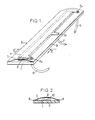
- FIGS. 1 to 3 showing the structure of the sensor according to the invention, as well as to FIGS. 4 and 5 illustrating this sensor in operation.
- the flexible substrate 3 is concave opposite the rigid substrate 1, its concavity being caused for example by the deposition of the conductive plastic on it.
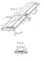
- the two substrates 1 and 3 are joined together along their lateral edges 8 and 9, while they are spaced apart in their elongated middle zone, a space 10 normally existing (as visible in FIG. 2 in particular) between the collector 2 and track 4.
- FIGS. 4 and 5 it can be seen that when pressure is exerted, for example by means of a human finger 11, on the flexible substrate 3, in a determined zone 12 thereof, the track 4 comes into contact, in this zone 12, with the collector 2, as visible in particular in FIG. 5. At the level of zone 12, the track 4 is in mechanical and electrical contact with the collector 2.
- the device of FIGS. 1 to 3 makes it possible to perform a function equivalent to that of a potentiometer, the pressure of the finger filling the role of the cursor of a classic potentiometer.
- rectangle X we find - schematically the resistive track 4 and the conductive collector 2, as well as the electrical conductors 5, 6 and 7 with their respective first ends 5a, 6a and 7a.
- the resistive track 4 can be either linear or functional. Furthermore, it can include intermediate sockets, a midpoint and / or at least one heel resistance (as will be illustrated below) to perform additional functions.
- measurements of the ratiometric type are generally carried out by determining the ratio , by calling VA, V B , V c the potentials at points A, B, C respectively (see FIG. 6), that is to say at the second ends of the conductors 5, 6 and 7 respectively.
- FIG. 6 is shown - schematically by a block Y the processing electronics comprising three inputs connected to points A, B and C and a digital output S.
- FIG. 7 illustrates the part of FIG. 6 included in rectangle X, but by adding a heel resistor 13 connected in series with the resistive track 4; the end 13a of the heel resistor 13 not connected to the resistive track 4 is connected to the first end of a conductor 14.
- the second ends, not connected to the terminals have been noted Ai, Bi, Ci and Di respectively. elements 4, 2 and 13, conductors 14, 5, 7 and 6 respectively.
- One of the problems posed by the sensor according to the invention is the control of the contact between the track 4 and the collector 2 in the zone 12 - in particular the detection of a good contact between these two elements under the effect of an exerted pressure. on track 4, for example using a finger - to eliminate non-significant measurements when the pressure is not clear.
- a curve d is shown showing the variation of the voltage V B 1 (at point Bi in FIG. 7) as a function of time t, when the assembly of FIG. 7 is supplied between the points A 1 and Di, with a voltage U, and when we observe the voltage V B , with respect to V D1 .
- the horizontal line W represents the good contact threshold, V a1 being less than the threshold W in the event of good contact between the track 4 and the collector 2 (zone c), while V B1 is greater than the threshold W in the event of absence of contact (outside zone c, i.e. to the right and left of it).
- the curve d therefore shows what happens when the finger 11 is pressed on track 4 in zone 12, with passage from non-contact to contact (in the zone of good contact c).
- the variation of the voltage V B1 depends of course on the pressure exerted by the finger, on the surface on which the pressure is exerted (therefore on the zone e of the track 4 short-circuited by the collector 4, zone e illustrated on FIG. 6) and also of the voltage U and of the relationship between the value R of the heel resistance 13 and the resistance P of the track 4.
- V B1 The variation of V B1 is given by the formula
- FIGS. 9 and 10 two assemblies have been illustrated making it possible to detect a good frank contact between the track 4 and the collector 2.
- a comparator 15 is used to detect the variation of V B1 with respect to a bias voltage V E defined by a voltage divider with two resistors 16 and 17 of respective values R 1 and R 2 .
- the comparator 15 will output a validation output signal v when V B1 is greater than V e which in fact corresponds to the threshold voltage W defined in FIG. 8 and which is obtained thanks to the voltage divider 16, 17.
- the absence of the validation signal v means that the contact between track 4 and collector 2 does not exist or is not straightforward and that the measurement must be eliminated.
- an analog multiplexer 16b and an analog / digital (or analog / digital) converter 17b are used to measure V S1 -V to check the good contact between the track 4 and the collector 3. D1 and V C1 -V D i.
- the multiplexer 16b multiplexes the voltages V B1 and V C1 , the output of the multiplexer 16b constituting the main input of the converter 17b which receives the voltages V A1 and V D1 as positive and negative reference voltages respectively.
- the digital output is available in Si and it consists, in the event of frank contact between track 4 and collector 2, by a validation signal vi.
- the sensor according to the invention can not only serve as an attenuator, but can provide various information in the case where the finger is replaced by an element movable relative to the sensor, for example the position, the displacement and / or the speed of this element. mobile (or possibly with your finger). It is also possible to perform control functions with the sensor according to the invention.
- This sensor can operate in different ways, namely incrementally, absolutely, parallel, series, synchronously, etc.
- FIGs 11, 12 and 13 there are illustrated three embodiments of a treatment using the sensor according to the invention as - shown diagrammatically in Figures 6 and 7 (without or with heel resistance).
- the assembly of FIG. 9 has been resumed with a comparator 15 for debiting a validation signal v, in the event of good contact;
- the processing unit proper comprises an analog / digital converter 18 receiving V C1 on its main input and V B1 and V D1 on its positive and negative reference inputs respectively.
- the output S 2 of the converter 18 directly represents the position of the contact between the track 4 and the collector 2 when the output of the comparator 15 outputs the validation signal V.
- the output S 2 is absolute in this arrangement.
- FIG. 12 also repeats FIG. 9 with a comparator 15 debiting a validation signal v, in the event of good contact, and it also includes, like FIG. 11, an analog / digital converter 18 with the same inputs as the converter 18 of Figure 11 for connection to Bi, Ci and Di.
- FIG. 12 differs from that of FIG. 11 in that it comprises a lock or memory 19 for recording the preceding digital value s 3 debited by the converter 18 on its output S 2 .
- a control unit 20 controls the converter 18, the lock 19 and a comparator 21 which receives, on the one hand, the previous digital value S 3 of the lock 19 and, on the other hand, the current digital value S4 of the converter 18.
- an AND gate 22 only outputs on its output 23 if it receives the validation signal v from the comparator 15, a control signal from the unit 20 and a non-equality signal from the equality output 21 a of the comparator 21, and this through a NON gate 24 (alternatively the input of the AND gate 22 connected to the output 21 a may be a muting input, which avoids using a separate NOT gate).
- Each comparison between sa and s 3 commanded by the control unit 20 will provide meaning information on the output 21a a and possibly a pulse on the output 23, if there is good contact and if the two values compared S 4 and s 3 are different.
- This is relative, incremental information, which indicates only a change in position of the finger or other mobile element, without any reference of absolute origin.
- FIG. 13 it represents the implementation of a microprocessor 25 connected to them points A 1 , Bi, C 1 , C2 of a sensor according to the invention with track 2 and collector 4, with a heel resistance 13, the voltage + U being applied between point A 1 and point Di, the latter connected to ground.
- the microprocessor can for example be of the ⁇ PD 7816 (or u.PD 7811) type, eight-bit monocircuit, with incorporated analog / digital converter having a digital output S 4 .
- FIG. 14 implements, like FIG. 13, a microprocessor 25a which can also be of the uPD 7811 or u.PD 7816 type.
- This microprocessor comprises a multiplexer 16a and an analog / digital converter 17a of the same type as the multiplexer 16b and the converter 17b of FIG. 10; the connections of the units 16a and 17a are analogous to the connections of the units 16b and 17b in FIG. 10.
- the microprocessor is designed to also include a correction unit 26 connected to the digital output Sa of the converter 17a, the digital output S 5 of the microprocessor 25a being constituted by a digital signal j.
- W threshold (see FIG. 8 and its description) for deciding a good contact for the value read in G (sufficient pressure of a finger or of a mobile element)
- Vp value read previously by the converter 17a on the mumplexed input H of the multiplexer 16a, namely V C1 -V D1
- the senor according to the invention illustrated in Figures 1 to 3 although of a very simple and inexpensive embodiment, can be used in very different arrangements for constituting an attenuator, and in particular an attenuator touch, or to make devices for determining the position, displacement and / or speed of displacement of a movable element relative to the sensor, for example for a robotics application.
Landscapes
- Physics & Mathematics (AREA)
- General Physics & Mathematics (AREA)
- Measurement Of Length, Angles, Or The Like Using Electric Or Magnetic Means (AREA)
Priority Applications (2)
| Application Number | Priority Date | Filing Date | Title |
|---|---|---|---|
| FR8503061A FR2578321B1 (fr) | 1985-03-01 | 1985-03-01 | Capteur de position et de deplacement, notamment de la position et du deplacement d'un doigt humain, en particulier pour realiser un attenuateur. |
| EP86401840A EP0260365A1 (de) | 1986-08-19 | 1986-08-19 | Positions- und Verstellaufnehmer, besonders für die Position und die Verstellung eines menschlichen Daumens, insbesondere zur Verwirklichung eines Dämpfungsgliedes |
Applications Claiming Priority (1)
| Application Number | Priority Date | Filing Date | Title |
|---|---|---|---|
| EP86401840A EP0260365A1 (de) | 1986-08-19 | 1986-08-19 | Positions- und Verstellaufnehmer, besonders für die Position und die Verstellung eines menschlichen Daumens, insbesondere zur Verwirklichung eines Dämpfungsgliedes |
Publications (1)
| Publication Number | Publication Date |
|---|---|
| EP0260365A1 true EP0260365A1 (de) | 1988-03-23 |
Family
ID=8196334
Family Applications (1)
| Application Number | Title | Priority Date | Filing Date |
|---|---|---|---|
| EP86401840A Ceased EP0260365A1 (de) | 1985-03-01 | 1986-08-19 | Positions- und Verstellaufnehmer, besonders für die Position und die Verstellung eines menschlichen Daumens, insbesondere zur Verwirklichung eines Dämpfungsgliedes |
Country Status (1)
| Country | Link |
|---|---|
| EP (1) | EP0260365A1 (de) |
Cited By (2)
| Publication number | Priority date | Publication date | Assignee | Title |
|---|---|---|---|---|
| EP0455838B1 (de) * | 1990-02-09 | 1992-07-08 | Oerlikon-Contraves AG | Schnelleinweisvorrichtung an einem Beobachtungs- und/oder Geschützfahrzeug |
| EP0523343A1 (de) * | 1991-05-23 | 1993-01-20 | Ivac Corporation | Antriebseinrichtung für einen Spritzenkolben einschliesslich Positionsdetektor und Alarmschalter |
Citations (4)
| Publication number | Priority date | Publication date | Assignee | Title |
|---|---|---|---|---|
| DE2517769A1 (de) * | 1975-04-18 | 1976-10-28 | Stephen Hanson Lampen | Spannungsteiler |
| GB1554094A (en) * | 1978-04-18 | 1979-10-17 | Standard Telephones Cables Ltd | Potentiometer arrangement |
| US4270171A (en) * | 1979-03-07 | 1981-05-26 | Maples James A | Position sensing and indicating device |
| US4494105A (en) * | 1982-03-26 | 1985-01-15 | Spectra-Symbol Corporation | Touch-controlled circuit apparatus for voltage selection |
-
1986
- 1986-08-19 EP EP86401840A patent/EP0260365A1/de not_active Ceased
Patent Citations (4)
| Publication number | Priority date | Publication date | Assignee | Title |
|---|---|---|---|---|
| DE2517769A1 (de) * | 1975-04-18 | 1976-10-28 | Stephen Hanson Lampen | Spannungsteiler |
| GB1554094A (en) * | 1978-04-18 | 1979-10-17 | Standard Telephones Cables Ltd | Potentiometer arrangement |
| US4270171A (en) * | 1979-03-07 | 1981-05-26 | Maples James A | Position sensing and indicating device |
| US4494105A (en) * | 1982-03-26 | 1985-01-15 | Spectra-Symbol Corporation | Touch-controlled circuit apparatus for voltage selection |
Non-Patent Citations (1)
| Title |
|---|
| ELECTRONIC DESIGN, vol. 19, 16 septembre 1982, pages 71-82, Waseca, MN, Denville, New Jersey, US; F. GOODENOUGH: "Analog 1/0 boards unburden host muP, system designer, and ultimate user" * |
Cited By (3)
| Publication number | Priority date | Publication date | Assignee | Title |
|---|---|---|---|---|
| EP0455838B1 (de) * | 1990-02-09 | 1992-07-08 | Oerlikon-Contraves AG | Schnelleinweisvorrichtung an einem Beobachtungs- und/oder Geschützfahrzeug |
| US5151677A (en) * | 1990-02-09 | 1992-09-29 | Oerlikon-Contraves Ag | Rapid orientation apparatus for an observation and/or weapon-carrying vehicle |
| EP0523343A1 (de) * | 1991-05-23 | 1993-01-20 | Ivac Corporation | Antriebseinrichtung für einen Spritzenkolben einschliesslich Positionsdetektor und Alarmschalter |
Similar Documents
| Publication | Publication Date | Title |
|---|---|---|
| EP0739460B1 (de) | Scheibenbremse mit erhöhter sicherheit | |
| EP0866958B1 (de) | Wheatstone-brücke mit temperaturgradientenkompensation | |
| EP0612982B2 (de) | Messschaltung für Widerstandssensor, insbesondere Krafstoffmesser | |
| EP0510061B1 (de) | Vorrichtung zur messung der änderung der kapazität eines kondensators, insbesondere eines sensors | |
| FR2802302A1 (fr) | Appareil de mesure de l'intensite du courant dans un conducteur | |
| CA1126852A (fr) | Dispositif de traitement d'un signal d'analyse d'image | |
| EP0068949A1 (de) | Verfahren zur optischen Analog-/Digitalumwandlung und entsprechender Wandler | |
| EP0546907B1 (de) | Winkelposition-Sensor mit fortlaufender geschlossener Widerstandsspur und Messverfahren dafür | |
| WO2013001081A1 (fr) | Dispositif resisitif a jauge de contrainte a nanofils de silicium et procede d'optimisation de la consommation electrique d'un tel dispositif | |
| WO2012156016A1 (fr) | Mesure differentielle de tension | |
| EP0990128B1 (de) | Druckwandler mit kompensation der nichtlinearität der nulldrift für tiefe temperaturen | |
| FR2511535A1 (fr) | Tete de transducteur magnetique | |
| FR2743631A1 (fr) | Detecteur de pression ou de force s'exercant de l'exterieur | |
| CH629632A5 (fr) | Dispositif de controle automatique du gain d'une voie de reception d'une installation de transmission comportant des liaisons optiques. | |
| EP0065901B1 (de) | Potentiometermesswertumformersystem | |
| EP0260365A1 (de) | Positions- und Verstellaufnehmer, besonders für die Position und die Verstellung eines menschlichen Daumens, insbesondere zur Verwirklichung eines Dämpfungsgliedes | |
| FR2578321A1 (fr) | Capteur de position et de deplacement, notamment de la position et du deplacement d'un doigt humain, en particulier pour realiser un attenuateur. | |
| FR2550671A1 (fr) | Circuit convertisseur analogique-numerique et demodulateur de signaux video modules en argument | |
| CH675487A5 (de) | ||
| FR2549232A1 (fr) | Perfectionnements aux dispositifs pour lire les quantites de charges electriques portees par un dielectrique | |
| FR2670342A1 (fr) | Dispositif de detection du pincement et/ou de la coupure d'un joint resistif. | |
| FR2925668A1 (fr) | Procede de correction de gain d'un organe capacitif et dispositif de mise en oeuvre | |
| EP0796421B1 (de) | Filtervorrichtung, insbesondere für die kraftstoffanzeige in automobilen | |
| EP0369868A1 (de) | Messgerät für die gleichzeitige Messung von wenigstens zwei elektrischen Grössen | |
| EP0269531A1 (de) | Vorrichtung zur Feststellung der Beschaffenheit von Fleisch |
Legal Events
| Date | Code | Title | Description |
|---|---|---|---|
| PUAI | Public reference made under article 153(3) epc to a published international application that has entered the european phase |
Free format text: ORIGINAL CODE: 0009012 |
|
| AK | Designated contracting states |
Kind code of ref document: A1 Designated state(s): AT BE CH DE GB IT LI LU NL SE |
|
| 17P | Request for examination filed |
Effective date: 19880902 |
|
| 17Q | First examination report despatched |
Effective date: 19900802 |
|
| RAP1 | Party data changed (applicant data changed or rights of an application transferred) |
Owner name: M C B |
|
| STAA | Information on the status of an ep patent application or granted ep patent |
Free format text: STATUS: THE APPLICATION HAS BEEN REFUSED |
|
| 18R | Application refused |
Effective date: 19910810 |
|
| RIN1 | Information on inventor provided before grant (corrected) |
Inventor name: TAILLEBOIS, JACQUES Inventor name: HOUARD, PHILIPPE Inventor name: MARCHAND, VERONIQUE Inventor name: CAULLET, ALAIN |