EP0260367A1 - Kälteanlage - Google Patents
Kälteanlage Download PDFInfo
- Publication number
- EP0260367A1 EP0260367A1 EP86730138A EP86730138A EP0260367A1 EP 0260367 A1 EP0260367 A1 EP 0260367A1 EP 86730138 A EP86730138 A EP 86730138A EP 86730138 A EP86730138 A EP 86730138A EP 0260367 A1 EP0260367 A1 EP 0260367A1
- Authority
- EP
- European Patent Office
- Prior art keywords
- refrigerant
- condenser
- evaporator
- low
- liquid separator
- Prior art date
- Legal status (The legal status is an assumption and is not a legal conclusion. Google has not performed a legal analysis and makes no representation as to the accuracy of the status listed.)
- Granted
Links
Images

Classifications
-
- F—MECHANICAL ENGINEERING; LIGHTING; HEATING; WEAPONS; BLASTING
- F25—REFRIGERATION OR COOLING; COMBINED HEATING AND REFRIGERATION SYSTEMS; HEAT PUMP SYSTEMS; MANUFACTURE OR STORAGE OF ICE; LIQUEFACTION SOLIDIFICATION OF GASES
- F25D—REFRIGERATORS; COLD ROOMS; ICE-BOXES; COOLING OR FREEZING APPARATUS NOT OTHERWISE PROVIDED FOR
- F25D16/00—Devices using a combination of a cooling mode associated with refrigerating machinery with a cooling mode not associated with refrigerating machinery
-
- F—MECHANICAL ENGINEERING; LIGHTING; HEATING; WEAPONS; BLASTING
- F25—REFRIGERATION OR COOLING; COMBINED HEATING AND REFRIGERATION SYSTEMS; HEAT PUMP SYSTEMS; MANUFACTURE OR STORAGE OF ICE; LIQUEFACTION SOLIDIFICATION OF GASES
- F25B—REFRIGERATION MACHINES, PLANTS OR SYSTEMS; COMBINED HEATING AND REFRIGERATION SYSTEMS; HEAT PUMP SYSTEMS
- F25B41/00—Fluid-circulation arrangements
-
- F—MECHANICAL ENGINEERING; LIGHTING; HEATING; WEAPONS; BLASTING
- F25—REFRIGERATION OR COOLING; COMBINED HEATING AND REFRIGERATION SYSTEMS; HEAT PUMP SYSTEMS; MANUFACTURE OR STORAGE OF ICE; LIQUEFACTION SOLIDIFICATION OF GASES
- F25B—REFRIGERATION MACHINES, PLANTS OR SYSTEMS; COMBINED HEATING AND REFRIGERATION SYSTEMS; HEAT PUMP SYSTEMS
- F25B2400/00—Component parts or details not otherwise provided for in this subclass
- F25B2400/23—Separators
Definitions
- the invention relates to a refrigeration system according to the preamble of claim 1.
- the known compression systems work in such a way that a vaporous but easily liquefiable refrigerant is first compressed in a compressor and then liquefied in a condenser with a coolant whose temperature is lower than the condensation temperature of the refrigerant at the present pressure.
- the compression circuit with the compressor, the condenser and the pressure-reducing member is led out of the gas collecting space of the separator and flows back into it, while the low-pressure circuit containing the flooded evaporator removes the refrigerant from the liquid collecting area of the separator and this in part gaseous, partly liquid state into the gas collector area returns.
- the compressor consumes a relatively large amount of energy and, in addition, the compressor and the corresponding energy supply lines have to be designed for a high connected load, as a result of which the operating and connection costs are considerable.
- the invention is characterized in that a condenser is inserted behind the evaporator in the low-pressure circuit in the flow direction of the refrigerant.
- a condenser is inserted behind the evaporator in the low-pressure circuit in the flow direction of the refrigerant.
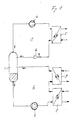
- a compression circuit 1 and a low-pressure circuit 2 for a conventional refrigerant are connected to one another by a liquid separator 3.
- the liquid phase of the refrigerant collects in the lower area, while the upper area is filled with the gas phase of the refrigerant.
- the boundary between the liquid phase and the gas phase is selected such that the two connections of the compression circuit 1 open into the gas collection area, while the line through which the refrigerant is fed to the low-pressure circuit 2 always leads to the liquid collection area, and the line via which the refrigerant is returned from the low-pressure circuit 2 into the liquid separator 3, with the gas collection area of which are connected.
- the compression circuit 1 is designed in a known manner and points in the direction of flow of the refrigerant arranged one behind the other a compressor 4, a condenser 5 and a pressure reducing member in the form of an HP float valve 6.
- the compressor 4 is supplied with gaseous refrigerant from the liquid separator 3, which is compressed by the latter.
- the condenser 5 the compressed refrigerant is condensed by a supplied coolant through heat exchange and then the pressure of the liquid refrigerant in the float valve 6 is reduced to the pressure prevailing in the liquid separator 3.
- the liquid refrigerant flows from the float valve 6 into the liquid separator 3 and collects in the lower area.
- the low-pressure circuit 2 which is fed from the liquid collection area of the liquid separator 3, there are a refrigerant pump 7, an evaporator 8 and a condenser 9 arranged one behind the other in the direction of flow of the refrigerant
- Liquid refrigerant is evaporated to the extent necessary to adequately cool the medium to be cooled, which is also supplied to the evaporator 8.
- the fully or partially evaporated refrigerant passes from the evaporator 8 into the condenser 9, where it is partially or completely liquefied again.
- a medium which is available in sufficient quantity and inexpensively is preferably used as the coolant for condensation of the refrigerant in the condenser 9.
- Preferred media are the outside air or ice or water of an ice store.
- the refrigerant discharged from the condenser 9 to the liquid separator 3 is thus at least partially liquefied.
- the remaining gas phase collects in the upper area of the liquid separator 3 and is taken up by the compression circuit 1 and liquefied in it.
- the condenser 9 has the effect that the amount of gaseous refrigerant still to be liquefied in the compression circuit 1 is relatively small.
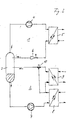
- the refrigeration system according to FIG. 1 is modified so that a three-way valve 10 is inserted into the refrigerant line between the condenser 9 and the liquid separator 3, which valve is additionally connected to the refrigerant outlet of the evaporator 8.
- the three-way valve 10 can be set so that it only connects the output of the condenser 9 in its first switching state and only the output of the evaporator 8 to the liquid separator 3 in its second switching state. In the first switching state, the system thus corresponds to that in FIG. 1, ie evaporator 8 and condenser 9 are connected in series in the refrigerant circuit.
- the condenser 9 In the second switching state, the condenser 9 is bridged by the line leading from the outlet of the evaporator 8 to the three-way valve 10. Since the connection between the output of the capacitor 9 and the Liquid separator 3 is interrupted by the three-way valve 10, the condenser 9 is thus completely removed from the low-pressure refrigerant circuit.
- This second switching state will be selected when the temperature of the coolant supplied to the condenser 9 is higher than that of the refrigerant leaving the evaporator 8. In this case, with the condenser 9 switched on, it would also act as an evaporator and cool the coolant, as a result of which the work to be performed by the compressor 4 would not only not be reduced, but would even be increased.
- the temperature of the coolant for the condenser 9 fluctuates greatly, for example when the outside air is used as the coolant. If the temperature of the outside air exceeds a certain value dependent on the temperature of the refrigerant, for example 25 ° C or 30 ° C, then the three-way valve 10 is switched to the second switching state, so that the condenser 9 is removed from the low-pressure circuit 2 and the Compressor 4 not loaded. If the temperature of the outside air falls below the mentioned value again, the condenser 9 is switched on again and relieves the load on the compressor 4.
- FIG. 3 there is a three-way valve 11 in the refrigerant line between the outlet of the evaporator 8 and the inlet of the condenser 9, which valve is additionally connected directly to the outlet of the refrigerant pump 7.
- the three-way valve 11 can be switched so that it has the output of the evaporator 8 connects to the input of the condenser 9 and interrupts the line between the pump 7 and the condenser 9 (first switching state), ie the system works like that shown in FIG. 1 or so that the line between the evaporator 8 and the condenser 9 interrupted and which is released between the pump 7 and the condenser 9 (second switching state).
- the evaporator 8 In the second switching state, the evaporator 8 is thus removed from the low-pressure circuit 2, as a result of which the condenser 9 takes up the power of the compressor 4 and acts as an evaporator, so that the coolant fed to the condenser 9, cooled and circulated, is cooled and in a reservoir, for example a Ice storage.
- the evaporator 8 In the first switching state of the three-way valve 11, the evaporator 8 is switched on again to cool a medium and the condenser 9 acts to condense the refrigerant, the coolant stored in the reservoir being heated again. 3 is particularly useful if the cooling effect of the evaporator 8 is only needed temporarily.
- the coolant for the condenser 9 is advantageously cooled via the second switching state of the three-way valve 11 when the costs for the energy supplied to the compressor 4 are staggered according to time tariffs and there is a low tariff.
- the first switching state of the three-way valve 11 is then set, as a result of which the evaporator 8 is effective and the refrigerant in the condenser 9 is condensed by heat exchange with the coolant, ie discharge of the cold reservoir.
- the compressor 4 then runs at a much lower output than is actually required for cooling the medium in the evaporator 8, or can even be switched off completely, so that electrical energy is only required for the pump 7. In the subsequent low tariff period, the cold reservoir is recharged via the condenser 9.
- the system according to FIG. 3 can also be used to bring about constant utilization of the compressor 4, so that the power that is only temporarily required by the evaporator 8 can be a multiple of the power constantly supplied by the compressor 4.
- the compressor can therefore be made particularly small.
Landscapes
- Engineering & Computer Science (AREA)
- Physics & Mathematics (AREA)
- Mechanical Engineering (AREA)
- Thermal Sciences (AREA)
- General Engineering & Computer Science (AREA)
- Chemical & Material Sciences (AREA)
- Combustion & Propulsion (AREA)
- Compression-Type Refrigeration Machines With Reversible Cycles (AREA)
- Organic Low-Molecular-Weight Compounds And Preparation Thereof (AREA)
Abstract
Description
- Die Erfindung betrifft eine Kälteanlage gemäß dem Oberbegriff des Anspruchs 1.
- Die bekannten Kompressionsanlagen arbeiten in der Weise, daß ein dampfförmiges, aber leicht zu verflüssigendes Kältemittel zunächst in einem Verdichter komprimiert und dann in einem Kondensator mit einem Kühlmittel verflüssigt wird, dessen Temperatur niedriger liegt als die Kondensationstemperatur des Kältemittels bei dem vorliegenden Druck. Der Kompressionskreislauf mit dem Verdichter, dem Kondensator und dem Druckreduktionsglied wird aus dem Gassammelraum des Abscheiders herausgeführt und mündet wieder in diesen, während der den überfluteten Verdampfer enthaltende Niederdruckkreislauf das Kältemittel aus dem Flüssigkeitssammelbereich des Abscheiders entnimmt und dieses in teils gasförmigem, teilsflüssigem Zustand in den Gassammel bereich zurückführt. Bei dieser bekannten Kälteanlage verbraucht der Verdichter relativ viel Energie und außerdem müssen der Verdichter und die entsprechenden Energiezuführungsleitungen für eine hohe Anschlußleistung ausgelegt sein, wodurch die Betriebs- und Anschlußkosten erheblich sind.
- Es ist daher die Aufgabe der vorliegenden Erfindung, die vorbeschriebene, bekannte Kompressionskälteanlage in der Weise weiterzuentwickeln, daß bei gleicher Kühlwirkung der Energieverbrauch und Anschlußleistung des Verdichters herabgesetzt werden können.
- Diese Aufgabe wird erfindungsgemäß gelöst durch das im kennzeichnenden Teil des Anspruchs 1 angegebene Merkmal. Vorteilhafte Weiterbildungen der erfindungsgemäßen Kälteanlage ergeben sich aus den Unteransprüchen.
- Die Erfindung zeichnet sich dadurch aus, daß in den Niederdruckkreislauf in Flußrichtung des Kältemittels hinter dem Verdampfer ein Kondensator eingefügt ist. Durch diese Maßnahme erfolgt bereits im Niederdruckkreislauf hinter dem Verdampfer eine teilweise oder sogar vollständige Kondensation des Kältemittels. Hierdurch wird der Anteil des im Kompressionskreislauf zu verflüssigenden Kältemittels herabgesetzt, wodurch auch die vom Verdichter zu leistende Arbeit entsprechend verringert wird. Bei unveränderter Betriebszeit des Verdichters hat dies auch eine Verminderung der Verdichterleistung zur Folge, so daß der Verdichter entsprechend kleiner gehalten werden kann.
- Die Erfindung wird im folgenden anhand von in den Figuren dargestellten Ausführungsbeispielen näher erläutert. Es zeigen:
- Fig. 1 ein Schemabild einer ersten Ausführungsform einer Kompressionskälteanlage,
- Fig. 2 ein Schemabild einer zweiten Ausführungsform einer Kompressionsanglage, und
- Fig. 3 ein Schemabild einer dritten Ausführungsform einer Kompressionskälteanlage.
- Gemäß Fig. 1 sind ein Kompressionskreislauf 1 und ein Niederdruckkreislauf 2 für ein herkömmliches Kältemittel durch einen Flüssigkeitsabscheider 3 miteinander verbunden. Im Flüssigkeitsabscheider 3 sammelt sich die flüssige Phase des Kältemittels im unteren Bereich, während der obere Bereich durch die Gasphase des Kältemittels ausgefüllt ist. Die Grenze zwischen flüssiger Phase und Gasphase ist so gewählt, daß die beiden Anschlüsse des Kompressionskreislaufs 1 in den Gassammelbereich münden, während die Leitung, durch die das Kältemittel dem Niederdruckkreislauf 2 zugeführt wird, stets mit dem Flüssigkeitssammelbereich, und die Leitung, über die das Kältemittel aus dem Niederdruckkreislauf 2 in den Flüssigkeitsabscheider 3 zurückgeführt wird, mit dessen Gassammelbereich verbunden sind.
- Der Kompressionskreislauf 1 ist in bekannter Weise ausgebildet und weist in Fließrichtung des Kältemittels hintereinander angeordnet einen Verdichter 4, einen Kondensator 5 und ein Druckreduktionsglied in Form eines HD-Schwimmerventils 6 auf. Dem Verdichter 4 wird aus dem Flüssigkeitsabscheider 3 gasförmiges Kältemittel zugeführt, das von diesem komprimiert wird. Im Kondensator 5 wird das komprimierte Kältemittel durch ein zugeführtes Kühlmittel durch Wärmetausch kondensiert und anschließend wird der Druck des flüssigen Kältemittels im Schwimmerventil 6 auf den im Flüssigkeitsabscheider 3 herrschenden Druck reduziert. Das flüssige Kältemittel fließt aus dem Schwimmerventil 6 in den Flüssigkeitsabscheider 3 und sammelt sich im unteren Bereich.
- Im Niederdruckkreislauf 2, der aus dem Flüssigkeitssammelbereich des Flüssigkeitsabscheiders 3 gespeist wird, befinden sich in Flußrichtung des Kältemittels hintereinander angeordnet eine Kältemittelpumpe 7, ein Verdampfer 8 sowie ein Kondensator 9. Der Verdampfer 8 arbeitet im überfluteten Betrieb, d.h. das ihm durch die Kältemittelpumpe 7 zugeführte flüssige Kältemittel wird in dem Maße verdampft, wie zur ausreichenden Kühlung des dem Verdampfer 8 ebenfalls zugeführten zu kühlenden Mediums erforderlich ist. Das ganz oder teilweise verdampfte Kältemittel gelangt aus dem Verdampfer 8 in den Kondensator 9, in dem es wieder teilweise oder vollständig verflüssigt wird. Als Kühlmittel für Kondensation des Kältemittels im Kondensator 9 wird vorzugsweise ein Medium verwendet, das in ausreichender Menge und preisgünstig zur Verfügung steht. Bevorzugte Medien sind die Außenluft oder Eis bzw. Wasser eines Eisspeichers.
- Das vom Kondensator 9 an den Flüssigkeitsabscheider 3 abgegebene Kältemittel ist somit zumindest teilweise verflüssigt. Die verbleibende Gasphase sammelt sich im oberen Bereich des Flüssigkeitsabscheiders 3 und wird vom Kompressionskreislauf 1 aufgenommen und in diesem verflüssigt. Jedoch bewirkt der Kondensator 9, daß die im Kompressionskreislauf 1 noch zu verflüssigende gasförmige Kältemittelmenge relativ gering ist.
- Dadurch wird der Kompressionskreislauf wesentlich entlastet, wodurch Energie eingespart wird und die Komponenten des Kompressionskreislaufs 1 entsprechend einfacher ausgebildet sein können.
- Bei der Ausführungsform nach Fig. 2 ist die Kälteanlage nach Fig. 1 so modifiziert, daß in die Kältemittelleitung zwischen dem Kondensator 9 und dem Flüssigkeitsabscheider 3 ein Dreiwegeventil 10 eingesetzt ist, das zusätzlich mit dem Kältemittelausgang des Verdampfers 8 verbunden ist. Das Dreiwegeventil 10 kann so eingestellt werden, daß es in seinem ersten Schaltzustand nur den Ausgang des Kondensators 9 und in seinem zweiten Schaltzustand nur den Ausgang des Verdampfers 8 mit dem Flüssigkeitsabscheider 3 verbindet. Im ersten Schaltzustand entspricht die Anlage somit der in Fig. 1, d.h. Verdampfer 8 und Kondensator 9 sind im Kältemittelkreislauf hintereinandergeschaltet. Im zweiten Schaltzustand wird der Kondensator 9 durch die vom Ausgang des Verdampfers 8 zum Dreiwegeventil 10 führenden Leitung überbrückt. Da die Verbindung zwischen dem Ausgang des Kondensators 9 und dem Flüssigkeitsabscheider 3 durch das Dreiwegeventil 10 unterbrochen ist, ist somit der Kondensator 9 vollständig aus Kältemittel-Niederdruckkreislauf herausgenommen. Diesen zweiten Schaltzustand wird man wählen, wenn die Temperatur des dem Kondensator 9 zugeführten Kühlmittels höher ist als die des den Verdampfer 8 verlassenden Kältemittels. In diesem Fall würde bei eingeschaltetem Kondensator 9 dieser ebenfalls als Verdampfer wirken und das Kühlmittel kühlen, wodurch die vom Verdichter 4 zu leistende Arbeit nicht nur nicht verringert, sondern sogar noch erhöht würde. Die Kälteanlage nach Fig. 2 wird man somit wählen, wenn die Temperatur des Kühlmittels für den Kondensator 9 stark schwankt, z.B. bei Verwendung der Außenluft als Kühlmittel. Übersteigt die Temperatur der Außenluft einen bestimmten, von der Temperatur des Kältemittels abhängigen Wert, beispielsweise 25° C oder 30° C, dann erfolgt eine Umschaltung des Dreiwegeventils 10 in den zweiten Schaltzustand, so daß der Kondensator 9 aus dem Niederdruckkreislauf 2 herausgenommen wird und der Verdichter 4 nicht belastet. Fällt die Temperatur der Außenluft wieder unter den genannten Wert, wird der Kondensator 9 wieder zugeschaltet und entlastet den Verdichter 4.
- Bei der Ausführungsform nach Fig. 3 befindet sich in der Kältemittelleitung zwischen dem Ausgang des Verdampfers 8 und dem Eingang des Kondensators 9 ein Dreiwegeventil 11, das zusätzlich direkt mit dem Ausgang der Kältemittelpumpe 7 verbunden ist. Das Dreiwegeventil 11 kann so geschaltet werden, daß es den Ausgang des Verdampfers 8 mit dem Eingang des Kondensators 9 verbindet und die Leitung zwischen Pumpe 7 und Kondensator 9 unterbricht (erster Schaltzustand), d.h. die Anlage arbeitet wie die in Fig. 1 gezeigte, oder so, daß die Leitung zwischen dem Verdampfer 8 und dem Kondensator 9 unterbrochen und die zwischen der Pumpe 7 und dem Kondensator 9 freigegeben ist (zweiter Schaltzustand). Im zweiten Schaltzustand ist somit der Verdampfer 8 aus dem Niederdruckkreislauf 2 herausgenommen, wodurch der Kondensator 9 die Leistung des Verdichters 4 aufnimmt und als Verdampfer wirkt, so daß das dem Kondensator 9 zugeleitete, in einem Kreislauf geführte Kühlmittel abgekühlt und in einem Reservoir, z.B. einem Eisspeicher, gelagert wird. Im ersten Schaltzustand des Dreiwegeventils 11 ist der Verdampfer 8 wieder zur Kühlung eines Mediums eingeschaltet und der Kondensator 9 wirkt zur Kondensation des Kältemittels, wobei das im Reservoir gespeicherte Kühlmittel wieder erwärmt wird. Die Anlage nach Fig. 3 ist insbesondere dann sinnvoll, wenn die Kühlwirkung des Verdampfers 8 nur zeitweise benötigt wird. Das Kühlmittel für den Kondensator 9 wird über den zweiten Schaltzustand des Dreiwegeventils 11 vorteilhaft dann gekühlt, wenn die Kosten für die den Verdichter 4 zugeführte Energie nach Zeittarifen gestaffelt sind und ein niedriger Tarif besteht. Zu den Hochtarifzeiten wird dann der erste Schaltzustand des Dreiwegeventils 11 eingestellt, wodurch der Verdampfer 8 wirksam ist und eine Kondensation des Kältemittels im Kondensator 9 durch Wärmetausch mit dem Kühlmittel, d.h. Entladung des Kältereservoirs, erfolgt.
- Der Verdichter 4 Läuft dann mit wesentlich geringerer Leistung, als zur Kühlung des Mediums im Verdampfer 8 tatsächlich erforderlich ist, oder kann sogar ganz abgeschaltet werden, so daß nur für die Pumpe 7 elektrische Energie benötigt wird. In der nachfolgenden Niedertarifzeit wird das Kältereservoir über den Kondensator 9 wieder geladen.
- Die Anlage nach Fig. 3 kann auch dazu dienen, eine konstante Auslastung des Verdichters 4 herbeizuführen, so daß die jeweils nur zeitweilig vom Verdampfer 8 benötigte Leistung ein Vielfaches der vom Verdichter 4 ständig gelieferten Leistung betragen kann. Der Verdichter kann daher besonders klein ausgebildet sein.
Claims (5)
dadurch gekennseichnet,
daß in den Niederdruckkreislauf (2) in Flußrichtung des Kältemittels hinter dem Verdampfer (8) ein Kondensator (9) eingefügt ist.
Priority Applications (3)
| Application Number | Priority Date | Filing Date | Title |
|---|---|---|---|
| DE8686730138T DE3669916D1 (de) | 1986-09-16 | 1986-09-16 | Kaelteanlage. |
| AT86730138T ATE51440T1 (de) | 1986-09-16 | 1986-09-16 | Kaelteanlage. |
| EP86730138A EP0260367B1 (de) | 1986-09-16 | 1986-09-16 | Kälteanlage |
Applications Claiming Priority (1)
| Application Number | Priority Date | Filing Date | Title |
|---|---|---|---|
| EP86730138A EP0260367B1 (de) | 1986-09-16 | 1986-09-16 | Kälteanlage |
Publications (2)
| Publication Number | Publication Date |
|---|---|
| EP0260367A1 true EP0260367A1 (de) | 1988-03-23 |
| EP0260367B1 EP0260367B1 (de) | 1990-03-28 |
Family
ID=8196443
Family Applications (1)
| Application Number | Title | Priority Date | Filing Date |
|---|---|---|---|
| EP86730138A Expired - Lifetime EP0260367B1 (de) | 1986-09-16 | 1986-09-16 | Kälteanlage |
Country Status (3)
| Country | Link |
|---|---|
| EP (1) | EP0260367B1 (de) |
| AT (1) | ATE51440T1 (de) |
| DE (1) | DE3669916D1 (de) |
Cited By (6)
| Publication number | Priority date | Publication date | Assignee | Title |
|---|---|---|---|---|
| EP0543194A3 (en) * | 1991-11-20 | 1993-08-04 | Air Products And Chemicals, Inc. | Refrigeration apparatus and method of refrigeration |
| EP0595724A1 (de) * | 1992-10-30 | 1994-05-04 | Jf Cesbron S.A. | Anlage für die Produktion und Ausgabe von Kälte |
| EP1798498A3 (de) * | 2005-12-13 | 2008-07-09 | Sanden Corporation | Dampfkompressionssystem |
| EP1855068A3 (de) * | 2006-05-10 | 2008-11-05 | Sanden Corporation | Dampfkompressionskühlkreislauf |
| EP3159626A1 (de) * | 2015-10-20 | 2017-04-26 | Ulrich Brunner GmbH | Wärmepumpenkreislauf |
| CN109114842A (zh) * | 2018-09-27 | 2019-01-01 | 克莱门特捷联制冷设备(上海)有限公司 | 一种耦合型机房空调系统及其控制方法 |
Citations (3)
| Publication number | Priority date | Publication date | Assignee | Title |
|---|---|---|---|---|
| US2096065A (en) * | 1932-03-23 | 1937-10-19 | Ruppricht Siegfried | Refrigerating system |
| FR2341109A1 (fr) * | 1976-02-13 | 1977-09-09 | Doomernik Cornelis | Accumulateur de froid |
| FR2544470A1 (fr) * | 1982-12-10 | 1984-10-19 | Hiross Int Co | Unite de refroidissement pour fluides dans une installation de conditionnement d'air |
-
1986
- 1986-09-16 DE DE8686730138T patent/DE3669916D1/de not_active Expired - Fee Related
- 1986-09-16 AT AT86730138T patent/ATE51440T1/de not_active IP Right Cessation
- 1986-09-16 EP EP86730138A patent/EP0260367B1/de not_active Expired - Lifetime
Patent Citations (3)
| Publication number | Priority date | Publication date | Assignee | Title |
|---|---|---|---|---|
| US2096065A (en) * | 1932-03-23 | 1937-10-19 | Ruppricht Siegfried | Refrigerating system |
| FR2341109A1 (fr) * | 1976-02-13 | 1977-09-09 | Doomernik Cornelis | Accumulateur de froid |
| FR2544470A1 (fr) * | 1982-12-10 | 1984-10-19 | Hiross Int Co | Unite de refroidissement pour fluides dans une installation de conditionnement d'air |
Cited By (7)
| Publication number | Priority date | Publication date | Assignee | Title |
|---|---|---|---|---|
| EP0543194A3 (en) * | 1991-11-20 | 1993-08-04 | Air Products And Chemicals, Inc. | Refrigeration apparatus and method of refrigeration |
| EP0595724A1 (de) * | 1992-10-30 | 1994-05-04 | Jf Cesbron S.A. | Anlage für die Produktion und Ausgabe von Kälte |
| FR2697619A1 (fr) * | 1992-10-30 | 1994-05-06 | Cesbron Jf | Installation de production et de distribution de froid d'un nouveau type. |
| EP1798498A3 (de) * | 2005-12-13 | 2008-07-09 | Sanden Corporation | Dampfkompressionssystem |
| EP1855068A3 (de) * | 2006-05-10 | 2008-11-05 | Sanden Corporation | Dampfkompressionskühlkreislauf |
| EP3159626A1 (de) * | 2015-10-20 | 2017-04-26 | Ulrich Brunner GmbH | Wärmepumpenkreislauf |
| CN109114842A (zh) * | 2018-09-27 | 2019-01-01 | 克莱门特捷联制冷设备(上海)有限公司 | 一种耦合型机房空调系统及其控制方法 |
Also Published As
| Publication number | Publication date |
|---|---|
| DE3669916D1 (de) | 1990-05-03 |
| ATE51440T1 (de) | 1990-04-15 |
| EP0260367B1 (de) | 1990-03-28 |
Similar Documents
| Publication | Publication Date | Title |
|---|---|---|
| DE3220335C2 (de) | Wärmepumpensystem mit einer Kältemittelmischung | |
| EP0333632B1 (de) | Anlage zur Verdichtung von Wasserstoffgas | |
| DE3805987C2 (de) | ||
| DE4019669C2 (de) | Adsorptionsthermischer Speicher | |
| DE3875006T2 (de) | Waermepumpensystem. | |
| DE69004009T2 (de) | Kühlanlage mit Zusatzwärmespeicher. | |
| DE69513765T2 (de) | Kälteanlage | |
| DE60218793T2 (de) | Kältemittelkreislauf | |
| DE68926966T2 (de) | Wärmepumpengerät | |
| EP2447096A1 (de) | Wärmepumpeneinrichtung mit Enteisungsfunktion | |
| EP0260367A1 (de) | Kälteanlage | |
| DE102008043807A1 (de) | Kälteanlage | |
| EP0593495B1 (de) | Kühlvorrichtung | |
| EP2215412A1 (de) | Anlage für die kälte-, heiz- oder klimatechnik, insbesondere kälteanlagen | |
| DE2758547A1 (de) | Verfahren zur verbesserung der energiebilanz von absorptionskaelteanlagen | |
| DE112017005948T5 (de) | Klimatisierungsvorrichtung | |
| DE102014000571A1 (de) | Brennstoffzellensystem | |
| EP0239837A2 (de) | Verfahren zur Rückgewinnung von Verflüssigungswärme einer Kälteanlage und Kälteanlage zur Durchführung des Verfahrens | |
| EP0152608B1 (de) | Verfahren zur Steuerung einer Verbundkälteanlage | |
| EP2473795A2 (de) | Wärmepumpe | |
| DE8625036U1 (de) | Kühlvorrichtung | |
| DE8712812U1 (de) | Drucklufttrockner | |
| DE10318655B3 (de) | Klimatisierungssystem für ein Kraftfahrzeug und Verfahren zum Betreiben desselben | |
| DE19832682C2 (de) | Abtaueinrichtung für einen Verdampfer einer Wärmepumpe oder eines Klimageräts | |
| DE2719995A1 (de) | Absorptionskaelteanlage |
Legal Events
| Date | Code | Title | Description |
|---|---|---|---|
| PUAI | Public reference made under article 153(3) epc to a published international application that has entered the european phase |
Free format text: ORIGINAL CODE: 0009012 |
|
| AK | Designated contracting states |
Kind code of ref document: A1 Designated state(s): AT BE CH DE FR GB IT LI LU NL SE |
|
| 17P | Request for examination filed |
Effective date: 19880303 |
|
| 17Q | First examination report despatched |
Effective date: 19881020 |
|
| GRAA | (expected) grant |
Free format text: ORIGINAL CODE: 0009210 |
|
| AK | Designated contracting states |
Kind code of ref document: B1 Designated state(s): AT BE CH DE FR GB IT LI LU NL SE |
|
| REF | Corresponds to: |
Ref document number: 51440 Country of ref document: AT Date of ref document: 19900415 Kind code of ref document: T |
|
| REF | Corresponds to: |
Ref document number: 3669916 Country of ref document: DE Date of ref document: 19900503 |
|
| GBT | Gb: translation of ep patent filed (gb section 77(6)(a)/1977) | ||
| ET | Fr: translation filed | ||
| ITF | It: translation for a ep patent filed | ||
| RAP2 | Party data changed (patent owner data changed or rights of a patent transferred) |
Owner name: SMENTEK, ANNEMARIE |
|
| NLT2 | Nl: modifications (of names), taken from the european patent patent bulletin |
Owner name: ANNEMARIE SMENTEK TE BERLIJN, BONDSREPUBLIEK DUITS |
|
| PLBE | No opposition filed within time limit |
Free format text: ORIGINAL CODE: 0009261 |
|
| STAA | Information on the status of an ep patent application or granted ep patent |
Free format text: STATUS: NO OPPOSITION FILED WITHIN TIME LIMIT |
|
| 26N | No opposition filed | ||
| PGFP | Annual fee paid to national office [announced via postgrant information from national office to epo] |
Ref country code: GB Payment date: 19930901 Year of fee payment: 8 |
|
| PGFP | Annual fee paid to national office [announced via postgrant information from national office to epo] |
Ref country code: BE Payment date: 19930914 Year of fee payment: 8 |
|
| PGFP | Annual fee paid to national office [announced via postgrant information from national office to epo] |
Ref country code: LU Payment date: 19930915 Year of fee payment: 8 |
|
| PGFP | Annual fee paid to national office [announced via postgrant information from national office to epo] |
Ref country code: SE Payment date: 19930916 Year of fee payment: 8 Ref country code: FR Payment date: 19930916 Year of fee payment: 8 |
|
| PGFP | Annual fee paid to national office [announced via postgrant information from national office to epo] |
Ref country code: AT Payment date: 19930924 Year of fee payment: 8 |
|
| ITTA | It: last paid annual fee | ||
| PGFP | Annual fee paid to national office [announced via postgrant information from national office to epo] |
Ref country code: NL Payment date: 19930930 Year of fee payment: 8 Ref country code: CH Payment date: 19930930 Year of fee payment: 8 |
|
| PGFP | Annual fee paid to national office [announced via postgrant information from national office to epo] |
Ref country code: DE Payment date: 19931011 Year of fee payment: 8 |
|
| EPTA | Lu: last paid annual fee | ||
| PG25 | Lapsed in a contracting state [announced via postgrant information from national office to epo] |
Ref country code: LU Free format text: LAPSE BECAUSE OF NON-PAYMENT OF DUE FEES Effective date: 19940916 Ref country code: GB Effective date: 19940916 Ref country code: AT Effective date: 19940916 |
|
| PG25 | Lapsed in a contracting state [announced via postgrant information from national office to epo] |
Ref country code: SE Effective date: 19940917 |
|
| PG25 | Lapsed in a contracting state [announced via postgrant information from national office to epo] |
Ref country code: LI Effective date: 19940930 Ref country code: CH Effective date: 19940930 Ref country code: BE Effective date: 19940930 |
|
| EAL | Se: european patent in force in sweden |
Ref document number: 86730138.4 |
|
| BERE | Be: lapsed |
Owner name: SMENTEK ANNEMARIE Effective date: 19940930 |
|
| PG25 | Lapsed in a contracting state [announced via postgrant information from national office to epo] |
Ref country code: NL Effective date: 19950401 |
|
| GBPC | Gb: european patent ceased through non-payment of renewal fee |
Effective date: 19940916 |
|
| NLV4 | Nl: lapsed or anulled due to non-payment of the annual fee | ||
| PG25 | Lapsed in a contracting state [announced via postgrant information from national office to epo] |
Ref country code: FR Effective date: 19950531 |
|
| REG | Reference to a national code |
Ref country code: CH Ref legal event code: PL |
|
| PG25 | Lapsed in a contracting state [announced via postgrant information from national office to epo] |
Ref country code: DE Effective date: 19950601 |
|
| EUG | Se: european patent has lapsed |
Ref document number: 86730138.4 |
|
| REG | Reference to a national code |
Ref country code: FR Ref legal event code: ST |
|
| PG25 | Lapsed in a contracting state [announced via postgrant information from national office to epo] |
Ref country code: IT Free format text: LAPSE BECAUSE OF NON-PAYMENT OF DUE FEES;WARNING: LAPSES OF ITALIAN PATENTS WITH EFFECTIVE DATE BEFORE 2007 MAY HAVE OCCURRED AT ANY TIME BEFORE 2007. THE CORRECT EFFECTIVE DATE MAY BE DIFFERENT FROM THE ONE RECORDED. Effective date: 20050916 |