EP0260367A1 - Installation frigorifique - Google Patents
Installation frigorifique Download PDFInfo
- Publication number
- EP0260367A1 EP0260367A1 EP86730138A EP86730138A EP0260367A1 EP 0260367 A1 EP0260367 A1 EP 0260367A1 EP 86730138 A EP86730138 A EP 86730138A EP 86730138 A EP86730138 A EP 86730138A EP 0260367 A1 EP0260367 A1 EP 0260367A1
- Authority
- EP
- European Patent Office
- Prior art keywords
- refrigerant
- condenser
- evaporator
- low
- liquid separator
- Prior art date
- Legal status (The legal status is an assumption and is not a legal conclusion. Google has not performed a legal analysis and makes no representation as to the accuracy of the status listed.)
- Granted
Links
Images

Classifications
-
- F—MECHANICAL ENGINEERING; LIGHTING; HEATING; WEAPONS; BLASTING
- F25—REFRIGERATION OR COOLING; COMBINED HEATING AND REFRIGERATION SYSTEMS; HEAT PUMP SYSTEMS; MANUFACTURE OR STORAGE OF ICE; LIQUEFACTION SOLIDIFICATION OF GASES
- F25D—REFRIGERATORS; COLD ROOMS; ICE-BOXES; COOLING OR FREEZING APPARATUS NOT OTHERWISE PROVIDED FOR
- F25D16/00—Devices using a combination of a cooling mode associated with refrigerating machinery with a cooling mode not associated with refrigerating machinery
-
- F—MECHANICAL ENGINEERING; LIGHTING; HEATING; WEAPONS; BLASTING
- F25—REFRIGERATION OR COOLING; COMBINED HEATING AND REFRIGERATION SYSTEMS; HEAT PUMP SYSTEMS; MANUFACTURE OR STORAGE OF ICE; LIQUEFACTION SOLIDIFICATION OF GASES
- F25B—REFRIGERATION MACHINES, PLANTS OR SYSTEMS; COMBINED HEATING AND REFRIGERATION SYSTEMS; HEAT PUMP SYSTEMS
- F25B41/00—Fluid-circulation arrangements
-
- F—MECHANICAL ENGINEERING; LIGHTING; HEATING; WEAPONS; BLASTING
- F25—REFRIGERATION OR COOLING; COMBINED HEATING AND REFRIGERATION SYSTEMS; HEAT PUMP SYSTEMS; MANUFACTURE OR STORAGE OF ICE; LIQUEFACTION SOLIDIFICATION OF GASES
- F25B—REFRIGERATION MACHINES, PLANTS OR SYSTEMS; COMBINED HEATING AND REFRIGERATION SYSTEMS; HEAT PUMP SYSTEMS
- F25B2400/00—Component parts or details not otherwise provided for in this subclass
- F25B2400/23—Separators
Definitions
- the invention relates to a refrigeration system according to the preamble of claim 1.
- the known compression systems work in such a way that a vaporous but easily liquefiable refrigerant is first compressed in a compressor and then liquefied in a condenser with a coolant whose temperature is lower than the condensation temperature of the refrigerant at the present pressure.
- the compression circuit with the compressor, the condenser and the pressure-reducing member is led out of the gas collecting space of the separator and flows back into it, while the low-pressure circuit containing the flooded evaporator removes the refrigerant from the liquid collecting area of the separator and this in part gaseous, partly liquid state into the gas collector area returns.
- the compressor consumes a relatively large amount of energy and, in addition, the compressor and the corresponding energy supply lines have to be designed for a high connected load, as a result of which the operating and connection costs are considerable.
- the invention is characterized in that a condenser is inserted behind the evaporator in the low-pressure circuit in the flow direction of the refrigerant.
- a condenser is inserted behind the evaporator in the low-pressure circuit in the flow direction of the refrigerant.
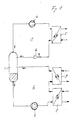
- a compression circuit 1 and a low-pressure circuit 2 for a conventional refrigerant are connected to one another by a liquid separator 3.
- the liquid phase of the refrigerant collects in the lower area, while the upper area is filled with the gas phase of the refrigerant.
- the boundary between the liquid phase and the gas phase is selected such that the two connections of the compression circuit 1 open into the gas collection area, while the line through which the refrigerant is fed to the low-pressure circuit 2 always leads to the liquid collection area, and the line via which the refrigerant is returned from the low-pressure circuit 2 into the liquid separator 3, with the gas collection area of which are connected.
- the compression circuit 1 is designed in a known manner and points in the direction of flow of the refrigerant arranged one behind the other a compressor 4, a condenser 5 and a pressure reducing member in the form of an HP float valve 6.
- the compressor 4 is supplied with gaseous refrigerant from the liquid separator 3, which is compressed by the latter.
- the condenser 5 the compressed refrigerant is condensed by a supplied coolant through heat exchange and then the pressure of the liquid refrigerant in the float valve 6 is reduced to the pressure prevailing in the liquid separator 3.
- the liquid refrigerant flows from the float valve 6 into the liquid separator 3 and collects in the lower area.
- the low-pressure circuit 2 which is fed from the liquid collection area of the liquid separator 3, there are a refrigerant pump 7, an evaporator 8 and a condenser 9 arranged one behind the other in the direction of flow of the refrigerant
- Liquid refrigerant is evaporated to the extent necessary to adequately cool the medium to be cooled, which is also supplied to the evaporator 8.
- the fully or partially evaporated refrigerant passes from the evaporator 8 into the condenser 9, where it is partially or completely liquefied again.
- a medium which is available in sufficient quantity and inexpensively is preferably used as the coolant for condensation of the refrigerant in the condenser 9.
- Preferred media are the outside air or ice or water of an ice store.
- the refrigerant discharged from the condenser 9 to the liquid separator 3 is thus at least partially liquefied.
- the remaining gas phase collects in the upper area of the liquid separator 3 and is taken up by the compression circuit 1 and liquefied in it.
- the condenser 9 has the effect that the amount of gaseous refrigerant still to be liquefied in the compression circuit 1 is relatively small.
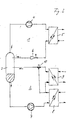
- the refrigeration system according to FIG. 1 is modified so that a three-way valve 10 is inserted into the refrigerant line between the condenser 9 and the liquid separator 3, which valve is additionally connected to the refrigerant outlet of the evaporator 8.
- the three-way valve 10 can be set so that it only connects the output of the condenser 9 in its first switching state and only the output of the evaporator 8 to the liquid separator 3 in its second switching state. In the first switching state, the system thus corresponds to that in FIG. 1, ie evaporator 8 and condenser 9 are connected in series in the refrigerant circuit.
- the condenser 9 In the second switching state, the condenser 9 is bridged by the line leading from the outlet of the evaporator 8 to the three-way valve 10. Since the connection between the output of the capacitor 9 and the Liquid separator 3 is interrupted by the three-way valve 10, the condenser 9 is thus completely removed from the low-pressure refrigerant circuit.
- This second switching state will be selected when the temperature of the coolant supplied to the condenser 9 is higher than that of the refrigerant leaving the evaporator 8. In this case, with the condenser 9 switched on, it would also act as an evaporator and cool the coolant, as a result of which the work to be performed by the compressor 4 would not only not be reduced, but would even be increased.
- the temperature of the coolant for the condenser 9 fluctuates greatly, for example when the outside air is used as the coolant. If the temperature of the outside air exceeds a certain value dependent on the temperature of the refrigerant, for example 25 ° C or 30 ° C, then the three-way valve 10 is switched to the second switching state, so that the condenser 9 is removed from the low-pressure circuit 2 and the Compressor 4 not loaded. If the temperature of the outside air falls below the mentioned value again, the condenser 9 is switched on again and relieves the load on the compressor 4.
- FIG. 3 there is a three-way valve 11 in the refrigerant line between the outlet of the evaporator 8 and the inlet of the condenser 9, which valve is additionally connected directly to the outlet of the refrigerant pump 7.
- the three-way valve 11 can be switched so that it has the output of the evaporator 8 connects to the input of the condenser 9 and interrupts the line between the pump 7 and the condenser 9 (first switching state), ie the system works like that shown in FIG. 1 or so that the line between the evaporator 8 and the condenser 9 interrupted and which is released between the pump 7 and the condenser 9 (second switching state).
- the evaporator 8 In the second switching state, the evaporator 8 is thus removed from the low-pressure circuit 2, as a result of which the condenser 9 takes up the power of the compressor 4 and acts as an evaporator, so that the coolant fed to the condenser 9, cooled and circulated, is cooled and in a reservoir, for example a Ice storage.
- the evaporator 8 In the first switching state of the three-way valve 11, the evaporator 8 is switched on again to cool a medium and the condenser 9 acts to condense the refrigerant, the coolant stored in the reservoir being heated again. 3 is particularly useful if the cooling effect of the evaporator 8 is only needed temporarily.
- the coolant for the condenser 9 is advantageously cooled via the second switching state of the three-way valve 11 when the costs for the energy supplied to the compressor 4 are staggered according to time tariffs and there is a low tariff.
- the first switching state of the three-way valve 11 is then set, as a result of which the evaporator 8 is effective and the refrigerant in the condenser 9 is condensed by heat exchange with the coolant, ie discharge of the cold reservoir.
- the compressor 4 then runs at a much lower output than is actually required for cooling the medium in the evaporator 8, or can even be switched off completely, so that electrical energy is only required for the pump 7. In the subsequent low tariff period, the cold reservoir is recharged via the condenser 9.
- the system according to FIG. 3 can also be used to bring about constant utilization of the compressor 4, so that the power that is only temporarily required by the evaporator 8 can be a multiple of the power constantly supplied by the compressor 4.
- the compressor can therefore be made particularly small.
Landscapes
- Engineering & Computer Science (AREA)
- Physics & Mathematics (AREA)
- Mechanical Engineering (AREA)
- Thermal Sciences (AREA)
- General Engineering & Computer Science (AREA)
- Chemical & Material Sciences (AREA)
- Combustion & Propulsion (AREA)
- Compression-Type Refrigeration Machines With Reversible Cycles (AREA)
- Organic Low-Molecular-Weight Compounds And Preparation Thereof (AREA)
Priority Applications (3)
| Application Number | Priority Date | Filing Date | Title |
|---|---|---|---|
| DE8686730138T DE3669916D1 (de) | 1986-09-16 | 1986-09-16 | Kaelteanlage. |
| AT86730138T ATE51440T1 (de) | 1986-09-16 | 1986-09-16 | Kaelteanlage. |
| EP86730138A EP0260367B1 (fr) | 1986-09-16 | 1986-09-16 | Installation frigorifique |
Applications Claiming Priority (1)
| Application Number | Priority Date | Filing Date | Title |
|---|---|---|---|
| EP86730138A EP0260367B1 (fr) | 1986-09-16 | 1986-09-16 | Installation frigorifique |
Publications (2)
| Publication Number | Publication Date |
|---|---|
| EP0260367A1 true EP0260367A1 (fr) | 1988-03-23 |
| EP0260367B1 EP0260367B1 (fr) | 1990-03-28 |
Family
ID=8196443
Family Applications (1)
| Application Number | Title | Priority Date | Filing Date |
|---|---|---|---|
| EP86730138A Expired - Lifetime EP0260367B1 (fr) | 1986-09-16 | 1986-09-16 | Installation frigorifique |
Country Status (3)
| Country | Link |
|---|---|
| EP (1) | EP0260367B1 (fr) |
| AT (1) | ATE51440T1 (fr) |
| DE (1) | DE3669916D1 (fr) |
Cited By (6)
| Publication number | Priority date | Publication date | Assignee | Title |
|---|---|---|---|---|
| EP0543194A3 (en) * | 1991-11-20 | 1993-08-04 | Air Products And Chemicals, Inc. | Refrigeration apparatus and method of refrigeration |
| EP0595724A1 (fr) * | 1992-10-30 | 1994-05-04 | Jf Cesbron S.A. | Installation de production et de distribution de froid |
| EP1798498A3 (fr) * | 2005-12-13 | 2008-07-09 | Sanden Corporation | Système de refrigération par compression de vapeur |
| EP1855068A3 (fr) * | 2006-05-10 | 2008-11-05 | Sanden Corporation | Cycle de réfrigération à compression de vapeur |
| EP3159626A1 (fr) * | 2015-10-20 | 2017-04-26 | Ulrich Brunner GmbH | Circuit de pompe a chaleur |
| CN109114842A (zh) * | 2018-09-27 | 2019-01-01 | 克莱门特捷联制冷设备(上海)有限公司 | 一种耦合型机房空调系统及其控制方法 |
Citations (3)
| Publication number | Priority date | Publication date | Assignee | Title |
|---|---|---|---|---|
| US2096065A (en) * | 1932-03-23 | 1937-10-19 | Ruppricht Siegfried | Refrigerating system |
| FR2341109A1 (fr) * | 1976-02-13 | 1977-09-09 | Doomernik Cornelis | Accumulateur de froid |
| FR2544470A1 (fr) * | 1982-12-10 | 1984-10-19 | Hiross Int Co | Unite de refroidissement pour fluides dans une installation de conditionnement d'air |
-
1986
- 1986-09-16 DE DE8686730138T patent/DE3669916D1/de not_active Expired - Fee Related
- 1986-09-16 AT AT86730138T patent/ATE51440T1/de not_active IP Right Cessation
- 1986-09-16 EP EP86730138A patent/EP0260367B1/fr not_active Expired - Lifetime
Patent Citations (3)
| Publication number | Priority date | Publication date | Assignee | Title |
|---|---|---|---|---|
| US2096065A (en) * | 1932-03-23 | 1937-10-19 | Ruppricht Siegfried | Refrigerating system |
| FR2341109A1 (fr) * | 1976-02-13 | 1977-09-09 | Doomernik Cornelis | Accumulateur de froid |
| FR2544470A1 (fr) * | 1982-12-10 | 1984-10-19 | Hiross Int Co | Unite de refroidissement pour fluides dans une installation de conditionnement d'air |
Cited By (7)
| Publication number | Priority date | Publication date | Assignee | Title |
|---|---|---|---|---|
| EP0543194A3 (en) * | 1991-11-20 | 1993-08-04 | Air Products And Chemicals, Inc. | Refrigeration apparatus and method of refrigeration |
| EP0595724A1 (fr) * | 1992-10-30 | 1994-05-04 | Jf Cesbron S.A. | Installation de production et de distribution de froid |
| FR2697619A1 (fr) * | 1992-10-30 | 1994-05-06 | Cesbron Jf | Installation de production et de distribution de froid d'un nouveau type. |
| EP1798498A3 (fr) * | 2005-12-13 | 2008-07-09 | Sanden Corporation | Système de refrigération par compression de vapeur |
| EP1855068A3 (fr) * | 2006-05-10 | 2008-11-05 | Sanden Corporation | Cycle de réfrigération à compression de vapeur |
| EP3159626A1 (fr) * | 2015-10-20 | 2017-04-26 | Ulrich Brunner GmbH | Circuit de pompe a chaleur |
| CN109114842A (zh) * | 2018-09-27 | 2019-01-01 | 克莱门特捷联制冷设备(上海)有限公司 | 一种耦合型机房空调系统及其控制方法 |
Also Published As
| Publication number | Publication date |
|---|---|
| DE3669916D1 (de) | 1990-05-03 |
| ATE51440T1 (de) | 1990-04-15 |
| EP0260367B1 (fr) | 1990-03-28 |
Similar Documents
| Publication | Publication Date | Title |
|---|---|---|
| DE3220335C2 (de) | Wärmepumpensystem mit einer Kältemittelmischung | |
| EP0333632B1 (fr) | Installation pour la compression d'hydrogene gazeuz | |
| DE3805987C2 (fr) | ||
| DE4019669C2 (de) | Adsorptionsthermischer Speicher | |
| DE3875006T2 (de) | Waermepumpensystem. | |
| DE69004009T2 (de) | Kühlanlage mit Zusatzwärmespeicher. | |
| DE69513765T2 (de) | Kälteanlage | |
| DE60218793T2 (de) | Kältemittelkreislauf | |
| DE68926966T2 (de) | Wärmepumpengerät | |
| EP2447096A1 (fr) | Dispositif de pompe à chaleur doté d'une fonction de dégivrage | |
| EP0260367A1 (fr) | Installation frigorifique | |
| DE102008043807A1 (de) | Kälteanlage | |
| EP0593495B1 (fr) | Dispositif frigorifique | |
| EP2215412A1 (fr) | Installation pour le refroidissement, le chauffage ou la climatisation, en particulier installations frigorifiques | |
| DE2758547A1 (de) | Verfahren zur verbesserung der energiebilanz von absorptionskaelteanlagen | |
| DE112017005948T5 (de) | Klimatisierungsvorrichtung | |
| DE102014000571A1 (de) | Brennstoffzellensystem | |
| EP0239837A2 (fr) | Procédé pour la récupération de la chaleur de condensation d'un système frigorifique et système frigorifique pour la mise en oeuvre du procédé | |
| EP0152608B1 (fr) | Procédé de commande d'une installation frigorifique complexe | |
| EP2473795A2 (fr) | Pompe à chaleur | |
| DE8625036U1 (de) | Kühlvorrichtung | |
| DE8712812U1 (de) | Drucklufttrockner | |
| DE10318655B3 (de) | Klimatisierungssystem für ein Kraftfahrzeug und Verfahren zum Betreiben desselben | |
| DE19832682C2 (de) | Abtaueinrichtung für einen Verdampfer einer Wärmepumpe oder eines Klimageräts | |
| DE2719995A1 (de) | Absorptionskaelteanlage |
Legal Events
| Date | Code | Title | Description |
|---|---|---|---|
| PUAI | Public reference made under article 153(3) epc to a published international application that has entered the european phase |
Free format text: ORIGINAL CODE: 0009012 |
|
| AK | Designated contracting states |
Kind code of ref document: A1 Designated state(s): AT BE CH DE FR GB IT LI LU NL SE |
|
| 17P | Request for examination filed |
Effective date: 19880303 |
|
| 17Q | First examination report despatched |
Effective date: 19881020 |
|
| GRAA | (expected) grant |
Free format text: ORIGINAL CODE: 0009210 |
|
| AK | Designated contracting states |
Kind code of ref document: B1 Designated state(s): AT BE CH DE FR GB IT LI LU NL SE |
|
| REF | Corresponds to: |
Ref document number: 51440 Country of ref document: AT Date of ref document: 19900415 Kind code of ref document: T |
|
| REF | Corresponds to: |
Ref document number: 3669916 Country of ref document: DE Date of ref document: 19900503 |
|
| GBT | Gb: translation of ep patent filed (gb section 77(6)(a)/1977) | ||
| ET | Fr: translation filed | ||
| ITF | It: translation for a ep patent filed | ||
| RAP2 | Party data changed (patent owner data changed or rights of a patent transferred) |
Owner name: SMENTEK, ANNEMARIE |
|
| NLT2 | Nl: modifications (of names), taken from the european patent patent bulletin |
Owner name: ANNEMARIE SMENTEK TE BERLIJN, BONDSREPUBLIEK DUITS |
|
| PLBE | No opposition filed within time limit |
Free format text: ORIGINAL CODE: 0009261 |
|
| STAA | Information on the status of an ep patent application or granted ep patent |
Free format text: STATUS: NO OPPOSITION FILED WITHIN TIME LIMIT |
|
| 26N | No opposition filed | ||
| PGFP | Annual fee paid to national office [announced via postgrant information from national office to epo] |
Ref country code: GB Payment date: 19930901 Year of fee payment: 8 |
|
| PGFP | Annual fee paid to national office [announced via postgrant information from national office to epo] |
Ref country code: BE Payment date: 19930914 Year of fee payment: 8 |
|
| PGFP | Annual fee paid to national office [announced via postgrant information from national office to epo] |
Ref country code: LU Payment date: 19930915 Year of fee payment: 8 |
|
| PGFP | Annual fee paid to national office [announced via postgrant information from national office to epo] |
Ref country code: SE Payment date: 19930916 Year of fee payment: 8 Ref country code: FR Payment date: 19930916 Year of fee payment: 8 |
|
| PGFP | Annual fee paid to national office [announced via postgrant information from national office to epo] |
Ref country code: AT Payment date: 19930924 Year of fee payment: 8 |
|
| ITTA | It: last paid annual fee | ||
| PGFP | Annual fee paid to national office [announced via postgrant information from national office to epo] |
Ref country code: NL Payment date: 19930930 Year of fee payment: 8 Ref country code: CH Payment date: 19930930 Year of fee payment: 8 |
|
| PGFP | Annual fee paid to national office [announced via postgrant information from national office to epo] |
Ref country code: DE Payment date: 19931011 Year of fee payment: 8 |
|
| EPTA | Lu: last paid annual fee | ||
| PG25 | Lapsed in a contracting state [announced via postgrant information from national office to epo] |
Ref country code: LU Free format text: LAPSE BECAUSE OF NON-PAYMENT OF DUE FEES Effective date: 19940916 Ref country code: GB Effective date: 19940916 Ref country code: AT Effective date: 19940916 |
|
| PG25 | Lapsed in a contracting state [announced via postgrant information from national office to epo] |
Ref country code: SE Effective date: 19940917 |
|
| PG25 | Lapsed in a contracting state [announced via postgrant information from national office to epo] |
Ref country code: LI Effective date: 19940930 Ref country code: CH Effective date: 19940930 Ref country code: BE Effective date: 19940930 |
|
| EAL | Se: european patent in force in sweden |
Ref document number: 86730138.4 |
|
| BERE | Be: lapsed |
Owner name: SMENTEK ANNEMARIE Effective date: 19940930 |
|
| PG25 | Lapsed in a contracting state [announced via postgrant information from national office to epo] |
Ref country code: NL Effective date: 19950401 |
|
| GBPC | Gb: european patent ceased through non-payment of renewal fee |
Effective date: 19940916 |
|
| NLV4 | Nl: lapsed or anulled due to non-payment of the annual fee | ||
| PG25 | Lapsed in a contracting state [announced via postgrant information from national office to epo] |
Ref country code: FR Effective date: 19950531 |
|
| REG | Reference to a national code |
Ref country code: CH Ref legal event code: PL |
|
| PG25 | Lapsed in a contracting state [announced via postgrant information from national office to epo] |
Ref country code: DE Effective date: 19950601 |
|
| EUG | Se: european patent has lapsed |
Ref document number: 86730138.4 |
|
| REG | Reference to a national code |
Ref country code: FR Ref legal event code: ST |
|
| PG25 | Lapsed in a contracting state [announced via postgrant information from national office to epo] |
Ref country code: IT Free format text: LAPSE BECAUSE OF NON-PAYMENT OF DUE FEES;WARNING: LAPSES OF ITALIAN PATENTS WITH EFFECTIVE DATE BEFORE 2007 MAY HAVE OCCURRED AT ANY TIME BEFORE 2007. THE CORRECT EFFECTIVE DATE MAY BE DIFFERENT FROM THE ONE RECORDED. Effective date: 20050916 |