EP0260372A1 - Dispositif de limitation de la vitesse d'un véhicule automobile - Google Patents
Dispositif de limitation de la vitesse d'un véhicule automobile Download PDFInfo
- Publication number
- EP0260372A1 EP0260372A1 EP87103449A EP87103449A EP0260372A1 EP 0260372 A1 EP0260372 A1 EP 0260372A1 EP 87103449 A EP87103449 A EP 87103449A EP 87103449 A EP87103449 A EP 87103449A EP 0260372 A1 EP0260372 A1 EP 0260372A1
- Authority
- EP
- European Patent Office
- Prior art keywords
- speed
- signal
- speed signal
- vehicle
- control circuit
- Prior art date
- Legal status (The legal status is an assumption and is not a legal conclusion. Google has not performed a legal analysis and makes no representation as to the accuracy of the status listed.)
- Granted
Links
Images

Classifications
-
- B—PERFORMING OPERATIONS; TRANSPORTING
- B60—VEHICLES IN GENERAL
- B60K—ARRANGEMENT OR MOUNTING OF PROPULSION UNITS OR OF TRANSMISSIONS IN VEHICLES; ARRANGEMENT OR MOUNTING OF PLURAL DIVERSE PRIME-MOVERS IN VEHICLES; AUXILIARY DRIVES FOR VEHICLES; INSTRUMENTATION OR DASHBOARDS FOR VEHICLES; ARRANGEMENTS IN CONNECTION WITH COOLING, AIR INTAKE, GAS EXHAUST OR FUEL SUPPLY OF PROPULSION UNITS IN VEHICLES
- B60K31/00—Vehicle fittings, acting on a single sub-unit only, for automatically controlling vehicle speed, i.e. preventing speed from exceeding an arbitrarily established velocity or maintaining speed at a particular velocity, as selected by the vehicle operator
- B60K31/02—Vehicle fittings, acting on a single sub-unit only, for automatically controlling vehicle speed, i.e. preventing speed from exceeding an arbitrarily established velocity or maintaining speed at a particular velocity, as selected by the vehicle operator including electrically actuated servomechanism
- B60K31/04—Vehicle fittings, acting on a single sub-unit only, for automatically controlling vehicle speed, i.e. preventing speed from exceeding an arbitrarily established velocity or maintaining speed at a particular velocity, as selected by the vehicle operator including electrically actuated servomechanism and means for comparing one electrical quantity, e.g. voltage, pulse, waveform, flux, or the like, with another quantity of a like kind, which comparison means is involved in the development of an electrical signal which is fed into the controlling means
-
- B—PERFORMING OPERATIONS; TRANSPORTING
- B60—VEHICLES IN GENERAL
- B60W—CONJOINT CONTROL OF VEHICLE SUB-UNITS OF DIFFERENT TYPE OR DIFFERENT FUNCTION; CONTROL SYSTEMS SPECIALLY ADAPTED FOR HYBRID VEHICLES; ROAD VEHICLE DRIVE CONTROL SYSTEMS FOR PURPOSES NOT RELATED TO THE CONTROL OF A PARTICULAR SUB-UNIT
- B60W30/00—Purposes of road vehicle drive control systems not related to the control of a particular sub-unit, e.g. of systems using conjoint control of vehicle sub-units
- B60W30/14—Adaptive cruise control
- B60W30/143—Speed control
- B60W30/146—Speed limiting
Definitions
- the invention relates to a device for limiting the speed of a motor vehicle, a signal corresponding to the speed (speed signal) being fed to a control circuit for driving the motor vehicle.
- speed limiters are used in motor vehicles, especially in commercial vehicles, which prevent a predetermined maximum speed from being exceeded, although an exceeding would be possible due to the engine power and the axle ratio.
- speed limiters require a signal to perform their function, which represents the actual value of the vehicle speed (hereinafter referred to as the speed signal). This falls Signal from manipulation or a technical defect, the speed limiter is ineffective, so that it is possible to exceed the permissible maximum speed.
- the object of the invention is to provide a device for limiting the speed of a motor vehicle with increased operational safety.
- the device according to the invention is characterized in that a signal (speed signal) corresponding to the engine speed is also fed to the control circuit and that the speed signal is effective to limit the speed of the vehicle if the speed signal fails.
- the device according to the invention also limits the vehicle speed when the speed signal is disturbed or has failed.
- the limitation according to the speed signals is designed in such a way that the permissible maximum speed is not exceeded even at the longest gear ratio. At other gear ratios, the limitation starts at the same speed, but at low speed. However, this is not a disadvantage because the driver has full engine power until the maximum speed value is reached. This ensures that there is sufficient power for operation with a failed speed signal. This "emergency driving mode" ensures sufficient movement of the vehicle.
- control circuit comprises a microcomputer, to which the speed signal, the speed signal and a setpoint for the position of a motor actuator is fed.
- the microcomputer can be programmed within the scope of the expert in such a way that it performs the functions required for switching from the speed signal to the speed signal.
- the speed signal is a pulse signal, the pulse width in the entire speed range being less than 100%, that the pulse signal is fed to the control circuit via a circuit which supplies the control circuit with a voltage when the speed signal is interrupted, which corresponds to a pulse width of 100%.
- a simple embodiment of this development consists in the circuit being a transistor switching stage with a pull-up resistor.
- This circuit which can be arranged in the input area of the control circuit, requires only a few components and supplies the control circuit with a corresponding voltage if the speed signal fails.
- the speed signal is also effective to limit the speed of the vehicle when the speed signal is below a value that corresponds to a predetermined low speed of the vehicle.
- a switch is made to a speed limitation by the speed signal.
- this also limits the engine speed when starting.
- a further development of the invention in which a short-circuiting of the speed sensor line or the corresponding input of the control device is taken into account without limiting the speed when opening, is characterized in that the speed signal is also effective for limiting the vehicle speed when the speed signal exceeds is a predetermined value, the clutch is closed and a gear is engaged and no speed signal occurs.
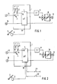
- the control unit 1 of an e-gas system is supplied with the output signal of an encoder 3 connected to an accelerator pedal 2 via an input 18 as the desired variable.
- the control device 1 comprises a microcomputer 4 and peripheral circuits, of which only the circuit consisting of a transistor 5, a load resistor 6 and a pull-up resistor 7 is shown.
- the microcomputer sends signals corresponding to the position of the accelerator pedal 2 to the drive 9 of a throttle valve 10 via a power stage 8.
- another engine actuator can also be used within the scope of the invention, for example the controller of a diesel injection pump.
- the throttle valve 10 is connected to an encoder 11 which supplies the control unit with a signal corresponding to the throttle valve position.
- the microcomputer 4 is thus part of a control circuit with which the throttle valve 10 is brought into a position specified by the accelerator pedal 2.
- the speed signal consists of pulse width modulated pulses, the pulse width not taking 100% within the speed range in question. If the line between the transmitter 13 and the control unit is interrupted or the transmitter 13 has failed, the transistor 5 remains in the conductive state, so that the transistor 5 continuously supplies low voltage from the ground pole to the input 15 of the microcomputer. This evaluates this as a failure of the speed signal and carries out the further limitation of the speed with the aid of the speed signal generated by a further encoder 16, which is also fed to the microcomputer 4.
- a further development can be provided which also enables the vehicle speed to be limited if the input for the speed signal is short-circuited by manipulation.
- the speed signal is used for control when the speed signal is below a predetermined value. This is the case both when starting up and when the input is closed. If there is no short circuit, however, after the vehicle has started off, the speed signal becomes greater than the predetermined value, so that it is used to limit the vehicle speed.
- the speed limit is also removed when the input is short-circuited.
- the limitation by the speed signal does not take effect, however, if the clutch is not closed or no gear is engaged. This does not limit the speed when starting.
- the device according to FIG. 2 is supplemented by two switches 21, 22, which are connected to the clutch and the transmission.
Landscapes
- Engineering & Computer Science (AREA)
- Transportation (AREA)
- Mechanical Engineering (AREA)
- Automation & Control Theory (AREA)
- Chemical & Material Sciences (AREA)
- Combustion & Propulsion (AREA)
- Controls For Constant Speed Travelling (AREA)
- Control Of Velocity Or Acceleration (AREA)
- Electrical Control Of Air Or Fuel Supplied To Internal-Combustion Engine (AREA)
- Control Of Vehicle Engines Or Engines For Specific Uses (AREA)
Applications Claiming Priority (2)
| Application Number | Priority Date | Filing Date | Title |
|---|---|---|---|
| DE3631289 | 1986-09-13 | ||
| DE19863631289 DE3631289A1 (de) | 1986-09-13 | 1986-09-13 | Einrichtung zur begrenzung der geschwindigkeit eines kraftfahrzeugs |
Publications (2)
| Publication Number | Publication Date |
|---|---|
| EP0260372A1 true EP0260372A1 (fr) | 1988-03-23 |
| EP0260372B1 EP0260372B1 (fr) | 1990-08-01 |
Family
ID=6309583
Family Applications (1)
| Application Number | Title | Priority Date | Filing Date |
|---|---|---|---|
| EP87103449A Expired - Lifetime EP0260372B1 (fr) | 1986-09-13 | 1987-03-10 | Dispositif de limitation de la vitesse d'un véhicule automobile |
Country Status (4)
| Country | Link |
|---|---|
| EP (1) | EP0260372B1 (fr) |
| JP (1) | JPS6371435A (fr) |
| BR (1) | BR8704722A (fr) |
| DE (2) | DE3631289A1 (fr) |
Cited By (5)
| Publication number | Priority date | Publication date | Assignee | Title |
|---|---|---|---|---|
| GB2200002B (en) * | 1986-12-23 | 1991-09-11 | Qualter Hall & Co Limited | Microprocessor-based controllers especially for hazardous environment |
| ES2042399A2 (es) * | 1992-03-05 | 1993-12-01 | Guasch Gonzalez Antoni | Sistema para la limitacion de velocidad de vehiculos. |
| GB2280285A (en) * | 1993-07-23 | 1995-01-25 | Caterpillar Inc | Engine speed control |
| US5385128A (en) * | 1992-11-28 | 1995-01-31 | Robert Bosch Gmbh | Method and device for limiting vehicle speed |
| WO2000005092A1 (fr) * | 1998-07-20 | 2000-02-03 | Marco Magliocchetti | Limiteur de vitesse programmable pour automobiles et motocycles |
Families Citing this family (1)
| Publication number | Priority date | Publication date | Assignee | Title |
|---|---|---|---|---|
| JP2556924B2 (ja) * | 1990-05-15 | 1996-11-27 | 三菱電機株式会社 | 内燃機関制御方法 |
Citations (5)
| Publication number | Priority date | Publication date | Assignee | Title |
|---|---|---|---|---|
| US3804193A (en) * | 1971-09-30 | 1974-04-16 | Nippon Denso Co | Automatic constant speed control system for vehicles |
| FR2254252A5 (en) * | 1973-12-07 | 1975-07-04 | Auray Didier | Speed control system for vehicle - uses acceleration and variation of acceleration signals |
| DE3108378A1 (de) * | 1980-03-14 | 1982-02-04 | The Singer Co., 06904 Stamford, Conn. | Verfahren sowie schaltung zur steuerung der drehzahl von motoren, insbesondere von kreiselmotoren |
| DE3142360A1 (de) * | 1981-10-26 | 1983-05-05 | Bosch und Pierburg System oHG, 4040 Neuss | Verfahren und vorrichtung zur regelung der drehzahl einer brennkraftmaschine |
| DE3441070A1 (de) | 1983-11-09 | 1985-06-05 | Diesel Kiki Co. Ltd., Tokio/Tokyo | Einrichtung zum steuern der geschwindigkeit eines fahrzeugs mit verbrennungsmotor |
Family Cites Families (4)
| Publication number | Priority date | Publication date | Assignee | Title |
|---|---|---|---|---|
| DE3026423A1 (de) * | 1980-07-11 | 1982-02-04 | Ulo-Werk Moritz Ullmann Gmbh & Co Kg, 7340 Geislingen | Geschwindigkeitsbegrenzungsvorrichtung fuer kraftfahrzeuge |
| JPS5912145A (ja) * | 1982-07-12 | 1984-01-21 | Nissan Motor Co Ltd | エンジンの燃料供給制御装置 |
| FR2537742B1 (fr) * | 1982-12-09 | 1985-07-26 | Jaeger | Dispositif de detection de pannes sur des limiteurs de vitesse avec intervention automatique sur le fonctionnement du limiteur |
| JPS60162023A (ja) * | 1984-01-31 | 1985-08-23 | Isuzu Motors Ltd | エンジン自動停止・再始動制御装置 |
-
1986
- 1986-09-13 DE DE19863631289 patent/DE3631289A1/de not_active Ceased
-
1987
- 1987-03-10 EP EP87103449A patent/EP0260372B1/fr not_active Expired - Lifetime
- 1987-03-10 DE DE8787103449T patent/DE3764048D1/de not_active Expired - Lifetime
- 1987-05-29 JP JP62131974A patent/JPS6371435A/ja active Pending
- 1987-09-11 BR BR8704722A patent/BR8704722A/pt not_active IP Right Cessation
Patent Citations (5)
| Publication number | Priority date | Publication date | Assignee | Title |
|---|---|---|---|---|
| US3804193A (en) * | 1971-09-30 | 1974-04-16 | Nippon Denso Co | Automatic constant speed control system for vehicles |
| FR2254252A5 (en) * | 1973-12-07 | 1975-07-04 | Auray Didier | Speed control system for vehicle - uses acceleration and variation of acceleration signals |
| DE3108378A1 (de) * | 1980-03-14 | 1982-02-04 | The Singer Co., 06904 Stamford, Conn. | Verfahren sowie schaltung zur steuerung der drehzahl von motoren, insbesondere von kreiselmotoren |
| DE3142360A1 (de) * | 1981-10-26 | 1983-05-05 | Bosch und Pierburg System oHG, 4040 Neuss | Verfahren und vorrichtung zur regelung der drehzahl einer brennkraftmaschine |
| DE3441070A1 (de) | 1983-11-09 | 1985-06-05 | Diesel Kiki Co. Ltd., Tokio/Tokyo | Einrichtung zum steuern der geschwindigkeit eines fahrzeugs mit verbrennungsmotor |
Non-Patent Citations (3)
| Title |
|---|
| ATZ AUTOMOBILTECHNISCHE ZEITSCHRIFT, vol. 85, 1983, pages 9 |
| Elektronik, Nr. 10, 17. Mai 1985, Munchen W. SCHUMACHER, P. ROJEK, H.-H. LETAS "Hochauflosende Lage- und Drehzahlerfassung Optischer Geber fur Schnelle Stellantriebe" seiten 65-68 * seite 66 * * |
| GERHARD KOLBERG: "Elektronische Motorsteuerung für Kraftfahrzeuge", MTZ MOTORTECHNISCHE ZEITSCHRIFT, vol. 46, 1985, pages 129 - 133 |
Cited By (7)
| Publication number | Priority date | Publication date | Assignee | Title |
|---|---|---|---|---|
| GB2200002B (en) * | 1986-12-23 | 1991-09-11 | Qualter Hall & Co Limited | Microprocessor-based controllers especially for hazardous environment |
| ES2042399A2 (es) * | 1992-03-05 | 1993-12-01 | Guasch Gonzalez Antoni | Sistema para la limitacion de velocidad de vehiculos. |
| US5385128A (en) * | 1992-11-28 | 1995-01-31 | Robert Bosch Gmbh | Method and device for limiting vehicle speed |
| GB2280285A (en) * | 1993-07-23 | 1995-01-25 | Caterpillar Inc | Engine speed control |
| GB2280285B (en) * | 1993-07-23 | 1997-08-20 | Caterpillar Inc | Redundant speed sensor for engine control |
| ES2112722A2 (es) * | 1993-07-23 | 1998-04-01 | Caterpillar Inc | Director de velocidad redundante para control del motor. |
| WO2000005092A1 (fr) * | 1998-07-20 | 2000-02-03 | Marco Magliocchetti | Limiteur de vitesse programmable pour automobiles et motocycles |
Also Published As
| Publication number | Publication date |
|---|---|
| DE3764048D1 (de) | 1990-09-06 |
| EP0260372B1 (fr) | 1990-08-01 |
| BR8704722A (pt) | 1988-05-03 |
| DE3631289A1 (de) | 1988-03-24 |
| JPS6371435A (ja) | 1988-03-31 |
Similar Documents
| Publication | Publication Date | Title |
|---|---|---|
| EP0464041B1 (fr) | Procede pour determiner au moins une position terminale d'un dispositif d'ajustement dans un vehicule automobile | |
| EP0581124A2 (fr) | Système de commande pour transmission avec mode d'opération de secours | |
| DE69013559T2 (de) | Von einem Motor angetriebene Servolenkung. | |
| DE2703495A1 (de) | Drehmomentwerkzeugsystem | |
| DE3612905A1 (de) | Verfahren zum ausloesen einer schaltfunktion | |
| DE3421387C2 (fr) | ||
| EP1134145A2 (fr) | Dispositif de protection pour un système de direction électrique | |
| EP0260372A1 (fr) | Dispositif de limitation de la vitesse d'un véhicule automobile | |
| DE10107962A1 (de) | Verfahren und Vorrichtung zur Steuerung einer Kupplung | |
| EP0279908B1 (fr) | Méthode et dispositif de montage pour amortir des oscillations d'un véhicule | |
| DE102016221498B4 (de) | Verfahren und Vorrichtung zur Steuerung einer Dämpferkupplung zur Verhinderung von Motorabwürgung | |
| EP0371151B1 (fr) | Circuit de sécurité pour système électronique de commande ou de régulation de la vitesse de véhicules à moteur | |
| DE3743308A1 (de) | Verfahren und vorrichtung zur ueberwachung eines antriebsmotorsollwertgeber | |
| EP1036936A1 (fr) | Système de surveillance pour dispositif de démarrage | |
| DE3334723A1 (de) | Einrichtung zur steuerung eines motors und/oder einer automatisierten kupplung von kraftfahrzeugen | |
| DE3146934C2 (de) | Anordnung zum Steuern einer elektromagnetischen Kupplung für ein Kraftfahrzeug | |
| DE2754439C2 (de) | Einrichtung zum Regeln der Fahrgeschwindigkeit eines Kraftfahrzeugs | |
| DE2755370A1 (de) | Einrichtung zum regeln der fahrgeschwindigkeit eines kraftfahrzeugs | |
| DE3921011C2 (fr) | ||
| EP0250873B1 (fr) | Dispositif pour ajuster la vitesse de déplacement d'un véhicule automobile | |
| DE2844829A1 (de) | Einrichtung zum regeln der fahrgeschwindigkeit eines kraftfahrzeugs | |
| EP0140152A2 (fr) | Dispositif de commande d'un moteur à combustion interne en décélération | |
| DE3344665C2 (de) | Geschwindigkeits-Begrenzungseinrichtung für ein Kraftfahrzeug | |
| DE4037550C2 (de) | Bedienungseinrichtung für eine eine Steuereinheit aufweisende Fahrgeschwindigkeitsregelanlage eines Kraftfahrzeuges | |
| DE68925770T2 (de) | Servomotorlenkeinrichtung |
Legal Events
| Date | Code | Title | Description |
|---|---|---|---|
| PUAI | Public reference made under article 153(3) epc to a published international application that has entered the european phase |
Free format text: ORIGINAL CODE: 0009012 |
|
| 17P | Request for examination filed |
Effective date: 19880119 |
|
| AK | Designated contracting states |
Kind code of ref document: A1 Designated state(s): DE FR GB NL SE |
|
| 17Q | First examination report despatched |
Effective date: 19881209 |
|
| GRAA | (expected) grant |
Free format text: ORIGINAL CODE: 0009210 |
|
| AK | Designated contracting states |
Kind code of ref document: B1 Designated state(s): DE FR GB NL SE |
|
| GBT | Gb: translation of ep patent filed (gb section 77(6)(a)/1977) | ||
| ET | Fr: translation filed | ||
| REF | Corresponds to: |
Ref document number: 3764048 Country of ref document: DE Date of ref document: 19900906 |
|
| PGFP | Annual fee paid to national office [announced via postgrant information from national office to epo] |
Ref country code: NL Payment date: 19910331 Year of fee payment: 5 |
|
| PLBI | Opposition filed |
Free format text: ORIGINAL CODE: 0009260 |
|
| 26 | Opposition filed |
Opponent name: ROBERT BOSCH GMBH Effective date: 19910420 |
|
| NLR1 | Nl: opposition has been filed with the epo |
Opponent name: ROBERT BOSCH GMBH |
|
| PG25 | Lapsed in a contracting state [announced via postgrant information from national office to epo] |
Ref country code: DE Effective date: 19920101 |
|
| PG25 | Lapsed in a contracting state [announced via postgrant information from national office to epo] |
Ref country code: NL Effective date: 19921001 |
|
| NLV4 | Nl: lapsed or anulled due to non-payment of the annual fee | ||
| PGFP | Annual fee paid to national office [announced via postgrant information from national office to epo] |
Ref country code: SE Payment date: 19940223 Year of fee payment: 8 |
|
| EAL | Se: european patent in force in sweden |
Ref document number: 87103449.2 |
|
| PG25 | Lapsed in a contracting state [announced via postgrant information from national office to epo] |
Ref country code: SE Effective date: 19950311 |
|
| EUG | Se: european patent has lapsed |
Ref document number: 87103449.2 |
|
| PGFP | Annual fee paid to national office [announced via postgrant information from national office to epo] |
Ref country code: GB Payment date: 19960215 Year of fee payment: 10 |
|
| PGFP | Annual fee paid to national office [announced via postgrant information from national office to epo] |
Ref country code: FR Payment date: 19960220 Year of fee payment: 10 |
|
| RDAG | Patent revoked |
Free format text: ORIGINAL CODE: 0009271 |
|
| STAA | Information on the status of an ep patent application or granted ep patent |
Free format text: STATUS: PATENT REVOKED |
|
| 27W | Patent revoked |
Effective date: 19960106 |
|
| GBPR | Gb: patent revoked under art. 102 of the ep convention designating the uk as contracting state |
Free format text: 960106 |