EP0260911A2 - Dachsystem - Google Patents
Dachsystem Download PDFInfo
- Publication number
- EP0260911A2 EP0260911A2 EP87308100A EP87308100A EP0260911A2 EP 0260911 A2 EP0260911 A2 EP 0260911A2 EP 87308100 A EP87308100 A EP 87308100A EP 87308100 A EP87308100 A EP 87308100A EP 0260911 A2 EP0260911 A2 EP 0260911A2
- Authority
- EP
- European Patent Office
- Prior art keywords
- trough
- roof structure
- insulation
- mass
- deck
- Prior art date
- Legal status (The legal status is an assumption and is not a legal conclusion. Google has not performed a legal analysis and makes no representation as to the accuracy of the status listed.)
- Withdrawn
Links
- 238000009413 insulation Methods 0.000 claims abstract description 51
- 239000012774 insulation material Substances 0.000 claims abstract description 25
- 239000008187 granular material Substances 0.000 claims abstract description 6
- 239000000463 material Substances 0.000 claims description 48
- 229920001169 thermoplastic Polymers 0.000 claims description 36
- 239000004416 thermosoftening plastic Substances 0.000 claims description 36
- 230000002745 absorbent Effects 0.000 claims description 31
- 239000002250 absorbent Substances 0.000 claims description 31
- 239000006260 foam Substances 0.000 claims description 15
- XLYOFNOQVPJJNP-UHFFFAOYSA-N water Substances O XLYOFNOQVPJJNP-UHFFFAOYSA-N 0.000 claims description 14
- 239000003063 flame retardant Substances 0.000 claims description 10
- 239000012528 membrane Substances 0.000 claims description 9
- 239000004568 cement Substances 0.000 claims description 8
- 239000010440 gypsum Substances 0.000 claims description 7
- 229910052602 gypsum Inorganic materials 0.000 claims description 7
- XEEYBQQBJWHFJM-UHFFFAOYSA-N Iron Chemical compound [Fe] XEEYBQQBJWHFJM-UHFFFAOYSA-N 0.000 claims description 6
- CSNNHWWHGAXBCP-UHFFFAOYSA-L Magnesium sulfate Chemical class [Mg+2].[O-][S+2]([O-])([O-])[O-] CSNNHWWHGAXBCP-UHFFFAOYSA-L 0.000 claims description 6
- 239000004576 sand Substances 0.000 claims description 6
- 239000004927 clay Substances 0.000 claims description 5
- 239000011521 glass Substances 0.000 claims description 4
- 238000000034 method Methods 0.000 claims description 4
- 239000010455 vermiculite Substances 0.000 claims description 4
- 235000019354 vermiculite Nutrition 0.000 claims description 4
- 229910052902 vermiculite Inorganic materials 0.000 claims description 4
- -1 firestop caulking Substances 0.000 claims description 3
- 239000010881 fly ash Substances 0.000 claims description 3
- 239000003365 glass fiber Substances 0.000 claims description 3
- 239000011810 insulating material Substances 0.000 claims description 3
- 229910052742 iron Inorganic materials 0.000 claims description 3
- 235000019341 magnesium sulphate Nutrition 0.000 claims description 3
- 238000004519 manufacturing process Methods 0.000 claims description 3
- 229920006327 polystyrene foam Polymers 0.000 claims description 3
- 239000004800 polyvinyl chloride Substances 0.000 claims description 3
- 239000000843 powder Substances 0.000 claims description 3
- 239000011435 rock Substances 0.000 claims description 3
- 239000002893 slag Substances 0.000 claims description 3
- 229920005830 Polyurethane Foam Polymers 0.000 claims description 2
- 229920001228 polyisocyanate Polymers 0.000 claims description 2
- 239000005056 polyisocyanate Substances 0.000 claims description 2
- 239000011496 polyurethane foam Substances 0.000 claims description 2
- 229920000915 polyvinyl chloride Polymers 0.000 claims description 2
- 230000000284 resting effect Effects 0.000 claims 1
- 229910052751 metal Inorganic materials 0.000 description 40
- 239000002184 metal Substances 0.000 description 40
- 239000012815 thermoplastic material Substances 0.000 description 5
- 229910000831 Steel Inorganic materials 0.000 description 4
- 238000010276 construction Methods 0.000 description 4
- 229920003023 plastic Polymers 0.000 description 4
- 239000004033 plastic Substances 0.000 description 4
- 239000002984 plastic foam Substances 0.000 description 4
- 239000010959 steel Substances 0.000 description 4
- 239000011094 fiberboard Substances 0.000 description 3
- 239000007789 gas Substances 0.000 description 3
- 238000002844 melting Methods 0.000 description 3
- 230000008018 melting Effects 0.000 description 3
- 239000012768 molten material Substances 0.000 description 3
- 230000000979 retarding effect Effects 0.000 description 3
- 239000004709 Chlorinated polyethylene Substances 0.000 description 2
- 229920002943 EPDM rubber Polymers 0.000 description 2
- 229920002367 Polyisobutene Polymers 0.000 description 2
- 229910052782 aluminium Inorganic materials 0.000 description 2
- XAGFODPZIPBFFR-UHFFFAOYSA-N aluminium Chemical compound [Al] XAGFODPZIPBFFR-UHFFFAOYSA-N 0.000 description 2
- 230000008901 benefit Effects 0.000 description 2
- 239000011230 binding agent Substances 0.000 description 2
- 230000001419 dependent effect Effects 0.000 description 2
- 229920002681 hypalon Polymers 0.000 description 2
- 238000005304 joining Methods 0.000 description 2
- 239000000155 melt Substances 0.000 description 2
- 230000001681 protective effect Effects 0.000 description 2
- 239000004575 stone Substances 0.000 description 2
- 229920001187 thermosetting polymer Polymers 0.000 description 2
- 238000003466 welding Methods 0.000 description 2
- NLHHRLWOUZZQLW-UHFFFAOYSA-N Acrylonitrile Chemical compound C=CC#N NLHHRLWOUZZQLW-UHFFFAOYSA-N 0.000 description 1
- 238000010521 absorption reaction Methods 0.000 description 1
- 239000010426 asphalt Substances 0.000 description 1
- 230000000712 assembly Effects 0.000 description 1
- 238000000429 assembly Methods 0.000 description 1
- QVGXLLKOCUKJST-UHFFFAOYSA-N atomic oxygen Chemical compound [O] QVGXLLKOCUKJST-UHFFFAOYSA-N 0.000 description 1
- 230000004888 barrier function Effects 0.000 description 1
- 239000011324 bead Substances 0.000 description 1
- 230000015572 biosynthetic process Effects 0.000 description 1
- 210000004027 cell Anatomy 0.000 description 1
- 239000000919 ceramic Substances 0.000 description 1
- 230000005465 channeling Effects 0.000 description 1
- 238000002485 combustion reaction Methods 0.000 description 1
- 230000002860 competitive effect Effects 0.000 description 1
- 239000002131 composite material Substances 0.000 description 1
- 150000001875 compounds Chemical class 0.000 description 1
- 239000004567 concrete Substances 0.000 description 1
- 238000005260 corrosion Methods 0.000 description 1
- 230000007797 corrosion Effects 0.000 description 1
- 238000000354 decomposition reaction Methods 0.000 description 1
- 230000009970 fire resistant effect Effects 0.000 description 1
- 210000000497 foam cell Anatomy 0.000 description 1
- 239000011888 foil Substances 0.000 description 1
- 239000000446 fuel Substances 0.000 description 1
- 230000002209 hydrophobic effect Effects 0.000 description 1
- 230000006872 improvement Effects 0.000 description 1
- 239000012784 inorganic fiber Substances 0.000 description 1
- 229910010272 inorganic material Inorganic materials 0.000 description 1
- 239000011147 inorganic material Substances 0.000 description 1
- 239000012212 insulator Substances 0.000 description 1
- 239000007788 liquid Substances 0.000 description 1
- 239000012263 liquid product Substances 0.000 description 1
- 238000010309 melting process Methods 0.000 description 1
- 239000000203 mixture Substances 0.000 description 1
- 239000001301 oxygen Substances 0.000 description 1
- 229910052760 oxygen Inorganic materials 0.000 description 1
- 230000035515 penetration Effects 0.000 description 1
- 239000010451 perlite Substances 0.000 description 1
- 235000019362 perlite Nutrition 0.000 description 1
- 230000035699 permeability Effects 0.000 description 1
- 239000011505 plaster Substances 0.000 description 1
- 230000005855 radiation Effects 0.000 description 1
- 235000013311 vegetables Nutrition 0.000 description 1
- 229920002554 vinyl polymer Polymers 0.000 description 1
- 238000004078 waterproofing Methods 0.000 description 1
- 239000002023 wood Substances 0.000 description 1
Images
Classifications
-
- E—FIXED CONSTRUCTIONS
- E04—BUILDING
- E04D—ROOF COVERINGS; SKY-LIGHTS; GUTTERS; ROOF-WORKING TOOLS
- E04D11/00—Roof covering, as far as not restricted to features covered by only one of groups E04D1/00 - E04D9/00; Roof covering in ways not provided for by groups E04D1/00 - E04D9/00, e.g. built-up roofs, elevated load-supporting roof coverings
- E04D11/02—Build-up roofs, i.e. consisting of two or more layers bonded together in situ, at least one of the layers being of watertight composition
-
- E—FIXED CONSTRUCTIONS
- E04—BUILDING
- E04D—ROOF COVERINGS; SKY-LIGHTS; GUTTERS; ROOF-WORKING TOOLS
- E04D13/00—Special arrangements or devices in connection with roof coverings; Protection against birds; Roof drainage ; Sky-lights
- E04D13/16—Insulating devices or arrangements in so far as the roof covering is concerned, e.g. characterised by the material or composition of the roof insulating material or its integration in the roof structure
- E04D13/1606—Insulation of the roof covering characterised by its integration in the roof structure
- E04D13/1643—Insulation of the roof covering characterised by its integration in the roof structure the roof structure being formed by load bearing corrugated sheets, e.g. profiled sheet metal roofs
Definitions
- the present invention relates to roofing structures for buildings, and more particularly to fire retardants for roofing structures which utilize thermoplastic insulation.
- roofing structures for large commercial building typically utilize fluted metal decks of steels or aluminum.
- the metal decks are usually overlain with one or more layers of insulation, waterproofing material, and ballast material.
- Many types of insulation materials are used in roofing structures.
- One type of insulation material which is used widely is thermoplastic foam. Thermoplastic foam insulation materials are used widely because they are relatively light weight and have superior insulative properties.
- thermoplastic foam insulation in roofing structures is a difficult to melt and burn, thereby contributing to a fire.
- molten plastic insulation can contribute to a fire by internally self-propagating the spread of fire in a roof deck.
- Internal self-propagation of fire is a condition wherein fire spreads inside the roofing assembly, after the roofing material is ignited by the heat from a fire within a building.
- building codes specify fire spread performance criteria for roofing structures. These criteria are determined by nationally recognized test standards for building assemblies. For example, some building codes require that a 15-minute fire or thermal barrier be incorporated in a roof assembly between foamed plastic insulation and occupied interiors unless the roof construction has passed a diversified test such as a test conducted by Underwriters Laboratories, Inc. (UL).
- the UL test utilizes a test structure on which a roof assembly is constructed which is 20 feet (16 m) wide by 100 feet (30 m) long and 10 (3 m) feet high. A fire is started at one end of the structure to determine the burning characteristics of the test structure.
- the determination of whether the test structure passes the UL test is made by comparing the performance of the test structure to the performance of a "standard" roof structure utilizing a one-inch (2.5 cm) vegetable fiberboard insulation, which is mechanically affixed to the steel deck and overlain by an asphaltic, build up membrane.
- underdeck flaming must not exceed 60 feet (18 m), with tips of the flaming not extending beyond 72 feet (22 m) from the end of the structure at which the fire is started.
- Hyde et al U.S. Patent No. 3,763,614; Curtis U.S. Patent No. 3,446,222; and Kelly U.S. Patent No. 4,449,336 are representative of one type of solution.
- Hyde, Curtis and Kelly attempt to solve the aforementioned problem by interposing a non-combustible material between a metal roof and a layer of thermoplastic foam.
- a metal deck is overlain with a non-combustible insulating layer comprised of gypsum board, foamed glass, ceramic foam, or thermosetting plastic foam.
- a water impermeable layer overlays the non-combustible layer, and a thermal insulating layer overlays the water impermeable layer.
- a protective surface comprised of gravel or sand and cement is placed over the thermal insulating layer.
- Curtis relates to a fire retardant structure utilizing an insulative laminate.
- Curtis' laminate includes a lower foil layer, which is overlain by a lamina formed of at least 50% unexpanded vermiculite in a binder.
- a foam core is disposed above the lamina and an upper traffic and mopping surface overlays the plastic foam insulation layer.
- Kelly relates to a roof structure wherein a metal deck is overlain by a fireproof member which is preferably made of plaster board.
- a reservoir board overlays the fireproof member and includes a plurality of apertures.
- the reservoir board is preferably formed of gypsum, fiberboard, or Perlite.
- a layer of insulation overlays the reservoir board. In a fire hot enough to melt the insulation layer, the molten insulation is captured in the apertures of the reservoir board.
- Richards et al U.S. Patent No. 4,073,997, relates to another type of proposed solution of the aforementioned problem.
- Richards discloses a composite panel which includes an organic form core which is sandwiched between two layers of inorganic fibers.
- Crane relates to a building board comprising a fluted metal base in which the troughs are filled with wood, gypsum or other cementitious material and the base overlaid with a fibrous board.
- the rigid fill enables the board to be nailed to the fluted base.
- Branstrator et al. relates to a fire proof building unit comprising a thin fluted deck having bottom and top corrugations filled with a rigid filling material to brace the deck against buckling and to permit standard roofing and clapboards to be nailed to the deck.
- Freeman relates to a roofing assembly comprising a fluted deck covered by a rigid vaporpermeable insulating or loading layer of asphaltic cement and inert insulating material which also fills the troughs of the deck.
- the layer is covered by a waterproof membrane and, overlying that membrane, a second rigid layer of asphaltic cement and inert insulating material.
- Van Wagoner relates to a roofing system comprising a fluted deck in which the troughs are filled with a rigid insulating concrete for weighting and insulation purposes.
- the deck is covered with a roofing board of a water and vapor impermeable membrane underlying an insulating layer with an optional protective upper coarse.
- a roof structure comprises a fluted deck having crest and trough portions, a meltable insulation layer overlying the fluted deck, and a fire retardant strip in the troughs of the fluted deck wherein said fire retardant strip comprises a mass of loose packed non-flammable granular material, whereby the flow of molten insulation in a trough during a fire is retarded by said mass absorbing molten insulation material in the trough.
- the granular material is comprised of an inorganic absorbent material such as sand, gypsum, fly ash, vermiculite, glass fibers (such as Fiberglas, trademark of Owens-Corning Fiberglas Corp., Toledo, Ohio), crushed glass, expandable shale, expandable clay, iron ore slag, firestop caulking, cement powder, crushed shells, pea gravel, epsom salts and crushed rocks.
- an inorganic absorbent material such as sand, gypsum, fly ash, vermiculite, glass fibers (such as Fiberglas, trademark of Owens-Corning Fiberglas Corp., Toledo, Ohio), crushed glass, expandable shale, expandable clay, iron ore slag, firestop caulking, cement powder, crushed shells, pea gravel, epsom salts and crushed rocks.
- an inorganic absorbent material such as sand, gypsum, fly ash, vermiculite, glass fibers (such as Fiberglas,
- the fire absorbent strips should have a cross-sectional area generally equal to the cross-sectional area of the troughs in which they are placed.
- the strips can either extend along the entire length of the trough, or can comprise a series of discrete absorbent strip segments, with each segment being between 1 and 6 inches (2.5 to 15 cm) long and preferably between 3 and 6 inches (7.5 to 15 cm) long.
- thermoplastic insulation layer serves as a heat sink, thereby helping to reduce the temperature of the roof.
- the absorbent also reduces heat channeling down the troughs of the metal desk, and reduces the air in the roof structure available for combustion.
- the present invention permits a contractor to place a layer of thermoplastic insulation material directly on the metal deck. This obviates the need for interposing a layer of gypsum board or fiber board between the insulation and metal deck, reduces the cost of the roof structure, and makes the use of thermoplastic insulation more cost competitive with other forms of roof insulation.
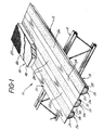
- a roof structure system 10 of the present invention is shown in Fig. 1 as including a fluted metal deck 12 supported on a superstructure member 14 of a building (not shown).
- the fluted metal deck 12 and superstructure member 14 are typical of decks and superstructures used in commercial buildings such as factories, shopping centers, warehouses and the like.
- the fluted metal deck 12 is preferably mounted to the superstructure member 14 by welding.
- the fluted metal deck 12 includes a lower or bottom surface 18 and an upper or top surface 20. As viewed from top surface 20, the fluted metal deck 12 includes a series of parallel, longitudinally extending, generally planar crests 24. A series of longitudinally extending trapazoidal troughs 26 are disposed between the crests 24 and are generally parallel thereto. The troughs 26 include a generally planar bottom surface 28 and a pair of angled sidewalls 30 and 32.
- Strips 36 of non-flammable, absorbent material are placed in each of the troughs 26 and, in the embodiment of Fig. 1, extend along the entire length of each trough 26.
- each strip 36 fills the trough up to the top of the sidewalls 30, 32 such that the cross-sectional area of each strip 36 is generally equal to the cross-sectional area of the trough 26 in which the strip 36 is placed.
- a layer of meltable, thermoplastic insulation material 40 overlays the metal deck 12.
- the underside surface of the insulation material 40 is preferably placed directly on the upper surface 20 of the metal deck 12 so that the insulation material 40 rests on the crests 24 and spans the troughs 26 of the metal deck 12. Although only a small section of the insulation material 40 is shown in the figures, the insulation material 40 will generally overlay the entire metal deck 12.
- a layer of water impermeable material 46 may overlay the upper surface 48 of the insulation layer 40.
- the water impermeable material seals the roof to prevent the intrusion of moisture.
- ballast material 50 (here shown as gravel) is preferably placed over the water impermeable layer 46.
- the ballast layer 50 provides additional weight on the roof to help prevent the components of the roof from becoming dislodged in heavy winds.
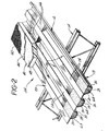
- FIG. 2 An alternate embodiment of the present invention is shown in Fig. 2.
- the deck 12, superstructure 14, insulation layer 40, water impermeable layer 46 and ballast layer 50 are similar to those shown in Fig. 1.
- Fig. 2 shows an alternate embodiment in terms of the absorbent strips.
- the absorbent strips shown in Fig. 2 each comprise a pair of discrete, spatially separated strip segments 64 and 66.
- Each strip segment 64, 66 has a cross-sectional area generally equal to the cross-sectional area of the trough 26 in which it is placed and has a length of preferably between 1 and 6 inches (2.5 and 15 cm) long and most preferably between 3 and 6 inches (7.5 and 15 cm) long.
- the strip segments 64, 66 of each strip are preferably spaced apart approximately 2 to 10 feet (0.6 to 3 m). The length of the strip segments 64, 66 should be greater than the width of the troughs 26 in which the segments 64, 66 are placed.
- strip segments in adjacent troughs are aligned to form an array wherein strip segments 64 form a linear row extending generally perpendicular to the longitudinal extent of the troughs 26, and strip segments 66 form a linear row extending perpendicular to the longitudinal extent of troughs 26.
- metal deck 12 The choice of material used in the fabrication of the metal deck 12 is determined by factors such as the strength, weight, and cost of the material, ease of fabrication, resistance to corrosion and flammability.
- metal decks 12 for commercial and industrial buildings are fabricated from either steel or aluminum.
- the metal deck 12 of a typical building will comprise a plurality of interfitted metal deck panels which are joined by riveting, welding or the like. Notwithstanding the care taken in joining the panels together, the seams at which the metal panels are joined are usually not leakproof. Thus, the seams can provide a path through which molten insulation material can travel into the interior of a building during a fire. Additionally, the high temperatures experienced by the panels can cause the seams to come apart, thus increasing the flow of molten insulation material into the interior of a burning building.
- troughs 26 and crests 24 of the metal deck 12 shown in the figures have a generally trapazoidal cross-sectional shape, it will be appreciated that metal decks can be utilized having a wide variety of other cross-sectional shapes.
- the ideal material from which to fabricate the absorbent strips 36 or strip segments 64, 66 is a non-combustible, relatively inexpensive, inert granular inorganic material, which can absorb hydrophobic materials such as molten thermoplastic insulation. Additionally, the material should be capable of being packed in the troughs 26 to have a relatively low permeability to molten thermoplastic materials so that the molten material will flow through the absorbent strip 36, and strip segments 64, 66 (if at all) at a relatively slow rate.
- absorbent strip material examples include sand, gypsum, fly ash, vermiculite, glass fibers, expandable shale, expandable clay, iron ore slag, firestop caulking, crushed glass, cement powder, crushed shells, pea gravel, epsom salts and crushed rocks.
- expandable shale and expandable clay are most preferred because of their ability to absorb molten thermoplastic material and their ability to expand to occupy available space in the trough.
- the absorbent strips 36 and strip segments 64, 66 generally do not include backing materials or binders. Rather, the absorbent material is poured directly into the trough 29. Due to the fact that most of roof structures with which the present invention is utilized are flat, or sloped only slightly, a loose packed absorbent will generally maintain its position in the trough without the positional shifting which might occur in roofs having a greater pitch.
- the absorbent material should be placed in the troughs 26 so that the top of the absorbent material is generally co-planar with the crests 24. By making the absorbent material flush with the crests 24, gases formed by vaporized insulation material are prevented from flowing in the troughs by passing between the absorbent strip 36 and the underside surface of the insulation layer 40. However, the crest 24, should be free of absorbent material to provide a smooth, planar surface upon which the thermoplastic insulation material 40 can rest.
- the best method for applying the absorbent strips 36 and strip segments 64, 66 is by the use of a device similar to a gravel spreader having a high enough flow rate to fill the troughs 26 with absorbent material.
- the same absorbent materials as those used for the embodiment of Fig. 1 can be used.
- the length of the strip segments 64, 66 should be great enough to ensure that the apex of the segment will remain generally co-planar with the crest 24 after the absorbent materials in the strip segments 64, 66 have settled.
- the segments 64, 66 are illustrated in Fig. 2 as being block shaped, the segments 64, 66 can have a truncated, pyramid-like shape.
- the strip segments 64, 66 are arranged in rows extending generally perpendicular to the longitudinal extent of the troughs 26. Through this arrangement, the segments help to compartmentalize the roof and thus help to contain the spread of the fire between various compartments.
- the segments 64, 66 can be placed at various positions on the deck 12, they are preferably placed at least in the areas of the metal deck above the seams adjoining adjacent panels of the deck.
- the spacing between rows of segments 64, 66 is largely dependent on the size of the panels used for the metal deck 12. For example, if an eight foot (2.4 m) panel (as measured in a direction parallel to the longitudinal extent of the troughs 26) is used, the spacing between adjacent rows of segments 64, 66 would be no more than eight feet (2.4 m) apart so that the segments 64, 66 could be placed above the seams joining adjacent panels. Preferably, a row of strip segments would also be placed intermediate the rows of segments over the seams, thus yielding a spacing of four feet (1.2 m) between adjacent rows.
- the amount of absorbent material used on a particular roof is largely dependent on the thickness of the insulation.
- a relatively greater amount of absorbent material is used when the insulative layer 40 is relatively thick (e.g. 8 inches; 20 cm); and a relatively lesser amount of absorbent material is used when the insulative layer is relatively thin (e.g. 2 inches; 5 cm).
- the amount of absorbent material used can be varied by varying either the length of the strip segments 64, 66 or the spacing between segment rows.
- thermoplastic foams can be used for insulative layer 40.
- the considerations used in determining which type of foam to use are based on factors such as insulative capacity of a particular foam, weight, cost, melting point, and availability.
- the plastic foam used in the present invention should have a density of between 0.25 and 4 lbs/ft3 (0.5 to 6.5 kg/m3).
- thermoplastic foams include extruded polystyrene foams, molded bead polystyrene foams, polyurethane foam, polyvinyl chloride foam, and some thermoplastic polyisocyanate foams.
- the insulation material 40 is formed in sheet-like blocks having a thickness of generally between 1 and 8 inches (2.5 to 20 cm), and preferably 3 inches thick (7.5 cm), a width of either 2 feet (.6 m) or 4 feet (1.2 m) and a length of 8 feet (2.4 m).
- the panels which comprise the insulative layer 40 can be clipped together or attached to the metal deck 12 to help the panels maintain their proper positioning.
- the water impermeable layer 46 comprises a sheet membrane which may be made of either a thermosetting plastic or a thermoplastic material.
- a sheet membrane which may be made of either a thermosetting plastic or a thermoplastic material.
- examples of such materials for use as sheet membranes include ethylene propylene diene monomer (EPDM), polyvinyl chloride (PVC), chlorinated polyethylene (CPE), chlorosulfonated polyethylene (CSPE), polyisobutylene (PIB), and chlorinated polyvinyl acrylonitrile (CPA).
- EPDM ethylene propylene diene monomer
- PVC polyvinyl chloride
- CPE chlorinated polyethylene
- CSPE chlorosulfonated polyethylene
- PIB polyisobutylene
- CPA chlorinated polyvinyl acrylonitrile
- the sheet membrane of water impermeable material is dispensed on rolls generally having a width of 3 to 10 feet (1 to 10 m) and a thickness
- the ballast layer 50 preferably comprises a gravel, such as ASTM No. 4 stone having an average diameter of between 1.25 and 1.5 inches (3.2 and 3.8 cm).
- the No. 4 stone is placed on top of the water impermeable layer 46 to a depth of approximately 1 1/2 to 2 inches (3.8 to 5 cm) to achieve a ballast weight of about 10 lb/ft2 (50 kg/m2).
- the ballast 50 protects the underlying roof components from ultraviolet radiation and provides resistance to wind and buoyancy. Therefore, the amount of ballast 50 placed on the roof should be sufficient to achieve the above objectives without placing undue stress on the structural components of the roof.
- a sand and cement mixture can be used as the ballast layer. Such a sand and cement layer would typically have a thickness of between 0.75 and 4 inches (1.9 and 10 cm).
- the fire retardant of the present invention helps to prevent the spread of fire in an underdeck fire situation in the following manner.
- the heat from a fire burning in the interior of the building causes the metal deck 12 to become heated.
- the metal deck 12 conducts the heat to the thermoplastic insulation layer 40. If enough heat is applied to the thermoplastic insulation layer, the thermoplastic insulation layer 40 will eventually begin to melt from the bottom up.
- the insulation layer 40 is likely to melt from the bottom up because the bottom surface of the insulation layer 40 is the surface which is in contact with the crests 24 of the heated metal deck 12. As the insulation layer 40 begins its melting process, three events will occur at about the same time.
- the first event involves the formation of molten and vaporous thermoplastic material along the bottom surface of the thermal insulation layer 40. This molten or vaporous material will tend to flow downwardly into troughs 26.
- this molten and vaporous material will be absorbed by the absorbent strips 36 as it flows into the troughs 26, thus retarding the flow of the molten vaporous material along the troughs 26.
- the vaporous and molten thermoplastic material is less likely to be able to find its way to a seam, joint or crack in the deck 12 through which it can pass into the interior of the building.
- the molten or vaporous material will flow into the trough 26, and along the trough 26 to a point wherein it encounters one of the strip segments 64, 66.
- the molten material will be both absorbed and dammed by the segments 64, 66, thus retaining the material within the compartment formed between adjacent segments 64, 66 and retarding the flow of the material past the segments 64, 66.
- thermoplastic insulation material 40 melts, it absorbs heat from the metal deck 12. By absorbing heat from the metal deck 12, the insulation material 40 serves as a heat sink and keeps the metal deck 12 relatively cooler.
- thermoplastic insulation material 40 The third event which occurs during the melting of the thermoplastic insulation material 40, is that the foam cells of the thermoplastic insulation material 40 tend to collapse as the thermoplastic insulation material 40 melts. This collapse of the cells permits the gravel of the ballast layer 50 to penetrate into the thermoplastic insulation material 40. This penetration of the gravel into the thermoplastic insulation layer 40 causes the gravel to form a firewall-like enclosure around the roof, thereby impeding the flow of oxygen into the interior of the building.
- the instant invention provides a means for utilizing thermoplastic insulation to form a relatively fire-resistant roof structure.
Landscapes
- Engineering & Computer Science (AREA)
- Architecture (AREA)
- Civil Engineering (AREA)
- Structural Engineering (AREA)
- Building Environments (AREA)
- Roof Covering Using Slabs Or Stiff Sheets (AREA)
Applications Claiming Priority (2)
| Application Number | Priority Date | Filing Date | Title |
|---|---|---|---|
| US909352 | 1986-09-19 | ||
| US06/909,352 US4747247A (en) | 1986-09-19 | 1986-09-19 | Roof system |
Publications (2)
| Publication Number | Publication Date |
|---|---|
| EP0260911A2 true EP0260911A2 (de) | 1988-03-23 |
| EP0260911A3 EP0260911A3 (de) | 1989-09-06 |
Family
ID=25427092
Family Applications (1)
| Application Number | Title | Priority Date | Filing Date |
|---|---|---|---|
| EP87308100A Withdrawn EP0260911A3 (de) | 1986-09-19 | 1987-09-14 | Dachsystem |
Country Status (5)
| Country | Link |
|---|---|
| US (1) | US4747247A (de) |
| EP (1) | EP0260911A3 (de) |
| JP (1) | JPS63103143A (de) |
| AU (1) | AU587910B2 (de) |
| CA (1) | CA1289715C (de) |
Cited By (5)
| Publication number | Priority date | Publication date | Assignee | Title |
|---|---|---|---|---|
| RU2117121C1 (ru) * | 1996-12-04 | 1998-08-10 | Акционерное общество открытого типа по наладке, совершенствованию технологии и эксплуатации электростанций и сетей "Уралтехэнерго" | Способ повышения пожаро-взрывобезопасности кровельных покрытий (варианты) и конструкция кровли |
| EP0898628A4 (de) * | 1996-05-14 | 2001-02-28 | Owens Corning Fiberglass Corp | Verfahren zum isolieren von metallplattendachkonstruktionen |
| EP1739246A1 (de) * | 2005-06-30 | 2007-01-03 | United States Gypsum Company | Bodensystem mit stahlen Wellplatten und akoestischen Elementen |
| EP3467230A1 (de) * | 2017-10-06 | 2019-04-10 | HILTI Aktiengesellschaft | Baugruppe mit profilblech und brandschutz- und oder schallschutzelement sowie brandschutz- und /oder schallschutzelement zur bildung einer baugruppe |
| CN112343264A (zh) * | 2020-10-09 | 2021-02-09 | 上海宏诺建筑科技有限公司 | 一种无冷桥无声桥的防水抗风屋面系统的构造方法 |
Families Citing this family (23)
| Publication number | Priority date | Publication date | Assignee | Title |
|---|---|---|---|---|
| FR2619584B1 (fr) * | 1987-08-17 | 1989-12-01 | Jacob Christian | Couvre-sol de proprete s'opposant a la vegetation des sols |
| US4996812B1 (en) * | 1990-02-20 | 1999-11-02 | Carlisle Corp | Method of membrane application in roof construction |
| US5787668A (en) * | 1996-03-11 | 1998-08-04 | Siplast, Inc. | Ventilated insulated roofing system with improved resistance to wind uplift |
| US5950383A (en) * | 1997-07-09 | 1999-09-14 | Bridgestone Corporation | Metal roof sealing system and method |
| US6256957B1 (en) * | 1998-08-10 | 2001-07-10 | Thomas L. Kelly | Scrim reinforced lightweight concrete roof system |
| US6427404B1 (en) * | 1998-12-22 | 2002-08-06 | Palisades Atlantic Corporation | Base sheet for retrofitting existing roofing |
| US6742313B2 (en) * | 2001-03-15 | 2004-06-01 | R.S. Associates, Inc. | Non-cellular adhesive for composite roof structure |
| US6679018B2 (en) * | 2002-02-01 | 2004-01-20 | Chem Link, Inc. | Roofing system and method |
| AU2003903054A0 (en) * | 2003-06-17 | 2003-07-03 | Higgins, Ian John | Building construction elements |
| US8104247B2 (en) * | 2003-11-12 | 2012-01-31 | Margaret Henderson Hasse | Disposable roof covering |
| NL1026388C2 (nl) * | 2004-06-11 | 2005-12-15 | O & P Res And Dev | Werkwijze voor het vervaardigen van een bouwconstructie, alsmede bekisting daarvoor. |
| US8567144B2 (en) * | 2004-09-14 | 2013-10-29 | Thomas L. Kelly | Low cost roof system and method of constructing the same |
| US20070234669A1 (en) * | 2006-02-16 | 2007-10-11 | Henry Gembala | Roof system |
| US20070251350A1 (en) * | 2006-04-29 | 2007-11-01 | Bryan Henry H Iii | High Temperature and Vibration Joint Closure Composition and Method of Application |
| US8033073B1 (en) * | 2007-09-27 | 2011-10-11 | Steven Binder | Roof batten system |
| JP2011510199A (ja) * | 2008-01-23 | 2011-03-31 | ダウ グローバル テクノロジーズ インコーポレイティド | 外側蒸気透過性フォーム断熱材を含有する建築構造体 |
| US20090223159A1 (en) * | 2008-03-08 | 2009-09-10 | Mark Colon | Firestop block and thermal barrier system for fluted metal decks |
| US7845090B2 (en) * | 2008-04-24 | 2010-12-07 | Ruppe Iii John P | Template for cutting wall board to fit fluted deck ceilings |
| US7673394B2 (en) * | 2008-04-24 | 2010-03-09 | Ruppe Iii John P | Template for cutting wall board to fit fluted deck ceilings |
| US8327605B1 (en) * | 2008-07-29 | 2012-12-11 | Binder Revocable Trust | Roof batten system |
| US10400451B2 (en) | 2009-10-16 | 2019-09-03 | Donal Curtin | Composite panel |
| RU2014153016A (ru) * | 2012-06-07 | 2016-07-27 | ДАУ ГЛОБАЛ ТЕКНОЛОДЖИЗ ЭлЭлСи | Система изоляции стены пенопластом |
| US12116782B2 (en) * | 2022-08-04 | 2024-10-15 | Tate Access Floors, Inc. | Pre-assembled decking panel and strut assembly for data center ceilings and roofs |
Family Cites Families (9)
| Publication number | Priority date | Publication date | Assignee | Title |
|---|---|---|---|---|
| US2106390A (en) * | 1936-06-02 | 1938-01-25 | Norman E Crane | Building board |
| US2616283A (en) * | 1946-05-03 | 1952-11-04 | Branstrator | Building unit |
| US3466222A (en) * | 1967-07-26 | 1969-09-09 | Lexsuco Inc | Fire retardant insulative structure and roof deck construction comprising the same |
| BE786217A (fr) * | 1971-07-14 | 1973-01-15 | Dow Chemical Co | Element de toiture et son procede de fabrication |
| US3763605A (en) * | 1972-06-30 | 1973-10-09 | Freeman Ltd W | Roofing system and method of application |
| US4073997A (en) * | 1974-12-06 | 1978-02-14 | Owens-Corning Fiberglas Corporation | Composite panel |
| US3971184A (en) * | 1975-03-05 | 1976-07-27 | Robert M. Barlow | Insulated, water impermeable roofing system |
| US4449336A (en) * | 1980-06-19 | 1984-05-22 | Kelly Thomas L | Fire barrier reservoir |
| DE3409897A1 (de) * | 1984-03-17 | 1985-09-19 | August Wilhelm Andernach Kg | Brandschutzbahn mit dampfsperre |
-
1986
- 1986-09-19 US US06/909,352 patent/US4747247A/en not_active Expired - Lifetime
-
1987
- 1987-09-10 AU AU78237/87A patent/AU587910B2/en not_active Ceased
- 1987-09-14 EP EP87308100A patent/EP0260911A3/de not_active Withdrawn
- 1987-09-18 CA CA000547253A patent/CA1289715C/en not_active Expired - Fee Related
- 1987-09-18 JP JP62232706A patent/JPS63103143A/ja active Granted
Cited By (6)
| Publication number | Priority date | Publication date | Assignee | Title |
|---|---|---|---|---|
| EP0898628A4 (de) * | 1996-05-14 | 2001-02-28 | Owens Corning Fiberglass Corp | Verfahren zum isolieren von metallplattendachkonstruktionen |
| RU2117121C1 (ru) * | 1996-12-04 | 1998-08-10 | Акционерное общество открытого типа по наладке, совершенствованию технологии и эксплуатации электростанций и сетей "Уралтехэнерго" | Способ повышения пожаро-взрывобезопасности кровельных покрытий (варианты) и конструкция кровли |
| EP1739246A1 (de) * | 2005-06-30 | 2007-01-03 | United States Gypsum Company | Bodensystem mit stahlen Wellplatten und akoestischen Elementen |
| US7908810B2 (en) | 2005-06-30 | 2011-03-22 | United States Gypsum Company | Corrugated steel deck system including acoustic features |
| EP3467230A1 (de) * | 2017-10-06 | 2019-04-10 | HILTI Aktiengesellschaft | Baugruppe mit profilblech und brandschutz- und oder schallschutzelement sowie brandschutz- und /oder schallschutzelement zur bildung einer baugruppe |
| CN112343264A (zh) * | 2020-10-09 | 2021-02-09 | 上海宏诺建筑科技有限公司 | 一种无冷桥无声桥的防水抗风屋面系统的构造方法 |
Also Published As
| Publication number | Publication date |
|---|---|
| CA1289715C (en) | 1991-10-01 |
| EP0260911A3 (de) | 1989-09-06 |
| US4747247A (en) | 1988-05-31 |
| AU587910B2 (en) | 1989-08-31 |
| JPH0449613B2 (de) | 1992-08-12 |
| JPS63103143A (ja) | 1988-05-07 |
| AU7823787A (en) | 1988-03-24 |
Similar Documents
| Publication | Publication Date | Title |
|---|---|---|
| US4747247A (en) | Roof system | |
| US4120131A (en) | Building structure | |
| US4274239A (en) | Building structure | |
| US4507901A (en) | Sheet metal structural shape and use in building structures | |
| US4114335A (en) | Sheet metal structural shape and use in building structures | |
| US4719723A (en) | Thermally efficient, protected membrane roofing system | |
| US4090336A (en) | Insulated roofing structure | |
| US3411256A (en) | Roof construction and method thereof | |
| US4189886A (en) | Ventilated insulated roofing system | |
| US6694693B2 (en) | Insulation block for roof structure | |
| US4559263A (en) | Cement-foam composite board | |
| US5950383A (en) | Metal roof sealing system and method | |
| US4351138A (en) | Roof construction and method thereof | |
| NO136654B (de) | ||
| US4601943A (en) | Fire proofing web with vapor barrier | |
| US4572857A (en) | Insulating board of composite material | |
| US3962841A (en) | Insulated decking structure and method | |
| CA1051682A (en) | Building deck construction | |
| US4267678A (en) | Insulated roof structure | |
| USRE31007E (en) | Roof construction and method thereof | |
| US3965641A (en) | Sheet metal structural shape and use in insulated decking structure and method | |
| RU242958U1 (ru) | Кровля | |
| US2848957A (en) | Fire-retaining roof structure | |
| JPH09310452A (ja) | 屋根用断熱パネル | |
| RU2576266C1 (ru) | Панель поэлементной сборки с фальцевым покрытием |
Legal Events
| Date | Code | Title | Description |
|---|---|---|---|
| PUAI | Public reference made under article 153(3) epc to a published international application that has entered the european phase |
Free format text: ORIGINAL CODE: 0009012 |
|
| AK | Designated contracting states |
Kind code of ref document: A2 Designated state(s): AT BE DE FR GB GR IT NL |
|
| PUAL | Search report despatched |
Free format text: ORIGINAL CODE: 0009013 |
|
| AK | Designated contracting states |
Kind code of ref document: A3 Designated state(s): AT BE DE FR GB GR IT NL |
|
| 17P | Request for examination filed |
Effective date: 19900227 |
|
| 17Q | First examination report despatched |
Effective date: 19910404 |
|
| STAA | Information on the status of an ep patent application or granted ep patent |
Free format text: STATUS: THE APPLICATION IS DEEMED TO BE WITHDRAWN |
|
| 18D | Application deemed to be withdrawn |
Effective date: 19931203 |
|
| RIN1 | Information on inventor provided before grant (corrected) |
Inventor name: PETRASH, GORDON P. Inventor name: RILEY, ELIZABETH A. Inventor name: ROODVOETS, DAVID L. Inventor name: PETERSEN, WAYNE E., JR. |