EP0260917B1 - Imprimante thermique par transfert - Google Patents
Imprimante thermique par transfert Download PDFInfo
- Publication number
- EP0260917B1 EP0260917B1 EP87308116A EP87308116A EP0260917B1 EP 0260917 B1 EP0260917 B1 EP 0260917B1 EP 87308116 A EP87308116 A EP 87308116A EP 87308116 A EP87308116 A EP 87308116A EP 0260917 B1 EP0260917 B1 EP 0260917B1
- Authority
- EP
- European Patent Office
- Prior art keywords
- data
- bar code
- current
- thermal head
- printing
- Prior art date
- Legal status (The legal status is an assumption and is not a legal conclusion. Google has not performed a legal analysis and makes no representation as to the accuracy of the status listed.)
- Expired - Lifetime
Links
Images



Classifications
-
- B—PERFORMING OPERATIONS; TRANSPORTING
- B41—PRINTING; LINING MACHINES; TYPEWRITERS; STAMPS
- B41J—TYPEWRITERS; SELECTIVE PRINTING MECHANISMS, i.e. MECHANISMS PRINTING OTHERWISE THAN FROM A FORME; CORRECTION OF TYPOGRAPHICAL ERRORS
- B41J2/00—Typewriters or selective printing mechanisms characterised by the printing or marking process for which they are designed
- B41J2/315—Typewriters or selective printing mechanisms characterised by the printing or marking process for which they are designed characterised by selective application of heat to a heat sensitive printing or impression-transfer material
- B41J2/32—Typewriters or selective printing mechanisms characterised by the printing or marking process for which they are designed characterised by selective application of heat to a heat sensitive printing or impression-transfer material using thermal heads
- B41J2/35—Typewriters or selective printing mechanisms characterised by the printing or marking process for which they are designed characterised by selective application of heat to a heat sensitive printing or impression-transfer material using thermal heads providing current or voltage to the thermal head
- B41J2/355—Control circuits for heating-element selection
- B41J2/36—Print density control
- B41J2/365—Print density control by compensation for variation in temperature
-
- B—PERFORMING OPERATIONS; TRANSPORTING
- B41—PRINTING; LINING MACHINES; TYPEWRITERS; STAMPS
- B41J—TYPEWRITERS; SELECTIVE PRINTING MECHANISMS, i.e. MECHANISMS PRINTING OTHERWISE THAN FROM A FORME; CORRECTION OF TYPOGRAPHICAL ERRORS
- B41J2/00—Typewriters or selective printing mechanisms characterised by the printing or marking process for which they are designed
- B41J2/315—Typewriters or selective printing mechanisms characterised by the printing or marking process for which they are designed characterised by selective application of heat to a heat sensitive printing or impression-transfer material
- B41J2/32—Typewriters or selective printing mechanisms characterised by the printing or marking process for which they are designed characterised by selective application of heat to a heat sensitive printing or impression-transfer material using thermal heads
- B41J2/325—Typewriters or selective printing mechanisms characterised by the printing or marking process for which they are designed characterised by selective application of heat to a heat sensitive printing or impression-transfer material using thermal heads by selective transfer of ink from ink carrier, e.g. from ink ribbon or sheet
-
- B—PERFORMING OPERATIONS; TRANSPORTING
- B41—PRINTING; LINING MACHINES; TYPEWRITERS; STAMPS
- B41J—TYPEWRITERS; SELECTIVE PRINTING MECHANISMS, i.e. MECHANISMS PRINTING OTHERWISE THAN FROM A FORME; CORRECTION OF TYPOGRAPHICAL ERRORS
- B41J2/00—Typewriters or selective printing mechanisms characterised by the printing or marking process for which they are designed
- B41J2/315—Typewriters or selective printing mechanisms characterised by the printing or marking process for which they are designed characterised by selective application of heat to a heat sensitive printing or impression-transfer material
- B41J2/32—Typewriters or selective printing mechanisms characterised by the printing or marking process for which they are designed characterised by selective application of heat to a heat sensitive printing or impression-transfer material using thermal heads
- B41J2/35—Typewriters or selective printing mechanisms characterised by the printing or marking process for which they are designed characterised by selective application of heat to a heat sensitive printing or impression-transfer material using thermal heads providing current or voltage to the thermal head
- B41J2/355—Control circuits for heating-element selection
- B41J2/36—Print density control
Definitions
- the present invention generally relates to thermal transfer type printers, and more particularly to a thermal transfer type printer capable of varying a printing density thereof based on printing data which select desirable printing density.
- a thermal transfer type printer prints bar codes, characters and graphics on a printing paper by use of a transfer ribbon and a line thermal head (hereinafter, referred to as a thermal head). More specifically, thermal melting ink is painted on a surface of the transfer ribbon so that an ink layer is formed on the surface of the transfer ribbon, and this ink layer of the transfer ribbon is pressed against the printing paper. The thermal head is pressed against the backside of the transfer ribbon and heated so as to melt the thermal melting ink of the ink layer in response to a desirable pattern. Such melted ink is transferred on the printing paper. Thus, the desirable pattern is printed on the printing paper.
- a thermosensitive type printer is also well known. In such thermosensitive type printer, a printing pattern is directly given to a thermosensitive paper so that the printing pattern is printed on the thermosensitive paper.
- the printing density is generally set to a predetermined fixed density by use of a volume-type control and a switch.
- a density control circuit is provided for maintaining a high printing quality. More specifically, the density control circuit controls a heating temperature of the thermal head based on the present temperature of the thermal head detected by a thermistor so that the printing density is maintained at the predetermined fixed density.
- this density control circuit provides a memory (e.g., ROM) therein, which is written by data concerning a current-on time (i.e., a period for supplying the current to the thermal head). As shown in Fig.
- this current-on times are estimated from current-on characteristics (shown as a curve for supplied energy) which determine a value of a current supplied to the thermal head.
- the respective data of the current-on times obtained from the above curve (shown in Fig. 1) will be shown in the following Table 1.
- a period for supplying the current to the thermal head is determined. For example, in the case where a printing operation must be started immediately after a power switch of a printer is turned on, the current-on time is set relatively longer because an initial temperature of the thermal head is relatively low. When the initial temperature of the thermal head is set at 0 degree centigrade, it is apparent from Fig. 1 that the desirable current-on time is 3 ms (i.e., 3 millisecond). On the contrary, when the temperature of the thermal head rises to a sufficiently high temperature, the current-on time can be shorter. For example, when the temperature of the thermal head is at 60 degrees centigrade, the desirable current-on time is 0.5 ms. As described above, the density control circuit detects the temperature of the thermal head by the thermistor (which is provided within the thermal head) and determines the desirable current-on time where the printing density is controlled to become constant.
- the thermistor which is provided within the thermal head
- the conventional thermal transfer type printers include a bar code printer and a color printer and the like.
- bar code printer is used in several fields, such as a factory automation (FA) field, a distribution industry field and the like.
- FA factory automation
- OA office automation
- CAD computer aided design
- the printing density is maintained constant in the conventional thermal transfer type printer, regardless of kinds of the printing density.
- the conventional printer suffers a problem in that it is impossible for an external control device (such as a computer etc.) to vary the printing density in accordance with character patterns.
- a variable density switch enables the printer to vary the printing density of all printed patterns. Even in the printer having such a variable density switch, however, it is impossible to vary the printing density by every character data.
- the horizontal bar codes differ from the vertical bar codes by a reading direction of the bar code reader. More specifically, data of the horizontal bar codes can be read by the bar code reader in a horizontal direction, and data of the vertical bar codes can be read by the bar code reader in a vertical direction.
- Figs. 2A, 2B, 3A and 3B show printed dots of the thermal transfer type bar code printer. More specifically, Figs. 2A and 2B show horizontal bar codes which are read by the bar code reader in the horizontal direction indicated by an arrow H, and Figs. 3A and 3B show vertical bar codes which are read by the bar code reader in the vertical direction indicated by an arrow V.
- Fig. 2A designates the horizontal bar codes in the case where the current-on time of the thermal head is set relatively short. As shown in Fig. 2A, the printing density is therefore faint and a distance A is formed between two adjacent dots. This horizontal bar code must be formed in a continuous line, however, the horizontal bar code is actually formed in a dotted line. On the contrary, in the case where the current-on time of the thermal head is set relatively long as shown in Fig. 2B in order to prevent the above phenomenon, sizes of dots become large and the two adjacent dots are connected together so that the horizontal bar code is formed in the continuous line.
- Fig. 3A designates vertical bar codes in the case where the current-on time of the thermal head is set relatively long. As shown in Fig. 3A, the printing density of the vertical bar codes becomes deep so that two adjacent vertical bar codes are connected by overflow ink. This phenomenon is called "tailing" phenomenon. In order to prevent such tailing phenomenon from occurring, the current-on time of the thermal head must be set short so as to make the sizes of dots small as shown in Fig. 3B.
- EP-A-0193343 discloses a two-colour printing operation in which the current-on time is controlled to energise heating elements of a thermal head, thereby emphasising specific information printed in a particular colour.
- EP-A-0197549 discloses a thermal head temperature control device in which the electrical power supply to the thermal head is controlled in accordance with printing conditions.
- a thermal transfer type bar code printer for printing a desired printing pattern on a printing paper by use of a thermal head which said printing paper is carried in a predetermined carrying direction
- said printer comprising: (a) an input terminal supplied with a select signal for selecting one of a vertical bar code and a horizontal bar code, the select signal being supplied from an external device, the vertical bar code being identical to a bar code which is printed on the printing paper in a direction perpendicular to the carrying direction of the printing paper, the horizontal bar code being identical to a vertical bar code which is printed on the printing paper in the carrying direction of the printing paper; (b) a plurality of memory portions for storing control data for controlling a power supplied to the thermal head, the control data representing a specific power supply characteristics, the control data stored in a certain memory portion being different from those stored in other memory portions; (c) a power supply selecting portion for selecting one of the memory portions, the memory portion storing the control data which represent a relatively large quantity of power supply being selected when the
- a thermal transfer type printer comprising: (a) a first memory portion for temporarily storing density increment/decrement data supplied from an external device; (b) a second memory portion for storing reference data concerning a reference quantity of power supplied to the thermal head; (c) an operation portion for increasing or decreasing the value of the reference data by a density data value which is obtained from the density increment/decrement data stored in the first memory portion; and (d) current-on control means for controlling a quantity of power supplied to the thermal head based on an operation result of the operation portion.
- Fig. 4 is a mechanical diagram showing an embodiment of a constitution of a thermal transfer type bar code printer according to the present invention.
- 1 designates a transfer ribbon, the upper surface of which is painted with thermal melting ink.
- This transfer ribbon 1 is transmitted from a supply reel 2 and is passed through a printing portion 3, and thereafter, the transfer ribbon 1 is taken up by a take-up reel 4.
- 5 designates a printing paper, one surface of which is pressed against and touched together with the upper surface of the transfer ribbon 1.
- This printing paper 5 piled with the transfer ribbon 1 is passed through the printing portion 3.
- the printing portion 3 consists of a thermal head 6 and a platen roller 7.
- the thermal head 6 provides heating cells (which will be described later) which are heated by supplying currents thereto.
- the thermal head 6 When the printing operation is performed, the thermal head 6 is forced to be pressed against the platen roller 7, so that the transfer ribbon 1 and the printing paper 5 are piled together under the pressure applied between the thermal head 6 and the platen roller 7. In this case, the heated heating cells melt the ink painted on the transfer ribbon 1 and the melted ink is transferred to the printing paper 5. Furthermore, the platen roller 7 revolves by a minute distance in a direction Y, so that the transfer ribbon 1 and the printing paper 5 can advance by every dots. The heating temperature of the thermal head 6 can be measured by a thermistor 8 mounted on the thermal head 6.
- Fig. 5 is a block diagram showing an electric connection of the printer shown in Fig. 4.
- 10 designates a temperature detecting circuit which is constituted by an analog-to-digital (A/D) converter 9 and the thermistor 8.
- the analog output signal of the thermistor 8 is converted into digital data in the A/D converter 9.
- This digital data are supplied to a control portion 11 as temperature data, the value of which represents the temperature of the thermal head 6.
- An interface circuit 12 is inserted to transfer several kinds of data between an external computer (not shown) and the control portion 11.
- Such data include print data DA, a control signal ESCH for printing the horizontal bar codes and a control signal ESCV for printing the vertical bar codes.
- control portion 11 consists of a central processing unit (CPU), a work memory and a program memory (not shown) and the like.
- This control portion 11 controls several portions within the printer and supplies current-on time data TD to a current-on control circuit 17 in order to determine the current-on time for the thermal head 6.
- Such current-on time data TD are stored as a table in a current-on time data memory 15 (hereinafter, referred simply as to a memory 15).
- a memory 15 hereinafter, referred simply as to a memory 15.
- the control portion 11 reads optimum current-on time data TD from the memory 15 in accordance with several kinds of required conditions.
- Fig. 6 shows curves of supplied energy, the data of which are stored in the memory 15.
- a x-axis represents the current-on time
- a y-axis represents a surrounding temperature of the thermal head 6.
- Two curves AV and BH are shown in Fig. 6, and the supplied energy on the curve BH is higher than that of the curve AV.
- the data of these two curves are stored in the memory 15 as numeric value table etc.
- the curve BH represents the optimum printing density for printing the horizontal bar codes, and the data of such printing density are pre-obtained in an experiment on the current-on time characteristics of the thermal head.
- the curve AV represents the optimum printing density for printing the vertical bar codes.
- the control portion 11 selects the data of the curve AV when the signal ESCV is supplied thereto.
- the control portion 11 selects the data of the curve BH when the signal ESCH is supplied thereto.
- a current-on time t1 is read from the curve AV
- a current-on time t2 is read from the curve BH.
- the control portion 11 determines the current-on time data TD based on the temperature data from the temperature detecting circuit 10 and selected one of the curves AV and BH.
- the data stored in the memory 15 are read out based on address data ADR which are renewed by every data read-out timings in the control portion 11. For example, the upper data within the address data ADR are determined by one of the signals ESCH and ESCV, and the lower data within the address data ADR are determined by the temperature data from the temperature detecting circuit 10.
- 13 designates a motor drive circuit which drives a step motor 14 so as to revolve the platen roller 7 by a predetermined step distance under the control of the control portion 11.
- 16 designates a print data memory which stores dot data (which represent dot patterns of the bar codes) supplied from the external computer (not shown) and the like. The dot data are read out from the print data memory 16 based on the address data ADR supplied from the control portion 11 and such dot data are supplied to a head drive circuit 18.
- the current-on control circuit 17 supplies the currents to the selected heating cells for a period corresponding to the current-on time data TD. As shown in Fig.
- this current-on time control circuit 17 consists of a programmable timer 17a and AND gates AN1 to AN n .
- the current-on time data TD are preset in the programmable timer 17a by the control portion 11.
- the one input terminals of the AND gates AN1 to AN n are connected in common to the output terminal of the programmable timer 17a, and common signals C1 to C n outputted from the control portion 11 are supplied respectively to other input terminals of the AND gates AN1 to AN n .
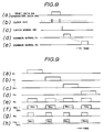
- These common signals C1 to C n have the same constant pulse width, and the leading edge timings of such common signals C1 to C n are sequentially shifted by a predetermined time as shown in Figs. 8(d) and 8(e).
- the head drive circuit 18 supplies the currents to heating cells TH1 to THn within the thermal head 6 in correspondence with the dot data supplied from the print data memory 16.
- This head drive circuit 18 consists of a shift register SR, a latch circuit LC and drive gates G1 to G n corresponding to the heating cells TH1 to TH n .
- the dot data DA i.e., the print data DA
- a latch signal DR shown in Fig.
- the head drive circuit 18 supplies currents so as to heat the heating cells TH1 to TH n based on the dot data DA and pulse signals outputted from the AND gates AN1 to AN n within the current-on control circuit 17. As shown in Fig. 8, the operation of the head drive circuit 18 and the timings of the common signals C1 to C n are determined such that the common signal C1 is outputted when the dot data DA is latched in the latch circuit LC. Thereafter, the common signals C2 to C n are sequentially outputted at every data latch timings.
- the control portion 11 writes the dot data DA into the print data memory 16 and selects the curve BH, the data of which are stored in the current-on time data memory 15.
- the head drive circuit 18 writes the dot data DA into the shift register SR and the latch circuit LC sequentially.
- the levels of the output signals of the latch circuit LC are set to the "1" level or the "0" level in response to the dot data DA.
- the latch circuit LC supplies the output signals thereof to the input terminals of the gates G1 to G n .
- the current-on time data TD and the common signals C1 to C n are determined based on the curve BH and the temperature data from the A/D converter 9 in the control portion 11. These current-on time data TD and the common signals C1 to C n are supplied to the current-on control circuit 17.
- logical product operations between an output signal P0 of the programmable timer 17a and the common signals C1 to C n are performed in the AND gates AN1 to AN n within the current-on control circuit 17.
- the AND gates AN1 to AN n output logical product signals to other input terminals of the gates G1 to G n .
- the "0" signal is outputted from the gates supplied with the logical product signals and the output signals of the latch circuit LC, both of which have the "1" level, and the currents are supplied to the corresponding heating cells within the heating cells TH1 and TH n .
- the curve BH is selected, whereby a "1" level period (i.e., a high level period) of the pulse signal P0 from the programmable timer 17a is set relatively long.
- the horizontal bar codes can be printed in the desirable printing density.
- the printing operation thereof is similar to that described heretofore except that the curve AV is selected. Due to the curve AV, the "1" level period of the pulse P0 is set relatively short. Thus, the vertical bar codes can be printed in the desirable printing density.
- Fig. 9 shows waveforms at several portions of the circuit shown in Fig. 7. More specifically, Figs. 9(e) and 9(f) represent the case where the curve BH is selected, and Figs. 9(g) and 9(h) represent the case where the curve AV is selected. Further, Figs. 9(f) and 9(h) indicate the heating cells to be supplied with the current and to be heated.
- the horizontal and vertical bar codes As described heretofore, it is possible to print the horizontal and vertical bar codes together with a constant printing density. Such horizontal and vertical bar codes can be printed together on bar code labels which are used for discriminating products in factories.
- the mechanism or the electric constitution of the bar code reader which can read both of the horizontal and vertical bar codes is more simple than that of the conventional bar code reader which can read only one of the horizontal and vertical bar codes, because the conventional bar code reader can not read the bar code, the reading direction of which is not identical to the predetermined reading direction.
- the constitution of the bar code reader according to the present invention is more simple than that of the conventional bar code reader.
- the mechanism of the conventional bar code reader must be rotated by 90 degrees in order to read such bar code, or the read data in the x-direction must be exchanged by the read data in the y-direction in the electric circuit of the bar code reader.
- the constitution of the conventional bar code reader must be complicated.
- the external computer supplies the control signal ESCH for printing the horizontal bar codes and the control signal ESCV for printing the vertical bar codes independently to the control portion 11 via the interface circuit 12.
- the dot data DA are constituted by eight bits, and the original dot data DA are assigned to seven bits within the combined data of eight bits.
- the original control signals ESCH and ESCV are assigned to remained one bit (hereinafter, referred to as a control bit) within the combined data.
- the horizontal bar codes are printed when the value of the control bit is equal to "0”
- the vertical bar codes are printed when the value of the control bit is equal to "1".
- Fig. 10 shows an electric constitution of the modified embodiment.
- the parts corresponding to those in Fig. 5 will be designated by the same numerals, and the description thereof will be omitted.
- the external computer supplies the print data DA and a standby signal STB to the control portion 11 via the interface circuit 12.
- the print data DA include character data DB and printing density data therein.
- the printing density data consist of a density command ESCDP and an increment/decrement value.
- This density command ESCDP represents reference density characteristics (i.e., reference current-on time characteristics) which correspond to a curve A shown in Fig. 11, and the value of the current-on time data is increased or decreased based on said increment/decrement value.
- This increment/decrement value is represented by data of eight bits. The 7-bit to 1-bit within such data of eight bits represent a value of printing density which indicates a desirable density percentage in a range between 0% to 100%.
- the 8-bit within such data represents a sign code. More specifically, the sign of such data is turned to a positive sign (+) when the 8-bit value is equal to "0", and the sign of such data is turned to a negative sign (-) when the 8-bit value is equal to "1".
- Fig. 11 shows curves A, Av and Ah of the supplied energy, the data of which are stored in the memory 15.
- This curve A represents a standard printing density which is pre-obtained in an experiment on the current-on time characteristics of the thermal head.
- the control portion 11 performs a calculation based on the increment/decrement value of the printing density data. Due to this calculation, the curve A can shift up or down in the y-axis direction in Fig. 11. More specifically, the curve A shifts down to the curve Ah when increment/decrement value of the printing density data represents a negative value, and the curve A shifts up to the curve Av when the increment/decrement value represents a positive value.
- a current-on time t11 can be read from the curve Ah and a current-on time t12 can be read from the curve Av when the surrounding temperature of the thermal head is equal to a temperature Ts.
- the control portion 11 determines the value of the current-on time data TD based on the data read from the curve A and the temperature data supplied from the temperature detecting circuit 10. In this case, the current-on time data are read out from the memory 15 based on the address data ADR, the value of which are renewed by every predetermined timings. The address indicated by the address data ADR is determined by the temperature data.
- the current-on time 2 ms can be read from the curve A.
- the actual current-on time data TD can be obtained from the following formula.
- (Current-on Time Data) TD (Reference Current-on Time) x [100 + ( ⁇ N)]/100
- N denotes as the increment/decrement value.
- the actual current-on time data TD corresponding to the read current-on time of 2 ms can be calculated as shown in the following formula.
- the control portion 11 can calculate out other current-on time data TD by use of the curve A based on the surrounding temperature of the thermal head and the increment/decrement value within the printing density data.
- the print data memory 16 stores the character data DB included within the print data DA which are supplied from the external computer.
- the head drive circuit 18 supplies the power to the heating cells selected in accordance with the character data DB which are supplied from the print data memory 16.
- the character data DB (shown in Fig. 8(a)) are supplied to and stored in the shift register SR based on the clock CLK (shown in Fig. 8(b)). Thereafter, the character data DB are stored in the latch circuit LC at a timing due to the latch signal DR (shown in Fig. 8(c)) which is outputted from the control portion 11 when the storing operation of the data DB is ended in the shift register SR.
- the head drive circuit 18 supplies the power to and heats the heating cells which are selected from the heating cells TH1 to TH n based on the character data DB and the pulse signals outputted from the AND gates AN1 to AN n within the current-on control circuit 17.
- the printing density data (the density command of which is set to -20%, for example) within the print data DA are passed through the interface circuit 12 and supplied to the control portion 11 wherein such printing density data are written into a density setting memory 11a.
- the character data DB within the print data DA are written into the print data memory 16. This character data DB are subject to a predetermined density control.
- the current-on time data TD are calculated out by the data read from the curve A based on a value of the printing density data stored within the density setting memory 11a and a value of the temperature data (e.g., a digital value indicating a temperature of 25 degrees centigrade) outputted from the temperature detecting circuit 10.
- the calculated value of the current-on time data TD is equal to 1.6 ms, for example.
- the character data DB within the print data DA are written into the shift register SR and then shifted to the latch circuit LC sequentially, whereby the latch circuit LC supplies signals (each of which has the "0" or "1" level) corresponding to the print data DA to the input terminals of the gates G1 to G n .
- control portion 11 supplies the calculated current-on time data TD and common signals C1 to C n to the current-on control circuit 17, wherein the AND gates AN1 to AN n perform the logical product operations between the output signal P0 from the timer 17a and the common signals C1 to C n .
- the AND gates AN1 to AN n output respective logical product signals to the other input terminals of the gates G1 to G n .
- the "0" signals are supplied to corresponding heating cells from the gates each of which is supplied with the "1" signal and the logical product signal having the "1" level, whereby the corresponding heating cells are given with the power and then heated.
- the "1" level period of the output signal P0 of the timer 17a is equal to 1.6 ms, which is shorter than the current-on time of the standard printing density. Hence, the sizes of the transferred dots become small and the printing density thereby becomes faint.
- the increment/decrement value of the density data is identified as a positive value
- the "1" level period of the output signal P0 of the timer 17a is set longer than the standard current-on time. Hence, the sizes of the transferred dots become relatively large and the printing density thereby becomes deep.
- thermal transfer type printer description has been given with respect to the thermal transfer type printer, however, it is apparent from the above-mentioned description that the present invention can be applied to the thermal transfer type color printer. Furthermore, the present invention can be applied to other thermal transfer type printer such as a thermal transfer type bar code printer.
- the quantity of the power supplied to the thermal head is lowered (e.g., the period for supplying print currents to the thermal head is shortened) when the printer is supplied with the negative density data, the negative value of which is set by the density command outputted from the external device.
- the quantity of the power supplied to the thermal head is increased when the printer is supplied with the positive density data. Therefore, the conventional printer suffers the tailing phenomenon which appears between two adjacent dots and which is caused by an overheating of the thermal head when the vertical bar codes are printed.
- the present invention can prevent such tailing phenomenon from being caused.
- the conventional printer suffers the clearance gap which is formed between two adjacent dots due to the shortage of heating power of the thermal head. According to the present invention, it is possible to vary the size of the transferred dot because the present invention can vary the printing density based on the data. In other words, the present invention can perform a gradient control for the printing density.
- the present invention can control the printing density and perform a gradient printing operation such that the sizes of the transferred dots are made small or large by varying the value of the density data.
- the present invention can easily perform a multicolor printing and also print intermediate colors other than the primary colors by use of a transfer color ribbon painted with a yellow color (Y), a magenta color (M) and a cyan color (C).
Landscapes
- Electronic Switches (AREA)
Claims (5)
- Imprimante de code à barre du type à transfert thermique pour imprimer un dessin désiré sur un papier d'impression en utilisant une tête thermique ledit papier d'impression étant déplacé dans un sens de déplacement prédéterminé, ladite imprimante comprenant :(a) une borne d'entrée alimentée par un signal de sélection pour sélectionner l'un parmi les code à barre vertical et code à barre horizontal, ledit signal de sélection étant délivré par un dispositif externe, ledit code à barre vertical étant identique à un code à barre qui est imprimé sur ledit papier d'impression (5) dans un sens perpendiculaire audit sens de déplacement dudit papier d'impression, ledit code à barre horizontal étant identique à un code à barre vertical qui est imprimé sur ledit papier d'impression dans ledit sens de déplacement dudit papier d'impression ;(b) une pluralité de zones mémoires (15, 16) pour stocker les données de commande destinées à commander la puissance fournie à ladite tête thermique (6), lesdites données de commande représentant des caractéristiques d'alimentation en puissance spécifiques, lesdites données de commande stockées dans une certaine zone mémoire étant différentes de celles stockées dans d'autres zones mémoires ;(c) une partie de sélection de puissance d'alimentation (11) pour sélectionner l'une desdites zones mémoires, ladite zone mémoire stockant lesdites données de commande qui représentent une quantité relativement importante de puissance d'alimentation étant sélectionnée lorsque ledit signal de sélection sélectionne ledit code à barre horizontal, ladite zone mémoire stockant lesdites données de commande qui représentent une quantité de puissance d'alimentation relativement faible étant sélectionnée lorsque ledit signal de sélection sélectionne ledit code à barre vertical ; et(d) une partie de commande de courant d'alimentation (17, 18) pour réaliser la commande d'alimentation de ladite tête thermique en fonction de ladite donnée de commande stockée dans ladite zone mémoire qui est sélectionnée par ladite partie de sélection de puissance d'alimentation.
- Imprimante de code à barre de type à transfert thermique selon la revendication 1, caractérisée en ce que ladite partie mémoire (15, 16) est constituée par une table comprenant des données incluant une donnée de correction de température de ladite puissance d'alimentation correspondant à une variation de température de ladite tête thermique (6), et ladite partie de commande d'alimentation réalisant ladite commande d'alimentation en fonction d'une température mesurée de ladite tête thermique et de ladite donnée de commande stockée dans ladite zone mémoire qui est sélectionnée par ladite partie de sélection de puissance d'alimentation (11).
- Imprimante de code à barre de type à transfert thermique selon la revendication 1 ou 2, caractérisée en ce que les données stockées dans lesdites zones mémoires (15, 16) sont identiques aux données de durée d'alimentation.
- Imprimante de type à transfert thermique pour imprimer un dessin désiré sur un papier d'impression en utilisant une tête thermique pendant que le papier est déplacé dans un sens de déplacement prédéterminé, ladite imprimante comprenant :(a) une première zone mémoire (11a) pour stocker temporairement la donnée d'incrément ou de décrément de densité fournie à partir d'un dispositif externe ;(b) une seconde zone mémoire (15 16) pour stocker des données de référence concernant une quantité de référence d'énergie fournie à la tête thermique (6) ;(c) une partie de calcul (11) pour incrémenter et décrémenter la valeur de la donnée de référence d'une valeur de donnée de densité qui est obtenue à partir de la donnée d'incrément/décrément de densité stockée dans la première zone mémoire ; et(d) un moyen de commande d'alimentation (17, 18) pour commander une quantité d'énergie fournie à la tête thermique en fonction d'un résultat de calcul de la partie de calcul.
- Imprimante de type à transfert thermique selon la revendication 4, caractérisée en ce que lesdites données de référence sont identiques aux données de durée d'alimentation.
Priority Applications (1)
| Application Number | Priority Date | Filing Date | Title |
|---|---|---|---|
| EP92202307A EP0516247B1 (fr) | 1986-09-19 | 1987-09-15 | Imprimante thermique de transfert |
Applications Claiming Priority (4)
| Application Number | Priority Date | Filing Date | Title |
|---|---|---|---|
| JP61221066A JPS6377756A (ja) | 1986-09-19 | 1986-09-19 | サ−マル式バ−コ−ドプリンタ |
| JP221066/86 | 1986-09-19 | ||
| JP240263/86 | 1986-10-09 | ||
| JP24026386A JPS6394862A (ja) | 1986-10-09 | 1986-10-09 | 熱転写式プリンタ |
Related Child Applications (1)
| Application Number | Title | Priority Date | Filing Date |
|---|---|---|---|
| EP92202307.2 Division-Into | 1992-07-27 |
Publications (3)
| Publication Number | Publication Date |
|---|---|
| EP0260917A2 EP0260917A2 (fr) | 1988-03-23 |
| EP0260917A3 EP0260917A3 (en) | 1990-03-21 |
| EP0260917B1 true EP0260917B1 (fr) | 1993-11-24 |
Family
ID=26524061
Family Applications (2)
| Application Number | Title | Priority Date | Filing Date |
|---|---|---|---|
| EP92202307A Expired - Lifetime EP0516247B1 (fr) | 1986-09-19 | 1987-09-15 | Imprimante thermique de transfert |
| EP87308116A Expired - Lifetime EP0260917B1 (fr) | 1986-09-19 | 1987-09-15 | Imprimante thermique par transfert |
Family Applications Before (1)
| Application Number | Title | Priority Date | Filing Date |
|---|---|---|---|
| EP92202307A Expired - Lifetime EP0516247B1 (fr) | 1986-09-19 | 1987-09-15 | Imprimante thermique de transfert |
Country Status (4)
| Country | Link |
|---|---|
| US (1) | US4845514A (fr) |
| EP (2) | EP0516247B1 (fr) |
| CA (1) | CA1289676C (fr) |
| DE (2) | DE3788258T2 (fr) |
Families Citing this family (23)
| Publication number | Priority date | Publication date | Assignee | Title |
|---|---|---|---|---|
| JPS63317362A (ja) * | 1987-06-19 | 1988-12-26 | Shinko Electric Co Ltd | サ−マルプリンタの印刷方法 |
| JPH01250022A (ja) * | 1988-03-09 | 1989-10-05 | Nippon Koden Corp | ドットアレイレコーダの駆動方法及び装置 |
| KR930000021B1 (ko) * | 1988-07-20 | 1993-01-06 | 도오꾜오 덴끼 가부시끼가이샤 | 바아코우드 인쇄방법 및 그 장치 |
| US5400058A (en) * | 1989-02-03 | 1995-03-21 | Monarch Marking Systems, Inc. | Thermal print head control for printing serial bar codes |
| JPH0813552B2 (ja) * | 1989-02-17 | 1996-02-14 | 松下電器産業株式会社 | 階調プリンタ |
| JP2523188B2 (ja) * | 1989-08-07 | 1996-08-07 | シャープ株式会社 | サ―マルプリンタの印字制御方法 |
| KR910007684A (ko) * | 1989-10-03 | 1991-05-30 | 야마무라 가쯔미 | 서멀프린터의 구동 제어 장치 |
| JPH0780322B2 (ja) * | 1991-06-12 | 1995-08-30 | 東北リコー株式会社 | バーコードプリンタにおけるバーコード印字方法 |
| US5191353A (en) * | 1991-12-30 | 1993-03-02 | Xerox Corporation | Thermal control mechanism for multiple print bar system |
| US5300968A (en) * | 1992-09-10 | 1994-04-05 | Xerox Corporation | Apparatus for stabilizing thermal ink jet printer spot size |
| WO1994028488A1 (fr) * | 1993-05-21 | 1994-12-08 | Fargo Electronics, Inc. | Imprimante avec une intensite d'impression modulable |
| DE4332572A1 (de) * | 1993-09-24 | 1995-03-30 | Esselte Meto Int Gmbh | Steuerschaltung für mindestens einen Thermodruckkopf |
| DE29504576U1 (de) * | 1995-03-07 | 1995-05-11 | Francotyp-Postalia GmbH, 16547 Birkenwerder | Druckkopfthermosteuerung |
| JP3161294B2 (ja) * | 1995-08-09 | 2001-04-25 | ブラザー工業株式会社 | インク噴射装置の駆動方法 |
| JP3294756B2 (ja) * | 1995-08-09 | 2002-06-24 | ブラザー工業株式会社 | インク噴射装置 |
| JPH1016413A (ja) * | 1996-06-28 | 1998-01-20 | Dainippon Printing Co Ltd | 熱転写記録方法 |
| US6384854B1 (en) | 1999-05-07 | 2002-05-07 | Fargo Electronics, Inc. | Printer using thermal print head |
| US6532032B2 (en) | 1999-05-07 | 2003-03-11 | Fargo Electronics, Inc. | Printer using thermal printhead |
| EP1661716B1 (fr) * | 2004-11-30 | 2012-08-08 | Francotyp-Postalia GmbH | Procédé de commande pour une tête d'impression à transfert thermique |
| US8031374B2 (en) | 2006-03-31 | 2011-10-04 | Dai Nippon Printing Co., Ltd. | Thermal recording device, image forming method and printed matter |
| US20070273743A1 (en) * | 2006-05-29 | 2007-11-29 | Toshiba Tec Kabushiki Kaisha | Double-side printer system and control method thereof |
| JP4450840B2 (ja) * | 2007-02-26 | 2010-04-14 | キヤノンファインテック株式会社 | バーコード生成装置およびコンピュータプログラム |
| WO2013074496A1 (fr) * | 2011-11-14 | 2013-05-23 | Quantum Electro Opto Systems Sdn. Bhd. | Dispositifs et procédés de charge inclinée optique |
Family Cites Families (5)
| Publication number | Priority date | Publication date | Assignee | Title |
|---|---|---|---|---|
| US4590484A (en) * | 1983-01-13 | 1986-05-20 | Ricoh Company, Ltd. | Thermal recording head driving control system |
| US4688051A (en) * | 1983-08-15 | 1987-08-18 | Ricoh Company, Ltd. | Thermal print head driving system |
| US4737860A (en) * | 1984-12-13 | 1988-04-12 | Canon Kabushiki Kaisha | Image recording apparatus |
| JPS61195863A (ja) * | 1985-02-25 | 1986-08-30 | Tokyo Electric Co Ltd | 計量印字装置 |
| JPS61230962A (ja) * | 1985-04-08 | 1986-10-15 | Sato :Kk | サ−マルヘツドの温度制御装置 |
-
1987
- 1987-09-10 US US07/095,048 patent/US4845514A/en not_active Expired - Fee Related
- 1987-09-10 CA CA000546629A patent/CA1289676C/fr not_active Expired - Lifetime
- 1987-09-15 DE DE87308116T patent/DE3788258T2/de not_active Expired - Fee Related
- 1987-09-15 EP EP92202307A patent/EP0516247B1/fr not_active Expired - Lifetime
- 1987-09-15 EP EP87308116A patent/EP0260917B1/fr not_active Expired - Lifetime
- 1987-09-15 DE DE3751191T patent/DE3751191T2/de not_active Expired - Fee Related
Non-Patent Citations (1)
| Title |
|---|
| PATENT ABSTRACTS OF JAPAN, vol. 11, no. 86, (M-572)(120), March 17, 1987; JP A 61 241 165 * |
Also Published As
| Publication number | Publication date |
|---|---|
| EP0516247A1 (fr) | 1992-12-02 |
| EP0260917A2 (fr) | 1988-03-23 |
| CA1289676C (fr) | 1991-09-24 |
| EP0260917A3 (en) | 1990-03-21 |
| US4845514A (en) | 1989-07-04 |
| DE3751191D1 (de) | 1995-04-27 |
| DE3788258D1 (de) | 1994-01-05 |
| EP0516247B1 (fr) | 1995-03-22 |
| DE3751191T2 (de) | 1995-07-27 |
| DE3788258T2 (de) | 1994-03-17 |
Similar Documents
| Publication | Publication Date | Title |
|---|---|---|
| EP0260917B1 (fr) | Imprimante thermique par transfert | |
| US4219824A (en) | Thermal recording apparatus | |
| EP1749660B1 (fr) | Substrat de tête d'impression ayant une mémoire de données, tête d'impression, appareil d'impression et méthode pour les produire | |
| US4591876A (en) | Thermal printer | |
| US5669720A (en) | Thermal printer with minimized power difference between sequentially driven blocks of printing elements | |
| US5153605A (en) | System of controlling energization to thermal head in thermal printer | |
| EP0412754B1 (fr) | Imprimante thermique | |
| EP1754611B1 (fr) | Imprimante thermique | |
| EP0255116B1 (fr) | Système de contrôle pour têtes d'impression thermiques | |
| US5483273A (en) | Drive control apparatus for thermal head | |
| US4851861A (en) | Thermal transfer recording device | |
| JP3039229B2 (ja) | サーマルプリンタ | |
| CA1322887C (fr) | Imprimante thermique | |
| EP0501707B1 (fr) | Dispositif de commande pour tête d'impression thermique | |
| JPH10109435A (ja) | サーマルラインプリンタの駆動方法 | |
| EP0273738A2 (fr) | Imprimante ayant la fonction de correction | |
| JPS642076B2 (fr) | ||
| JPS61228970A (ja) | サ−マルヘツド駆動装置 | |
| US7508405B2 (en) | Thermotransfer printer, and method for controlling activation of printing elements of a print head thereof | |
| EP0274905B1 (fr) | Imprimante thermique par transfert | |
| JP2739694B2 (ja) | サーマルプリンタ及びその印字処理方法 | |
| JPS6259675B2 (fr) | ||
| JPS6394862A (ja) | 熱転写式プリンタ | |
| US20060140701A1 (en) | Thermotransfer printer, and method for controlling activation of printing elements of a print head thereof | |
| JPS6377756A (ja) | サ−マル式バ−コ−ドプリンタ |
Legal Events
| Date | Code | Title | Description |
|---|---|---|---|
| PUAI | Public reference made under article 153(3) epc to a published international application that has entered the european phase |
Free format text: ORIGINAL CODE: 0009012 |
|
| AK | Designated contracting states |
Kind code of ref document: A2 Designated state(s): DE FR GB |
|
| PUAL | Search report despatched |
Free format text: ORIGINAL CODE: 0009013 |
|
| AK | Designated contracting states |
Kind code of ref document: A3 Designated state(s): DE FR GB |
|
| 17P | Request for examination filed |
Effective date: 19900420 |
|
| 17Q | First examination report despatched |
Effective date: 19920224 |
|
| GRAA | (expected) grant |
Free format text: ORIGINAL CODE: 0009210 |
|
| AK | Designated contracting states |
Kind code of ref document: B1 Designated state(s): DE FR GB |
|
| ET | Fr: translation filed | ||
| REF | Corresponds to: |
Ref document number: 3788258 Country of ref document: DE Date of ref document: 19940105 |
|
| PGFP | Annual fee paid to national office [announced via postgrant information from national office to epo] |
Ref country code: GB Payment date: 19940906 Year of fee payment: 8 |
|
| PGFP | Annual fee paid to national office [announced via postgrant information from national office to epo] |
Ref country code: DE Payment date: 19940908 Year of fee payment: 8 |
|
| PGFP | Annual fee paid to national office [announced via postgrant information from national office to epo] |
Ref country code: FR Payment date: 19940909 Year of fee payment: 8 |
|
| PLBE | No opposition filed within time limit |
Free format text: ORIGINAL CODE: 0009261 |
|
| STAA | Information on the status of an ep patent application or granted ep patent |
Free format text: STATUS: NO OPPOSITION FILED WITHIN TIME LIMIT |
|
| 26N | No opposition filed | ||
| PG25 | Lapsed in a contracting state [announced via postgrant information from national office to epo] |
Ref country code: GB Effective date: 19950915 |
|
| GBPC | Gb: european patent ceased through non-payment of renewal fee |
Effective date: 19950915 |
|
| PG25 | Lapsed in a contracting state [announced via postgrant information from national office to epo] |
Ref country code: FR Effective date: 19960531 |
|
| PG25 | Lapsed in a contracting state [announced via postgrant information from national office to epo] |
Ref country code: DE Effective date: 19960601 |
|
| REG | Reference to a national code |
Ref country code: FR Ref legal event code: ST |