EP0260986A2 - Produit et dispositif pour enlever l'humidité - Google Patents
Produit et dispositif pour enlever l'humidité Download PDFInfo
- Publication number
- EP0260986A2 EP0260986A2 EP87308280A EP87308280A EP0260986A2 EP 0260986 A2 EP0260986 A2 EP 0260986A2 EP 87308280 A EP87308280 A EP 87308280A EP 87308280 A EP87308280 A EP 87308280A EP 0260986 A2 EP0260986 A2 EP 0260986A2
- Authority
- EP
- European Patent Office
- Prior art keywords
- moisture
- porous body
- absorbing
- remover
- hollow portion
- Prior art date
- Legal status (The legal status is an assumption and is not a legal conclusion. Google has not performed a legal analysis and makes no representation as to the accuracy of the status listed.)
- Granted
Links
Images


Classifications
-
- F—MECHANICAL ENGINEERING; LIGHTING; HEATING; WEAPONS; BLASTING
- F24—HEATING; RANGES; VENTILATING
- F24F—AIR-CONDITIONING; AIR-HUMIDIFICATION; VENTILATION; USE OF AIR CURRENTS FOR SCREENING
- F24F3/00—Air-conditioning systems in which conditioned primary air is supplied from one or more central stations to distributing units in the rooms or spaces where it may receive secondary treatment; Apparatus specially designed for such systems
- F24F3/12—Air-conditioning systems in which conditioned primary air is supplied from one or more central stations to distributing units in the rooms or spaces where it may receive secondary treatment; Apparatus specially designed for such systems characterised by the treatment of the air otherwise than by heating and cooling
- F24F3/14—Air-conditioning systems in which conditioned primary air is supplied from one or more central stations to distributing units in the rooms or spaces where it may receive secondary treatment; Apparatus specially designed for such systems characterised by the treatment of the air otherwise than by heating and cooling by humidification; by dehumidification
- F24F3/1411—Air-conditioning systems in which conditioned primary air is supplied from one or more central stations to distributing units in the rooms or spaces where it may receive secondary treatment; Apparatus specially designed for such systems characterised by the treatment of the air otherwise than by heating and cooling by humidification; by dehumidification by absorbing or adsorbing water, e.g. using an hygroscopic desiccant
-
- B—PERFORMING OPERATIONS; TRANSPORTING
- B01—PHYSICAL OR CHEMICAL PROCESSES OR APPARATUS IN GENERAL
- B01D—SEPARATION
- B01D53/00—Separation of gases or vapours; Recovering vapours of volatile solvents from gases; Chemical or biological purification of waste gases, e.g. engine exhaust gases, smoke, fumes, flue gases, aerosols
- B01D53/26—Drying gases or vapours
- B01D53/261—Drying gases or vapours by adsorption
Definitions
- the present invention relates to a moisture-remover and a moisture-removing apparatus for absorbing a moisture within a room, condensing the absorbed moisture and discharging the condensed moisture out of a system through a moisture-removing structure.
- an adsorption method in which a moisture in an air is taken in an asbestos paper, sheet paper, cloth and the like impregnated with a moisture-absorbing material in the form of adsorbed water has been used in addition to a cooling moisture content reduction method, in which an air is circulated and cooled to condense a moisture whereby removing the moisture, and a compression cooling method, in which an air is compressed and cooled to condense a moisture whereby removing the moisture.
- the absorption method has an advantage in that it is convenient while a problem occurs in that a moisture taken in from a moisture-suction side is liquefied within voids and then transferred to a moisture-discharge side in the form of water, whereby the moisture-absorbing property, that is to say the moisture-removing property, cannot be held for a long time.
- the present invention has been achieved in view of the above described matters and taking notice of that if a hole diameter of minute voids of a base material containing moisture-absorbing fillers added therein and a shape of said base material are suitably specified, a moisture in an air can be taken in, vaporized and discharged by giving a differential pressure between a moisture-suction side and a moisture-discharge side, and it is an object of the present invention to provide a moisture-remover capable of holding a moisture removing operation for a long period in spite of a simplified construction without flowing out a large quantity of moisture-absorbing filler.
- a moisture in a room is taken in the moisture-absorbing structure by the moisture-absorbing fillers, and
- the moisture-absorbing fillers are added and held in inorganic porous materials having fine voids having a mean hole-diameter of 10 microns or less, the moisture in an air is taken in from the moisture-suction side (right surface side) and condensed in the fine voids to be turned into water and partially charged in capillary tubes.
- the above described condensed water tends to move toward the moisture-discharge side through spaces complicated in shape among voids in the porous materials but the moisture penetrates in the form of gas on the moisture-discharge side under the influence of a cohesive force of fine voids and the like.
- This discharge in the form of gas leads to the prevention of the moisture absorbing fillers from flowing out.
- the partial saturation is produced in the vicinity of the moisture-insulating layer to produce a reverse water-content gradient but since the moisture is discharged from the hollow portion, the indoor side is not saturated with the moisture and it is not dewed.
- the moisture-absorbing structure comprises the hollow portion therein, the moisture held in the moisture-absorbing structure is discharged in the hollow portion, whereby an inside of the hollow portion becomes highly humid, and the moisture is discharged by the suction means out of the moisture-absorbing structure from the hollow portion.
- a moisture-remover of the present invention since a moisture in an air can be taken in from a moisture-absorbing side (surface portion) to vaporize and discharge from a moisture-discharging side, the flowing out of moisture-absorbing fillers can be reduced and the moisture-removing operation can be satisfactorily maintained for a long time. Moreover, the transference of a moisture from the moisture-absorbing side (right surface side) to the moisture-discharging side (opposite surface side) can be easily achieved at a reduced differential pressure and as a result, the moisture can be removed without circulating an air in the room and an indoor temperature does not escape outside.
- a reduced suction is sufficient for the removal of the moisture and the moisture-removal can be achieved at a reduced energy consumption by the use of a simplified construction without producing an uneven suction, whereby the moisture-removing penetrating structure according to the present invention can be used as a simplified and highly efficient moisture-removing apparatus.
- the moisture taken in the moisture-absorbing structure can be continuously discharged, water vapor is always transferred to the opposite surface side and as a result, the inside of the moisture-absorbing structure can be prevented from being saturated to reduce the moisture-absorbing power and it is not dewed on the surface of the moisture-absorbing structure. Furthermore, since it is not dewed on the surface portion of the moisture-absorbing structure, the moisture-absorbing fillers does not fall drop by drop together with dewed water and the surface is not very contaminated. In addition, since the moisture is continuously discharged in the space portion of the opposite surface side of the moisture-absorbing structure, the provision of a heating means and the like is not required for the regeneration of moisture-absorbing materials. Accordingly, various kinds of advantage, such as the possibility of its application to a simplified and highly efficient moisture-removing apparatus, are given.
- the porous materials comprising a porous body used in the present invention include single porous materials, such as (1) inorganic materials such as plaster, cement, calcium silicate, rock wool, ceramics, sintered bodies and the like, (2) wooden sheet materials such as plywood, fiber board, particle board and sheet paper, and (3) porous materials such as polyvinyl chloride sheet of which pore diameter is adjusted by foaming, polyolefine sheet of which pore diameter is adjusted by extending, paper of which pore diameter is adjusted by coating synthetic resins and the like and fibrous sheet of which pore diameter is adjusted by compressing, or their composites, and are not so easily broken and deformed when they absorb the moisture.
- inorganic materials such as plaster, cement, calcium silicate, rock wool, ceramics, sintered bodies and the like
- wooden sheet materials such as plywood, fiber board, particle board and sheet paper
- porous materials such as polyvinyl chloride sheet of which pore diameter is adjusted by foaming, polyolefine sheet of which pore diameter is adjusted by extending
- said porous materials preferably have a moisture-absorbing coefficient of 1 x 10 ⁇ 3 g/m ⁇ h ⁇ mmHg or more and a heat conduction resistance of 2.0 m ⁇ h ⁇ °C/kcal or more so that it may not be dewed on a surface thereof and in view of the insulation.
- porous materials having a mean pore-diameter of 10 microns or less are preferivelyably used in view of the holding of the moisture-absorbing fillers.
- the moisture-absorbing fillers according to the present invention include (1) deliquescent substances such as calcium chloride and lithium chloride, (2) water-soluble high molecules such as diethylene glycol, triethylene glycol, glycerine sodium polyacrylate and PVA, (3) inorganic moisture-absorbing materials such as bentonite, sepiolite, zeolite, activated alumina, xonotlite, activated carbon and molecular sieves, and (4) water-insoluble high molecular moisture-absorbing materials such as grafted starch and isobutylene maleate anhydride used singly or in combination.
- deliquescent substances such as calcium chloride and lithium chloride
- water-soluble high molecules such as diethylene glycol, triethylene glycol, glycerine sodium polyacrylate and PVA
- inorganic moisture-absorbing materials such as bentonite, sepiolite, zeolite, activated alumina, xonotlite, activated carbon and molecular sieves
- moisture-absorbing fillers are added in the porous materials to form the moisture-absorbing structure.
- the moisture-absorbing fillers are added in the porous materials by dissolving the above described moisture-absorbing fillers and impregnating the porous materials with the resulting solution or blending the moisture-absorbing fillers with raw materials of the porous materials to harden in the molding.
- the inorganic moisture-absorbing materials such as bentonite, diethylene glycol and the like are mixed with water and the resulting mixture is blended with cement and plaster, and the resulting blend is molded, the moisture-absorbing fillers do not exude and have a moderate moisture-penetrating property.
- Fig. 1 shows a moisture-removing penetrating structure (A1) according to a first preferred embodiment of the present invention.
- reference numeral (1) designates a moisture-absorbing structure having fine voids having a mean pore-diameter of 10 microns or less, preferably 3 microns or less, and containing the moisture-absorbing fillers added and held in the fine voids.
- Said moisture-absorbing structure (1) is provided with a spherical hollow portion (2) formed in a central portion thereof and said hollow portion (2) is opened into an outside through a suction pipe (6) formed of a glass tube and the like.
- Said suction pipe (6) is connected to a suction means (not shown) at the other end so as to decompress an inside of the above described hollow portion (2).
- the above described suction means decompresses the inside of the hollow portion (2) to an extent of 20 to 720 mmHg in dependence upon a thickness of the moisture-absorbing structure (1) and a kind of the moisture-absorbing fillers to give a differential pressure between the inside of the hollow portion (2) and an outside.
- the inside of the hollow portion (2) is decompressed to an extent of 20 mmHg or less, there is the possibility that the condensed water in the moisture-absorbing structure (1) falls down drop by drop as it is.
- the moisture may be not only continuously sucked by means of a suction means byt also collected in the moisture-absorbing structure (1) and then intermittently sucked.
- the above described moisture-absorbing structure (1) may be provided with a moisture-transmitting layer formed of a paper, cloth and the like formed on a surface thereof or a resin sheet may be stuck to one surface to restrict a moisture-absorbing surface.
- an internal wall surface of the above described hollow portion (2) may be coated with a semipermeable membrane and a moisture-transmitting hydrophobic coating.
- plaster, water and calcium chloride are blended at a ratio of 100 : 100 : 35 and the resulting blend is molded to form a cubic moisture-removing penetrating structure (A1) of 15 cm square having the sperical hollow portion (2) communicating with the air through the glass pipe (6) formed in the hollow portion (2).
- A1 cubic moisture-removing penetrating structure
- Fig. 2 shows a moisture-removing penetrating structure (A2) according to a second preferred embodi ment of the present invention.
- a moisture-absorbing structure (1) is formed in a panel shape and provided with a plurality of parallel hollow holes (2 ⁇ ) passing through an inside thereof, one side surface, into which said hollow holes (2 ⁇ ) - - - are opened, being sealed up tightly to be formed as a hollow portion (2), and the other side surface being connected to a suction pipe (6) through a cover member (4) communicating with each hollow hole (2 ⁇ ) [hollow portion (2)] in an air-tight manner.
- the above described materials are blended and the resulting blend is extruded and molded to form the hollow hole (2 ⁇ ).
- a sectional shape of the hollow hole (2 ⁇ ) is shown in Fig. 2.
- the moisture-absorbing structure (1) is provided with a plurality of parallel hollow holes (2 ⁇ ) extending from one side end surface to the other side end surface. It goes without saying that the hollow hole (2 ⁇ ) may be opened into merely one side end surface.
- the hollow hole (2 ⁇ ) has a rectangular section in the preferred embodiment illustrated, it goes without saying that the shape of the section of the hollow hole (2 ⁇ ) is not limited to a rectangular one.
- a sheet-like moisture-absorbing porous material may be disposed up and down and a crosspiece may be disposed between the sheet-like moisture-absorbing porous materials to form the moisture-absorbing structure (1) having the hollow hole (2 ⁇ ) as shown in Fig. 2 in respect of facilities and the like.
- cement, zonotlite, triethylene glycol and water are blended at a ratio of 100 : 200 : 35 : 100 and the resulting blend is molded to form a panel structure of 30 x 30 x 5 cm having a hollow hole (2 ⁇ ).
- water was collected at a rate of 6 cc/min.
- a moisture-insulating layer (3) is provided on one surface of the moisture-absorbing structure (1) according to the second preferred embodiment, the moisture-absorbing structure (1) being processed, and the moisture-insulating layer (3) being formed by stucking resin sheets or films, such as a polyethylene sheet or film or a polypropylene sheet or film, stucking resin sheets and metallic sheets, such as steel plate, applying various kinds of paint, such as a vinyl series paint and an urethane series paint, and the like.
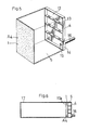
- FIG. 4 An example of using the third preferred embodiment is shown in Fig. 4.
- a panel (A3) is mounted on a ceiling through an edge member (7), that is to say the hollow holes (2 ⁇ ) are made uniform in direction, solid portions being inserted to combine the panels (A3) with each other, a waterproof tape (8) being stuck to a joint portion of the panels (A3) - - - over the moisture-insulating layer (3), and as a result, the panels (A3) - - - being fastened with nails to the edge member (7).
- a sealing material (10) is filled up.
- a back surface of the panel (A3) is prevented from absorbing a moisture by the use of the waterproof tape (8) for the joint portion (side of the moisture-insulating layer) of the panel (A3) between themselves and the sealing materials (10) for the end portions of the wall surface (9) and the panel (A3).
- one end portion of the panel (A3) [an opened end of the hollow hole (2)] is connected to a discharge duct (11) and a vacuum pump is installed in the duct (11) to discharge the moisture within the hollow hole (2 ⁇ ) out of the room.
- the discharge duct (11) is installed on only one side of the preferred embodiment illustrated, it goes without saying that the discharge duct (11) may be installed at both ends.
- a ventilation equipment is used in place of the vacuum pump, the inside of the hollow hole (2 ⁇ ) is decompressed.
- said moisture-absorbing structure (1) is provided with a cover member (4) and said space portion (5) is decompressed.
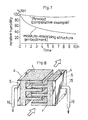
- a concrete example of the fourth preferred embodiment is shown in Figs. 5 to 8.
- the preferred embodiment illustrated in Fig. 2 uses the cover member (4) stuck in the same manner as in the fourth preferred embodiment.
- the cover member (4) used in the present invention includes single metallic materials (such as an aluminium sheet and baking painted steel plate), molded resin materials (such as acrylic resin, PVC resin and ABS resin), glass and the like without having the moisture-absorbing property as well as plywoods and cement plates of which surface layer is coated with a moisture-nonabsorbing layer, such as a polyolefine sheet and vinyl paint, so as to give the moisture- insulating property.
- the moisture-absorbing structure (1) is formed by molding a blend comprising portland cement, bentonite, CaCl2, diethylene glycol and water at a ratio of 350 : 700 : 105 : 105 : 500 by weight and provided with an assembly comprising an opposite surface member (12) made of acrylic resins, a perforated reinforcement (13) and a frame member (14) mounted on one surface thereof as the cover member (4), a pipe (16) led out of a moisture-discharging opening (15) being connected to a vacuum pump at a part of the opposite surface member (12).
- the moisture-absorbing penetrating structure (A4) [comprising the moisture-absorbing structure (1) of 5 mm thick] according to the above described fourth preferred embodiment was mounted on an opened portion (17a) (50 x 40 mm) of a glass case of which inside was adjusted to 100 % in RH and the inside of the glass case was decompressed to an absolute pressure of 50 mmHg by means of the vacuum pump to measure a change of humidity within the glass case (17) closed up tight.
- polyvinyl chloride resin, sodium polyacrylate and plasticizers and the like were blended at a ratio of 36 : 36 : 28 and the resulting blend was foamed by heating using the paste calender method to obtain a sheet of 5 (thickness) x 150 x 150 mm. 5 pieces of the resulting sheet were piled up to form the moisture-absorbing structure (1) (having a mean pore-diameter of 1 micron).
- the pipe (16) was connected to the vacuum pump (absolute pressure: 710 mmHg) and the space portion (5) was subjected to the suction. As a result, water of about 4 g could be collected for 4 hours in the room having a temperature of 17°C and a RH of 50 %.
- Fig. 8 shows another example of the fourth preferred embodiment of the present invention which is a modification of Fig. 4.
- An unevenness is formed on a moisture-absorbing surface and uneven portions of a pair of moisture-absorbing structure (1) with an increased moisture-absorbing surface area are combined.
- the suction is carried out from an opposite surface space portion (5) of the moisture-absorbing structure (1).
- the suction is carried out by means of a vacuum pump driven by an electric motor, but it can be done by any kinds of suction means which is normally used in the field of this art.
Landscapes
- Chemical & Material Sciences (AREA)
- Engineering & Computer Science (AREA)
- Analytical Chemistry (AREA)
- General Chemical & Material Sciences (AREA)
- Oil, Petroleum & Natural Gas (AREA)
- Chemical Kinetics & Catalysis (AREA)
- Combustion & Propulsion (AREA)
- Mechanical Engineering (AREA)
- General Engineering & Computer Science (AREA)
- Drying Of Gases (AREA)
- Solid-Sorbent Or Filter-Aiding Compositions (AREA)
Priority Applications (1)
| Application Number | Priority Date | Filing Date | Title |
|---|---|---|---|
| AT87308280T ATE74790T1 (de) | 1986-09-18 | 1987-09-18 | Produkt und vorrichtung zum entfeuchten. |
Applications Claiming Priority (6)
| Application Number | Priority Date | Filing Date | Title |
|---|---|---|---|
| JP61220375A JPS6377518A (ja) | 1986-09-18 | 1986-09-18 | 除湿用透過体 |
| JP220375/86 | 1986-09-18 | ||
| JP51037/87 | 1987-03-05 | ||
| JP62051037A JPS63218234A (ja) | 1987-03-05 | 1987-03-05 | 吸湿性透過構造体 |
| JP137521/87 | 1987-05-30 | ||
| JP13752187A JPS63300145A (ja) | 1987-05-30 | 1987-05-30 | 除湿用パネル |
Publications (3)
| Publication Number | Publication Date |
|---|---|
| EP0260986A2 true EP0260986A2 (fr) | 1988-03-23 |
| EP0260986A3 EP0260986A3 (en) | 1989-08-16 |
| EP0260986B1 EP0260986B1 (fr) | 1992-04-15 |
Family
ID=27294175
Family Applications (1)
| Application Number | Title | Priority Date | Filing Date |
|---|---|---|---|
| EP87308280A Expired - Lifetime EP0260986B1 (fr) | 1986-09-18 | 1987-09-18 | Produit et dispositif pour enlever l'humidité |
Country Status (3)
| Country | Link |
|---|---|
| US (1) | US4826516A (fr) |
| EP (1) | EP0260986B1 (fr) |
| DE (1) | DE3778263D1 (fr) |
Cited By (6)
| Publication number | Priority date | Publication date | Assignee | Title |
|---|---|---|---|---|
| US4872891A (en) * | 1988-09-06 | 1989-10-10 | The Perkin-Elmer Corporation | Desiccant system |
| EP0335670A3 (fr) * | 1988-03-29 | 1991-10-30 | Daiken Kogyo Kabushiki Kaisha | Dispositif permettant l'observation d'un certain degré d'humidité |
| US5308703A (en) * | 1990-11-28 | 1994-05-03 | Osaka Gas Company Limited | Adsorbent having good heat conductivity |
| US5310593A (en) * | 1990-10-31 | 1994-05-10 | Osaka Gas Company Limited | Adsorbent |
| US5935304A (en) * | 1996-09-19 | 1999-08-10 | United Catalysts Inc. | Desiccant composition |
| AT409094B (de) * | 1999-11-20 | 2002-05-27 | Mann & Hummel Filter | Trockenmittelbox |
Families Citing this family (14)
| Publication number | Priority date | Publication date | Assignee | Title |
|---|---|---|---|---|
| US5092135A (en) * | 1990-11-09 | 1992-03-03 | Charles Cameron | Air conditioning system |
| US5807422A (en) * | 1995-03-03 | 1998-09-15 | Grgich; George R. | Divided radial and spherical desiccant bed adsorption units |
| CA2221138A1 (fr) * | 1995-06-06 | 1996-12-12 | Kimberly-Clark Worldwide, Inc. | Tissu microporeux contenant un adsorbant microbien |
| WO1996039031A1 (fr) * | 1995-06-06 | 1996-12-12 | Kimberly-Clark Worldwide, Inc. | Feuil microporeux contenant un adsorbant microbien |
| US6059859A (en) * | 1997-09-19 | 2000-05-09 | Aeronex, Inc. | Method, composition and apparatus for water removal from non-corrosive gas streams |
| US6264895B1 (en) * | 1999-02-26 | 2001-07-24 | Robert S. Johnson | Evaporator |
| US6559096B1 (en) | 2000-10-18 | 2003-05-06 | Nanopore, Inc. | Desiccant composition |
| DE10155643A1 (de) * | 2001-11-08 | 2003-05-28 | Ipc Process Ct Gmbh | Körper für die Separation einer in einem Gasgemisch enthaltenen Komponente |
| US6858068B2 (en) * | 2002-09-30 | 2005-02-22 | Nanopore, Inc. | Device for providing microclimate control |
| US9458451B2 (en) | 2007-06-21 | 2016-10-04 | Gen-Probe Incorporated | Multi-channel optical measurement instrument |
| DE102014018799A1 (de) * | 2014-12-19 | 2016-06-23 | Bayerisches Zentrum für Angewandte Energieforschung e.V. | Feuchtespeicherndes Stoffgemisch und Bauplatte daraus |
| US10184674B2 (en) | 2015-09-16 | 2019-01-22 | Kabushiki Kaisha Toshiba | Vapor separator and dehumidifier using the same |
| JP2017159268A (ja) * | 2016-03-11 | 2017-09-14 | 株式会社東芝 | 水蒸気分離体とそれを用いた除湿装置 |
| CN113148437B (zh) * | 2021-04-08 | 2022-08-23 | 南安市恒发纸品包装有限公司 | 一种柔性支撑的防潮纸箱 |
Family Cites Families (8)
| Publication number | Priority date | Publication date | Assignee | Title |
|---|---|---|---|---|
| US2225990A (en) * | 1937-12-22 | 1940-12-24 | Guy J Henry | Dehydrator |
| US3225524A (en) * | 1961-05-15 | 1965-12-28 | James H Berrian | Apparatus for separating liquid from a binary phase liquid-gas mixture |
| US3170872A (en) * | 1962-08-03 | 1965-02-23 | Parker Hannifin Corp | Ceramic block filter drier |
| US3505794A (en) * | 1968-05-29 | 1970-04-14 | Air Inc Van | Air filter |
| US4377398A (en) * | 1977-04-21 | 1983-03-22 | Motorola Inc. | Heat energized vapor adsorbent pump |
| JPS5628639A (en) * | 1979-08-18 | 1981-03-20 | Tokuyama Soda Co Ltd | Desiccant |
| JPS6062598A (ja) * | 1983-09-02 | 1985-04-10 | Toho Gas Kk | 熱交換素子の製造法 |
| US4645519A (en) * | 1984-06-06 | 1987-02-24 | The United States Of America As Represented By The United States Department Of Energy | Composite desiccant structure |
-
1987
- 1987-09-17 US US07/097,885 patent/US4826516A/en not_active Expired - Fee Related
- 1987-09-18 DE DE8787308280T patent/DE3778263D1/de not_active Expired - Lifetime
- 1987-09-18 EP EP87308280A patent/EP0260986B1/fr not_active Expired - Lifetime
Cited By (7)
| Publication number | Priority date | Publication date | Assignee | Title |
|---|---|---|---|---|
| EP0335670A3 (fr) * | 1988-03-29 | 1991-10-30 | Daiken Kogyo Kabushiki Kaisha | Dispositif permettant l'observation d'un certain degré d'humidité |
| US4872891A (en) * | 1988-09-06 | 1989-10-10 | The Perkin-Elmer Corporation | Desiccant system |
| US5310593A (en) * | 1990-10-31 | 1994-05-10 | Osaka Gas Company Limited | Adsorbent |
| US5308703A (en) * | 1990-11-28 | 1994-05-03 | Osaka Gas Company Limited | Adsorbent having good heat conductivity |
| US5935304A (en) * | 1996-09-19 | 1999-08-10 | United Catalysts Inc. | Desiccant composition |
| US6217701B1 (en) | 1996-09-19 | 2001-04-17 | United Catalysts Inc. | Desiccant composition |
| AT409094B (de) * | 1999-11-20 | 2002-05-27 | Mann & Hummel Filter | Trockenmittelbox |
Also Published As
| Publication number | Publication date |
|---|---|
| US4826516A (en) | 1989-05-02 |
| DE3778263D1 (de) | 1992-05-21 |
| EP0260986B1 (fr) | 1992-04-15 |
| EP0260986A3 (en) | 1989-08-16 |
Similar Documents
| Publication | Publication Date | Title |
|---|---|---|
| EP0260986B1 (fr) | Produit et dispositif pour enlever l'humidité | |
| US6178966B1 (en) | Heat and moisture exchange apparatus for architectural applications | |
| EP0762382A1 (fr) | Panneau permettant de realiser une paroi d'insonorisation | |
| US5484970A (en) | Acoustic insulator | |
| JP5048454B2 (ja) | 吸脱着エレメント、およびそれを用いた二酸化炭素濃度調整装置、二酸化炭素濃度調整システム、並びに二酸化炭素濃度調整方法。 | |
| JPH05309771A (ja) | 臭気移行の極めて少ない全熱交換器用素子 | |
| JPH08168633A (ja) | 無パツキン・無フレーム形臭気発生物質および/または有害物質フイルタの使用 | |
| AU2004219911A1 (en) | Spacer section for glass insulation panes | |
| US20120012290A1 (en) | Architectural heat and moisture exchange | |
| WO2013012639A1 (fr) | Échangeur architectural de chaleur et d'humidité | |
| EP0335670B1 (fr) | Dispositif permettant l'observation d'un certain degré d'humidité | |
| JPH0688632A (ja) | 輻射冷房用パネル及び輻射冷房構造 | |
| US4818602A (en) | Hygroscopic composite material | |
| JPS63218234A (ja) | 吸湿性透過構造体 | |
| JPH11216335A (ja) | 脱臭装置 | |
| JPH1134204A (ja) | 環境浄化機能付き表装用シート及び建材ボード | |
| JP3022999B2 (ja) | 地下室の内装構造 | |
| EP0686732A1 (fr) | Panneau isolant thermique | |
| JPH06101987A (ja) | 空調用エレメント | |
| JPH07103614B2 (ja) | 除湿内装構造 | |
| JPS63300145A (ja) | 除湿用パネル | |
| JPS6370740A (ja) | 吸湿性複合材 | |
| JPH01297125A (ja) | 除湿装置 | |
| JPH10317578A (ja) | 吸放湿性板材 | |
| JPH0116507Y2 (fr) |
Legal Events
| Date | Code | Title | Description |
|---|---|---|---|
| PUAI | Public reference made under article 153(3) epc to a published international application that has entered the european phase |
Free format text: ORIGINAL CODE: 0009012 |
|
| 17P | Request for examination filed |
Effective date: 19870924 |
|
| AK | Designated contracting states |
Kind code of ref document: A2 Designated state(s): AT BE CH DE ES FR GB GR IT LI LU NL SE |
|
| RBV | Designated contracting states (corrected) |
Designated state(s): AT BE CH DE FR GB IT LI NL SE |
|
| PUAL | Search report despatched |
Free format text: ORIGINAL CODE: 0009013 |
|
| AK | Designated contracting states |
Kind code of ref document: A3 Designated state(s): AT BE CH DE FR GB IT LI NL SE |
|
| 17Q | First examination report despatched |
Effective date: 19901116 |
|
| ITF | It: translation for a ep patent filed | ||
| GRAA | (expected) grant |
Free format text: ORIGINAL CODE: 0009210 |
|
| AK | Designated contracting states |
Kind code of ref document: B1 Designated state(s): AT BE CH DE FR GB IT LI NL SE |
|
| PG25 | Lapsed in a contracting state [announced via postgrant information from national office to epo] |
Ref country code: SE Effective date: 19920415 Ref country code: NL Effective date: 19920415 Ref country code: LI Effective date: 19920415 Ref country code: CH Effective date: 19920415 Ref country code: BE Effective date: 19920415 Ref country code: AT Effective date: 19920415 |
|
| REF | Corresponds to: |
Ref document number: 74790 Country of ref document: AT Date of ref document: 19920515 Kind code of ref document: T |
|
| REF | Corresponds to: |
Ref document number: 3778263 Country of ref document: DE Date of ref document: 19920521 |
|
| ET | Fr: translation filed | ||
| REG | Reference to a national code |
Ref country code: CH Ref legal event code: PL |
|
| PGFP | Annual fee paid to national office [announced via postgrant information from national office to epo] |
Ref country code: GB Payment date: 19920907 Year of fee payment: 6 |
|
| PGFP | Annual fee paid to national office [announced via postgrant information from national office to epo] |
Ref country code: FR Payment date: 19920909 Year of fee payment: 6 |
|
| NLV1 | Nl: lapsed or annulled due to failure to fulfill the requirements of art. 29p and 29m of the patents act | ||
| PGFP | Annual fee paid to national office [announced via postgrant information from national office to epo] |
Ref country code: DE Payment date: 19921005 Year of fee payment: 6 |
|
| PLBE | No opposition filed within time limit |
Free format text: ORIGINAL CODE: 0009261 |
|
| STAA | Information on the status of an ep patent application or granted ep patent |
Free format text: STATUS: NO OPPOSITION FILED WITHIN TIME LIMIT |
|
| 26N | No opposition filed | ||
| PG25 | Lapsed in a contracting state [announced via postgrant information from national office to epo] |
Ref country code: GB Effective date: 19930918 |
|
| GBPC | Gb: european patent ceased through non-payment of renewal fee |
Effective date: 19930918 |
|
| PG25 | Lapsed in a contracting state [announced via postgrant information from national office to epo] |
Ref country code: FR Free format text: LAPSE BECAUSE OF NON-PAYMENT OF DUE FEES Effective date: 19940531 |
|
| PG25 | Lapsed in a contracting state [announced via postgrant information from national office to epo] |
Ref country code: DE Effective date: 19940601 |
|
| REG | Reference to a national code |
Ref country code: FR Ref legal event code: ST |
|
| PG25 | Lapsed in a contracting state [announced via postgrant information from national office to epo] |
Ref country code: IT Free format text: LAPSE BECAUSE OF NON-PAYMENT OF DUE FEES;WARNING: LAPSES OF ITALIAN PATENTS WITH EFFECTIVE DATE BEFORE 2007 MAY HAVE OCCURRED AT ANY TIME BEFORE 2007. THE CORRECT EFFECTIVE DATE MAY BE DIFFERENT FROM THE ONE RECORDED. Effective date: 20050918 |