EP0261003B1 - Einrichtung zur schrittweisen Fernortung von Zwischenverstärkerpaaren in einer digitalen Leitung - Google Patents
Einrichtung zur schrittweisen Fernortung von Zwischenverstärkerpaaren in einer digitalen Leitung Download PDFInfo
- Publication number
- EP0261003B1 EP0261003B1 EP87401717A EP87401717A EP0261003B1 EP 0261003 B1 EP0261003 B1 EP 0261003B1 EP 87401717 A EP87401717 A EP 87401717A EP 87401717 A EP87401717 A EP 87401717A EP 0261003 B1 EP0261003 B1 EP 0261003B1
- Authority
- EP
- European Patent Office
- Prior art keywords
- repeaters
- width
- signal
- sequence
- interruption
- Prior art date
- Legal status (The legal status is an assumption and is not a legal conclusion. Google has not performed a legal analysis and makes no representation as to the accuracy of the status listed.)
- Expired - Lifetime
Links
- 230000000630 rising effect Effects 0.000 claims description 15
- 230000005540 biological transmission Effects 0.000 claims description 7
- 230000002457 bidirectional effect Effects 0.000 claims description 2
- 238000009434 installation Methods 0.000 description 11
- 230000008929 regeneration Effects 0.000 description 6
- 238000011069 regeneration method Methods 0.000 description 6
- 230000001960 triggered effect Effects 0.000 description 5
- 238000012544 monitoring process Methods 0.000 description 4
- 230000006978 adaptation Effects 0.000 description 3
- 230000003321 amplification Effects 0.000 description 2
- 230000000903 blocking effect Effects 0.000 description 2
- 238000010586 diagram Methods 0.000 description 2
- 238000003199 nucleic acid amplification method Methods 0.000 description 2
- 238000011084 recovery Methods 0.000 description 2
- 230000033764 rhythmic process Effects 0.000 description 2
- 102100026887 Beta-defensin 103 Human genes 0.000 description 1
- 101000912247 Homo sapiens Beta-defensin 103 Proteins 0.000 description 1
- 238000004458 analytical method Methods 0.000 description 1
- 238000006243 chemical reaction Methods 0.000 description 1
- 238000001514 detection method Methods 0.000 description 1
- 230000018109 developmental process Effects 0.000 description 1
- 238000010304 firing Methods 0.000 description 1
- 238000004519 manufacturing process Methods 0.000 description 1
- 239000013307 optical fiber Substances 0.000 description 1
- 230000000737 periodic effect Effects 0.000 description 1
Images

Classifications
-
- H—ELECTRICITY
- H04—ELECTRIC COMMUNICATION TECHNIQUE
- H04B—TRANSMISSION
- H04B17/00—Monitoring; Testing
- H04B17/40—Monitoring; Testing of relay systems
- H04B17/407—Monitoring; Testing of relay systems without selective localization
- H04B17/408—Monitoring; Testing of relay systems without selective localization using successive loop-backs
Definitions
- the present invention relates to improvements to a step-by-step remote location installation for pairs of repeaters in a digital link.
- the invention relates to a step-by-step remote location installation of pairs of first and second repeaters in a digital link between first and second terminal equipment.
- Said link is composed of a first channel in which the first repeaters are interconnected through respective first switching means which are closed to transmit a first digital signal from the first equipment to the second equipment, and a second channel in which the interconnects are second repeaters through respective second switching means which are closed to transmit a second digital signal from the second device to the first device.
- the first equipment comprises means, including generators of remote location signals and a remote location control unit, for cutting the first digital signal by sequences of interruptions.
- Each of the sequences includes k first interrupts having a predetermined width and a last interrupt respectively preceded by k first signal fields having a predetermined width and a last field, k being an integer.
- r sequences are transmitted successively in the first channel to telelocate a pair of repeaters having an integer range r counted from the first device, the last field of the last sequence of r sequences having a width greater than that of the other signal fields.
- Each pair of first and second repeaters is associated with means including a timing circuit and a counter-decoder for counting the interruptions of each sequence, and with means including a monostable flip-flop which can be reset to reset said means for counting in response to an interruption in the first signal having a first width exceeding the sum of the widths of a first field and a first interruption in a sequence.
- the means for counting controls an opening of the respective first switching means to disconnect said first repeater from the first next row repeater, and an opening of the respective second switching means to disconnect said second repeater from the second next row repeater and to connect said first and second repeaters through a respective feedback loop as soon as the means for counting have a count equal to k.
- the means for counting also controls closings of the respective first and second switching means when the count is different from k.
- the repeater includes a self-adjusting equalizer including a variable gain amplifier, called a channel section corrector, and an automatic gain control circuit (AGC) in order to compensate for the attenuation of the digital signal received transmitted through the respective road section.
- AGC automatic gain control circuit
- the disconnection with respect to the first terminal equipment of the first repeaters by opening the respective first switching means or by opening the first switching means of a telelocated pair can in practice cause untimely looping of the pairs of repeaters disconnected due to a noise signal, and / or cause a regeneration fault in the transmitted telelocation sequence after unwinding of a previous pair, due to the maximum gain of the gain control circuit which does not allow suitable regeneration ble and therefore a correct copy of a telelocation sequence.
- the present invention aims to remedy mainly the drawbacks mentioned above, by ensuring that any interruption of the first digital signal transmitted in the first repeaters, including those having a rank higher than that of a pair of repeaters to be telelocated, is less than a width such that it does not cause any adaptation with maximum gain.
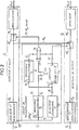
- the remote location installation shown in Fig.1 relates to a bidirectional digital link transmitting digital signals at 2048 kbit / s between a first terminal equipment called supervisor 1 and a second terminal equipment called supervised 2.
- the link is of the four-wire type, that is to say comprises a first channel called to go of the coaxial line type for transmitting a first digital signal MIC from the equipment 1 to the equipment 2, and a second so-called coaxial line type return channel for transmitting a second digital MIC signal from equipment 2 to equipment 1.
- the link is divided into R + 1 pairs of line sections 3 1 -4 1 to 3 R + 1 - 4 R + 1 delimited by R pairs of repeaters 5 1 -6 1 to 5 R -6 R marking the link.
- Line sections 3 1 to 3 R + 1 and repeaters 5 1 to 5 R are assigned to the outgoing channel, and sections 4 R + 1 to 4 1 and repeaters 6 R to 6 1 are assigned to the way back.
- Line sections 3 1 and 4 1 and line sections 3 R + 1 and 4 R + 1 are connected respectively to the monitoring equipment 1 and to the remote monitored equipment 2.
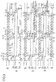
- each of the go repeaters such as the 5 r repeater, where r is an integer between 1 and R, successively comprises from the previous section 3 r of the go path, an input circuit 51 an interrupt circuit 52 r represented diagrammatically by a switch, and an output circuit 53 r connected to the following section 5 r + 1 of the go path.
- the input circuit 51 includes at the input an adaptation transformer, then a self-adjusting equalizer with an automatic gain control circuit (AGC), and a regeneration and rhythm recovery circuit.
- AGC automatic gain control circuit
- the output circuit 53 r includes an amplification circuit and an output transformer.
- each of the return repeaters such as the repeater 6 r , successively comprises from the previous section 4 r + 1 , an input circuit 61 r , a switching circuit 62 r represented diagrammatically by a switch with two stationary input contacts and a movable output contact, and an output circuit 63 connected to the adjoining section 4 of the return path.
- the input circuit 61 r comprises an adaptation transformer followed by a self-adaptive equalizer with an automatic gain control circuit.
- the output circuit 63 r comprises, from the output contact of the switch 62 r , a regeneration and rhythm recovery circuit, an amplification circuit and an output transformer.
- Each of the pairs of repeaters is associated with a respective remote positioning circuit 7 r intended mainly to control the switch 52 and the switch 62 r and to complete the link from the equipment. terminal monitoring 1 through a loopback path 56 between repeaters 5 and 6 r .
- the telelocation circuit essentially comprises an envelope detector 70, a counter 71, two monostable flip-flops 72 and 73 and other logic components 74 to 78.
- An input of the envelope detector 70 and a clock input H 3 of the flip-flop 73 are connected to an output 51 r of the input circuit 51 r .
- the output 51 r + is in fact that of the corresponding regeneration circuit transmitting one of two regenerated binary signals obtained from the digital signal MIC transmitted by section 3 of the outgoing channel. It is assumed here that the digital signal is coded with a high-density bipolar line code HDBn, and that the binary signal delivered by the output 51 r + corresponds to an HDBn + signal which is in state "1" only in correspondence with positive bipolar marks in the coded signal.
- HDBn code can only contain n consecutive zeros, and consequently the HDBn signal can only contain (2n + 1) consecutive zeros, corresponding to a duration of 3.4 us for the HDB3 code to which we will refer in the following.
- the envelope detector 70 is mainly intended to inhibit any cut, or interruption, normally found in the digital signal MIC of the outgoing channel, so as not to be counted by the counter 71 and not to trigger the flip-flop 72.
- the response time ⁇ of the detector 70 is chosen clearly. greater than the duration of 3.4 ⁇ s, but smaller than micro-cuts of a telelocation sequence defined below. Typically, r is between 30 ⁇ s and 250 us.
- the detector 70 delivers a detected binary signal corresponding to the digital signal transmitted in the line and having no micro-cuts less than T , or more precisely having micro-cuts corresponding to those included in the first digital signal transmitted but with a reduced width of T from the falling edges of these micro-cuts.
- Clock inputs H 1 and H 2 of the counter 71 and of the flip-flop 72 are connected to the output of the detector 70 through an inverter 74.
- the Hi input is triggered by rising edges of the detected signal corresponding to falling edges of the first digital signal transmitted.
- the flip-flop 72 is a monostable flip-flop which is retriggerable by falling edges of the signal leaving the inverter 74 and corresponding to rising edges of the first digital signal transmitted, that is to say front edges of fields of this first signal digital.
- Reverse output Q z of flip-flop 72 is at state "0" in response to a falling edge at input H 2 , this state "0" remaining until the end of a time constant ⁇ 2 during which no falling edge is not present at the entrance H 2 .
- the output Cs of the counter 71 and the output 0 2 of the flip-flop 72 are connected through an inverter 75 and directly to first inputs and second inputs of an OR gate 76 and an AND gate 77 respectively.
- An output from the OR gate 76 controls the switch 52 r, while an output from the inverter 75 controls the switch 62 r . In normal operation of the link, as shown in FIG.
- the second monostable flip-flop 73 has a clock input H 3 retriggerable by falling edges of the signal HBD3 + delivered by the terminal 51 r + .
- the flip-flop 73 has a time constant T 3 less than T 2 .
- An inverse output C 3 of the flip-flop 73 thus passes to the state "0" in response to a falling edge in the digital signal of the forward channel, including for falling edges preceding sequences of "0" in the digital signals.
- the exit Q s and an output of the AND gate 77 are respectively connected to two inputs of an OR gate 78 having an output connected to a reset input RESET of the counter 71.
- the counter 71 is reset to zero in response to a state " 1 at the exit of door 78.
- the terminal equipment 1 and 2 comprise circuits necessary for the remote location of the repeaters, for the remote supply of the repeaters in the case where the connection is made by cables, to the development of specific digital test signals, such as pseudo-random signals, in order to detect faults in the forward and return paths of the link, to the production of an indication signal d alarm (SIA) which is transmitted outside the link in response to fault detection, and the transmission of an alarm inhibit signal which is transmitted in the link in response to a signal alarm indication from outside the link.
- SIA indication signal d alarm
- the terminal monitoring equipment 1 comprises a control unit 11, preferably removable including a microprocessor, an alphanumeric keyboard and a display device to allow an operator to order automatically or manually, a step-by-step remote positioning. step of a pair of repeaters of rank given 1 to R, and to select a test signal and programs for the analysis of specific circuits of remote repeater.
- the equipment 1 contains in particular a test signal generator 12, a remote sequence sequence generator 13, a signal mixer 14 and a trunk 15.
- a remote positioning signal comprises SE remote positioning sequences each intended to loop, possibly to test, then to terminate key a respective pair of repeaters.
- Each of the fields Si to S 8 and the field S 9 when the latter precedes another sequence, has a predetermined width TS and precedes an interruption or micro-break without test signal I 1 to 1 9 having a predetermined width TI, in practice equal to TS.
- the cutting signal established by the generator 13 is therefore a pulse signal which cuts out in the mixer 14 the test signal produced by the generator 12 into the remote positioning signal leaving the mixer 14.
- the remote positioning signal is transmitted in the first section 3 1 of the path to go through the trunk 15, and is partially recovered by the control unit 11 from section 4 1 of the return path when a pair of repeaters is looped.
- the trunk 15 may comprise, in addition to switches for introducing and recovering the test signal, a pair of repeaters.
- the pair of repeaters included in the trunk plays the role of the first pair 5 1 -6 1 .
- the last pair of repeaters 5 R -6 R can be included in a trunk of the remote terminal equipment 2.
- a remote location of a pair of repeaters is as follows.
- the signal telelocation Before the transmission of two telelocation sequences SE 1 and SE 2 intended respectively to loop and loosen the first fleeting pair of repeaters 5 1 -6 1 and to loop and test the second pair of repeaters 5 2 -6 2 to be telelocated, the signal telelocation includes a wide interruption l o having a width To greater than ⁇ 3 and preceding the first field S 1 in the first sequence SE 1 .
- every second flip-flops 73 in circuits 7 1 to 7 R are triggered and the outputs Q 3 of these flip-flops change to "1" after a duration T 3 , less than To, until the first falling edge appearing in the field Si of the sequence SE 1 .
- the looping and unwinding of the repeaters 5 1 and 6 1 causes a width interruption (TS + 2 TI) which is greater than the time constant ⁇ 3 of the flip-flops 73.
- repeaters 5 2 -6 2 to 5 R -6 R and allows the transmission of the following telelocation sequence SE 2 to repeaters 5 2 to 5 R.
- T 2 is earlier than TI + TS
- r 2 is greater than TS + ⁇ 1 or preferably greater than 2 TS + 2 TI, so that the flip-flops 73 are not triggered during the looping-unwinding operation of the pair of repeaters 5 1 -6 1 .
- the telelocation sequence of the same rank such as the sequence SE 2
- the sequence SE 2 has a last signal field S 9 having a width exceeding the time constant T 2 ; during this field S 9 , the test signal is truly analyzed in the equipment 1 with a view to locating faults in the pair of remote-located repeaters.
- a remote positioning circuit 7 r according to the invention is freed against any looping command of the pair of repeaters associated 5 r -6 by undesirable interruptions due to lightning for example.
- connection between the terminal equipment can be partly or totally with coaxial cables, optical fibers or microwave links.
- the signals transmitted in the link can be of the analog type with analog-digital and digital-analog conversions in repeaters.
- a switch 62 can be replaced by two switches, one in the return path, the other in the loopback path 56 between the go and return paths.
- the switch 52 r and the switch 62 r can be interconnected at other locations than those shown in FIG. 2, for example respectively at the output of the output circuit 53 and at the input of the output circuit.
- Switches and switches can be of the relay contact or transistor type.
- the inputs of the detector 70 and of the flip-flop 73 can receive the signal HDBn- instead of the signal HDBn + , or receive the signals HDBn and HDBn- respectively, or receive the digital signal regenerated through a binary-bipolar converter.
Landscapes
- Physics & Mathematics (AREA)
- Electromagnetism (AREA)
- Engineering & Computer Science (AREA)
- Computer Networks & Wireless Communication (AREA)
- Signal Processing (AREA)
- Monitoring And Testing Of Transmission In General (AREA)
- Dc Digital Transmission (AREA)
- Maintenance And Management Of Digital Transmission (AREA)
Claims (5)
Applications Claiming Priority (2)
| Application Number | Priority Date | Filing Date | Title |
|---|---|---|---|
| FR8610758A FR2602108B1 (fr) | 1986-07-24 | 1986-07-24 | Perfectionnements a une installation de telelocalisation pas-a-pas de paires de repeteurs dans une liaison numerique |
| FR8610758 | 1986-07-24 |
Publications (2)
| Publication Number | Publication Date |
|---|---|
| EP0261003A1 EP0261003A1 (de) | 1988-03-23 |
| EP0261003B1 true EP0261003B1 (de) | 1991-05-02 |
Family
ID=9337708
Family Applications (1)
| Application Number | Title | Priority Date | Filing Date |
|---|---|---|---|
| EP87401717A Expired - Lifetime EP0261003B1 (de) | 1986-07-24 | 1987-07-23 | Einrichtung zur schrittweisen Fernortung von Zwischenverstärkerpaaren in einer digitalen Leitung |
Country Status (4)
| Country | Link |
|---|---|
| US (1) | US4815101A (de) |
| EP (1) | EP0261003B1 (de) |
| DE (1) | DE3769736D1 (de) |
| FR (1) | FR2602108B1 (de) |
Families Citing this family (2)
| Publication number | Priority date | Publication date | Assignee | Title |
|---|---|---|---|---|
| FR2628273B1 (fr) * | 1988-03-02 | 1994-08-12 | Saleeby Robert | Transmetteur de trains d'impulsions |
| DE10058775C2 (de) * | 2000-11-27 | 2003-03-06 | Adva Ag | Sende-/Empfangseinrichtung, insbesondere Repeater-Verstärker oder Signal-Converter |
Family Cites Families (6)
| Publication number | Priority date | Publication date | Assignee | Title |
|---|---|---|---|---|
| US3649777A (en) * | 1968-04-26 | 1972-03-14 | Nippon Electric Co | Supervisory apparatus for pcm regenerative repeaters |
| US4161635A (en) * | 1978-07-31 | 1979-07-17 | Bell Telephone Laboratories, Incorporated | Address verification system |
| DE2904057A1 (de) * | 1979-02-02 | 1980-08-07 | Siemens Ag | Adressenfreie fehlerortung mittels schleifenschluss fuer nachrichtenuebertragungsstrecken |
| FR2467511A1 (fr) * | 1979-10-08 | 1981-04-17 | Legras Jacques | Systeme de telecontrole pour liaisons de telecommunications telealimentees |
| FR2486335B1 (fr) * | 1980-07-02 | 1988-03-11 | Telecommunications Sa | Installation de telelocalisation pas-a-pas de circuits d'amplification intermediaires d'une liaison mic |
| JPS5842328A (ja) * | 1981-09-07 | 1983-03-11 | Hitachi Ltd | 遠隔折返し制御方式 |
-
1986
- 1986-07-24 FR FR8610758A patent/FR2602108B1/fr not_active Expired
-
1987
- 1987-07-23 US US07/076,816 patent/US4815101A/en not_active Expired - Fee Related
- 1987-07-23 DE DE8787401717T patent/DE3769736D1/de not_active Expired - Fee Related
- 1987-07-23 EP EP87401717A patent/EP0261003B1/de not_active Expired - Lifetime
Also Published As
| Publication number | Publication date |
|---|---|
| FR2602108A1 (fr) | 1988-01-29 |
| FR2602108B1 (fr) | 1988-11-10 |
| US4815101A (en) | 1989-03-21 |
| DE3769736D1 (de) | 1991-06-06 |
| EP0261003A1 (de) | 1988-03-23 |
Similar Documents
| Publication | Publication Date | Title |
|---|---|---|
| EP0043308B1 (de) | Einrichtung zur schrittweisen Fernortung von Zwischenverstärkern einer PCM-Verbindung | |
| EP0032327B1 (de) | Verfahren und Anlage zur Sicherung eines digitalen Übertragungskabels | |
| CA1075361A (fr) | Transmission de donnees notamment avec modulation delta | |
| DE69129992T2 (de) | Passives optisches netzwerk | |
| US4623884A (en) | Transmission line control system with by-pass control | |
| EP0192061A1 (de) | Einrichtung zur automatischen Verstärkungsregelung eines T.D.M.A.-Empfängers | |
| FR2477738A1 (fr) | Appareil de commande et de controle destine a etre utilise entre un poste central de calculateur et des postes terminaux | |
| EP0289237A2 (de) | Manchester-Code-Empfänger | |
| CH669057A5 (fr) | Installation de surveillance et d'alarme. | |
| EP0454036B1 (de) | Verfahren und Anordnung für die Rückkehr zu einer normalen Verbindung nach Benutzung einer Hilfsverbindung in einem Datenübertragungssystem | |
| EP0261003B1 (de) | Einrichtung zur schrittweisen Fernortung von Zwischenverstärkerpaaren in einer digitalen Leitung | |
| EP0090728B1 (de) | Verfahren zur gemeinsamen Übertragung eines Signals im HDBN-Kode und eines binären Hilfssignals, Kodierer und Dekodierer nach diesem Verfahren und System zur Fernüberwachung von Zwischenverstärkern einer Digitalverbindung mit Hilfe solcher Hilfssignale | |
| EP0161177A1 (de) | Verfahren und Einrichtung zur Wiedergewinnung des Rahmenverriegelungswortes mit verteilten Bits in einem digitalen Signal | |
| FR2462715A1 (fr) | Systeme de localisation de defaut pour circuit de transmission bidirectionnelle simultanee a repeteurs | |
| EP0014110B1 (de) | Sender-Empfänger und dessen Verwendung in einem Nachrichtenübertragungsnetz | |
| EP1766868B1 (de) | System und verfahren zur erkennung von eingang in einem signalübertragungssystem | |
| FR2570563A1 (fr) | Un reseau local pour transmission de donnees numeriques sur cable telephonique et dispositif permettant la realisation de ce reseau | |
| JP3457280B2 (ja) | バイポーラデータストリームにおける妨害を抑圧するための方法及びこの方法を実施するための回路装置 | |
| US5629789A (en) | Passive optical repeater bypass for optical fiber systems | |
| EP0367688B1 (de) | Verfahren und Anordnung zur Ermittlung einer Unterbrechung in einer Übertragungsverbindung | |
| US4658395A (en) | Method for locating faults in a carrier subscriber communication system | |
| EP0395483B1 (de) | Doppelringkommunikationssystem | |
| US4642426A (en) | Apparatus for locating faults in a carrier subscriber communication system | |
| EP1021016B1 (de) | Gerät zur Unterscheidung von Fehlern auf einer digitalen Mietleitung | |
| SU1598184A2 (ru) | Устройство контрол цифровых световодных систем передачи информации |
Legal Events
| Date | Code | Title | Description |
|---|---|---|---|
| PUAI | Public reference made under article 153(3) epc to a published international application that has entered the european phase |
Free format text: ORIGINAL CODE: 0009012 |
|
| AK | Designated contracting states |
Kind code of ref document: A1 Designated state(s): DE GB IT |
|
| 17P | Request for examination filed |
Effective date: 19880905 |
|
| 17Q | First examination report despatched |
Effective date: 19900917 |
|
| GRAA | (expected) grant |
Free format text: ORIGINAL CODE: 0009210 |
|
| AK | Designated contracting states |
Kind code of ref document: B1 Designated state(s): DE GB IT |
|
| REF | Corresponds to: |
Ref document number: 3769736 Country of ref document: DE Date of ref document: 19910606 |
|
| GBT | Gb: translation of ep patent filed (gb section 77(6)(a)/1977) | ||
| ITF | It: translation for a ep patent filed | ||
| PLBE | No opposition filed within time limit |
Free format text: ORIGINAL CODE: 0009261 |
|
| STAA | Information on the status of an ep patent application or granted ep patent |
Free format text: STATUS: NO OPPOSITION FILED WITHIN TIME LIMIT |
|
| 26N | No opposition filed | ||
| PGFP | Annual fee paid to national office [announced via postgrant information from national office to epo] |
Ref country code: GB Payment date: 19950619 Year of fee payment: 9 |
|
| PGFP | Annual fee paid to national office [announced via postgrant information from national office to epo] |
Ref country code: DE Payment date: 19950706 Year of fee payment: 9 |
|
| PG25 | Lapsed in a contracting state [announced via postgrant information from national office to epo] |
Ref country code: GB Effective date: 19960723 |
|
| GBPC | Gb: european patent ceased through non-payment of renewal fee |
Effective date: 19960723 |
|
| PG25 | Lapsed in a contracting state [announced via postgrant information from national office to epo] |
Ref country code: DE Effective date: 19970402 |
|
| PG25 | Lapsed in a contracting state [announced via postgrant information from national office to epo] |
Ref country code: IT Free format text: LAPSE BECAUSE OF NON-PAYMENT OF DUE FEES;WARNING: LAPSES OF ITALIAN PATENTS WITH EFFECTIVE DATE BEFORE 2007 MAY HAVE OCCURRED AT ANY TIME BEFORE 2007. THE CORRECT EFFECTIVE DATE MAY BE DIFFERENT FROM THE ONE RECORDED. Effective date: 20050723 |