EP0454036B1 - Verfahren und Anordnung für die Rückkehr zu einer normalen Verbindung nach Benutzung einer Hilfsverbindung in einem Datenübertragungssystem - Google Patents
Verfahren und Anordnung für die Rückkehr zu einer normalen Verbindung nach Benutzung einer Hilfsverbindung in einem Datenübertragungssystem Download PDFInfo
- Publication number
- EP0454036B1 EP0454036B1 EP91106457A EP91106457A EP0454036B1 EP 0454036 B1 EP0454036 B1 EP 0454036B1 EP 91106457 A EP91106457 A EP 91106457A EP 91106457 A EP91106457 A EP 91106457A EP 0454036 B1 EP0454036 B1 EP 0454036B1
- Authority
- EP
- European Patent Office
- Prior art keywords
- link
- terminal equipment
- transmission
- modem
- normal
- Prior art date
- Legal status (The legal status is an assumption and is not a legal conclusion. Google has not performed a legal analysis and makes no representation as to the accuracy of the status listed.)
- Expired - Lifetime
Links
- 230000005540 biological transmission Effects 0.000 title claims abstract description 96
- 238000000034 method Methods 0.000 title claims abstract description 71
- 238000001514 detection method Methods 0.000 claims abstract description 33
- 238000012795 verification Methods 0.000 claims abstract description 20
- 230000004044 response Effects 0.000 claims description 27
- 238000012545 processing Methods 0.000 claims description 16
- 238000004891 communication Methods 0.000 claims description 13
- 230000000977 initiatory effect Effects 0.000 claims description 13
- 230000006866 deterioration Effects 0.000 claims description 5
- 230000008859 change Effects 0.000 claims description 3
- 230000015556 catabolic process Effects 0.000 description 9
- 238000006731 degradation reaction Methods 0.000 description 9
- 230000007704 transition Effects 0.000 description 9
- 230000007257 malfunction Effects 0.000 description 7
- 238000010586 diagram Methods 0.000 description 6
- 230000008569 process Effects 0.000 description 5
- 238000004804 winding Methods 0.000 description 4
- 238000006677 Appel reaction Methods 0.000 description 3
- 239000003999 initiator Substances 0.000 description 2
- 238000012423 maintenance Methods 0.000 description 2
- 230000008054 signal transmission Effects 0.000 description 2
- 238000012360 testing method Methods 0.000 description 2
- 238000007796 conventional method Methods 0.000 description 1
- 230000008034 disappearance Effects 0.000 description 1
- 230000006870 function Effects 0.000 description 1
- 238000004519 manufacturing process Methods 0.000 description 1
- 238000000926 separation method Methods 0.000 description 1
- 230000011664 signaling Effects 0.000 description 1
- 230000007480 spreading Effects 0.000 description 1
Images


Classifications
-
- H—ELECTRICITY
- H04—ELECTRIC COMMUNICATION TECHNIQUE
- H04L—TRANSMISSION OF DIGITAL INFORMATION, e.g. TELEGRAPHIC COMMUNICATION
- H04L1/00—Arrangements for detecting or preventing errors in the information received
- H04L1/22—Arrangements for detecting or preventing errors in the information received using redundant apparatus to increase reliability
Definitions
- the present invention relates to data transmission.
- It relates more particularly to data transmission systems comprising, for the transmission of data between two end devices, a so-called normal link on which data transmission takes place in normal times, and a so-called backup link, used in normal link malfunction.
- the normal link is most often constituted by a so-called specialized link, and the backup link by a link using the switched telephone network.
- the normal link is most often constituted by a so-called specialized link, and the backup link by a link using the switched telephone network.
- one or the other of these terms will be used interchangeably.
- the object of the present invention is to return to the normal link after using the emergency link.
- Certain methods are known for carrying out such a return, consisting for example of regularly carrying out transmission attempts on the normal link with transmission stopping on the backup link at the corresponding times, or even of maintaining the transmission on the backup link, while by simultaneously checking the continuity of the normal link by means of a specific signaling frequency transmitted on it.
- the present invention relates to a method making it possible to avoid these drawbacks.
- the subject of the present invention is a method of returning to a normal link after using a backup link in a data transmission system comprising two such links between two end devices, the second of these links being used in the event of malfunction of the first, this method comprising, parallel to the transmission on the emergency link, a prior check of the continuity of the normal link, and being essentially characterized in that this prior check comprises a simultaneous transmission of a signal data by one of the end devices, said end device initiating the continuity check procedure, on the normal link and on the backup link, and a detection by the other end device of a possible presence of energy on the normal link, and this for each transmission medium of the normal link e if it has separate media for each direction of transmission.
- this method comprises, once established the continuity of the normal link, by detecting the presence of energy on this link, during a first step, a second step of verifying the correct quality of the transmission on this link, without releasing the backup link, and on the initiative of one of the end devices, said end device initiating the quality verification procedure.
- this method comprises, in the event of failure to verify good quality of the transmission on the normal link during the second step, a return to the first step, with transmission on the back-up link not released, simultaneous transmission of a data signal by the end equipment initiating the continuity check procedure, on the normal link and on the backup link, and detection by the other end equipment of a possible presence of energy on the normal link, only at the end of a delay time.
- the present invention also relates to a system for the implementation of this process, according to the features of claim 11.
- the data signal transmitted simultaneously on the normal link and on the backup link by one of the end devices during the verification step prior to the continuity of the normal link can be indifferently identical or different for these two links.
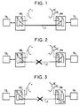
- FIGS. 1 to 8 schematically represent a data transmission system comprising, for the transmission of data between two data terminals, respectively TA and TB, each associated with a modem, respectively MA and MB, a dedicated link LS on which transmission is carried out in normal times, and an LRC link by the switched telephone network RC, on which the transmission is deferred in the event of degradation or break in the transmission on the dedicated link LS.
- FIGS. 1 to 8 also show, for each of the modems MA and MB, its data processing device, respectively 1A and 1B, and a routing and interface circuit with the links LS and LRC, respectively 2A and 2B, ensuring the separation of the transmission and reception directions for each of the links, and, according to the different stages of the method according to the invention, the connection of the transmission and reception accesses of the data processing device to the transmission and reception accesses thus dissociated from the LS link and / or the LRC link.
- the MA and MB modems require, for the description of the process according to the invention, to be arbitrarily differentiated.
- the call mode modem constituted for example by the MA modem
- the call mode modem is assigned the initiative to divert traffic from the dedicated link LS to the LRC backup link, in particular the call from the other modem, MB, says modem in mode dial-up telephone.
- a degradation or interruption of the transmission occurring on the LS link is symbolized in FIG. 2.
- the modems then observe, according to a conventional method, this malfunction and, in order to determine whether it is a degradation or of an interruption (which will be used as will be seen later to implement the return procedure according to the invention).
- the modem in call mode detects, as illustrated in FIG. 3, by means of an energy detector 3A, a possible presence of energy on its reception access to the link LS , while stopping its transmission on this link, so as not to detect the presence of energy due to an echo signal. It concludes with a deterioration in the case of such a presence, or with an interruption in the contrary case.
- the modem in call mode, MA then tries a connection with the modem in answer mode, MB, by the switched telephone network RC.
- a conventional phase of establishing communication by the switched telephone network RC then takes place.
- This phase includes dialing by the modem in MA call mode, during which the signals transmitted and received by the data processing device of this modem are, as illustrated in FIG. 4, routed to the LRC link, the number transmitted being that of the modem in MB response mode.
- the latter detects a call from the switched RC telephone network and, having, like the modem in call mode, observed a malfunction of the LS link (but without having to determine whether it was a degradation of the quality of the transmission or of an interruption of the transmission) connects, on this detection, the transmission and reception accesses of its data processing device to its transmission and reception accesses to the link LRC.
- the transmission can then be carried out on the LRC link, as illustrated in FIG. 5, where the LRC link is symbolized by a bold line, this transmission starting, for each of the modems, by a procedure for establishing a communication with the other modem.
- One of the modems known as the initiator modem for the LS link continuity check procedure, advantageously the modem in response mode, then transmits a data signal simultaneously on the LRC link and on the LS link, and the other modem , in this case the modem in call mode, detects a possible presence of energy on its reception access to the link LS, by means of the energy detector 3A, as illustrated in FIG. 5.
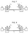
- the modem in MA call mode known as the initiator modem for the transmission quality check procedure on the LS link, attempts to transmit a data signal on this link, i.e. goes to the transmission position a data signal via this link and initiates a communication establishment procedure on the LS link, without releasing the LRC link, which is symbolized in FIG. 7 by a bold line for the two links and by the fact that the transmission and reception accesses of the modem data processing device in call mode are now connected to the transmission and reception accesses of this modem to the LS link.
- the modem in response mode attempts a transmission on the LS link, without however releasing the LRC backup link, which is also symbolized in FIG. 8 by a bold line. for these two links and by the fact that the transmission and reception accesses of the data processing devices of the two modems are now respectively connected to their transmission and reception accesses to the dedicated link.
- each of these modems then releases the LRC link, and the situation then returns to the initial situation shown diagrammatically in FIG. 1.
- the modems return, as illustrated in FIG. 5, to the position of data transmission by the LRC back-up link on which the transmission then takes place, after implementation of the procedure for establishing communication on this link, the modem in response mode however continuing to transmit on the LS link so that the modem in call mode can detect a presence of energy on its reception access to the LS link, this detection of presence of energy being however only carried out at the expiration of a time delay of 30 minutes for example, after which the situation becomes again that shown diagrammatically in FIG. 7 in the case of the presence of energy, or remains that shown schematically in Figure 5 otherwise, the detection of a possible presence of energy, then performed, being immediately.
- FIG. 9 A device for implementing the method thus described is shown in FIG. 9. This device is identical for the modem in call mode and for the modem in answer mode.
- This figure shows the processing device for data 1, the interface and switching circuit 2, which breaks down into a switching circuit 2 ′ and into an interface circuit 2 ⁇ , as well as the energy detector 3.
- the transmission and reception accesses to the data processing device are referenced respectively EM and REC.
- each of the links LS and LRC comprises two wires, respectively, 4, 5, and 6, 7, not specialized in transmission or reception.
- the interface circuit 2 ⁇ then comprises, for each of the LS and LRC links, a protection circuit, respectively 8, 9, and a transformer provided with a first winding, respectively 10, 11, connected to the wires of the corresponding link and a second winding, respectively 12, 13 of which a first end is grounded and a second end of which is connected to the input of a duplexer circuit, respectively 14, 15, making it possible to dissociate the accesses in transmission and on reception at these links, referenced respectively EMLS and RECLS for the LS link, EMLRC and RECLRC for the LRC link.
- the routing circuit 2 ′ makes it possible to connect the accesses EM and REC respectively to the accesses EMLS and RECLS, and / or EMLRC and RECLRC, according to the method described above. It therefore includes a switch 16 connected at the input to the transmission access EM, at the output to the access EMLRC, and controlled by a logic control signal referenced A from a sequencer 17 whose operating sequence will be described later.
- the routing circuit 2 ′ also includes a switch 17 ′ connected on the one hand to the access EM, on the other hand to the access EMLS, and controlled by a logic signal referenced B coming from the sequencer 17.
- the routing circuit 2 ′ also includes a multiplexer 18 having two data inputs connected respectively to the RECLS and RECLRC ports, an output constituting the REC port, and a control input to which the control signal A is applied.
- a double switch 19 controlled by a logic signal referenced F coming from the sequencer 17 and having the function of establishing or releasing the connection by the switched telephone network, according to the process described above.
- the signal present on the LRC link between the switch 19 and the protection circuit 9 supplies a call detector 20 providing the sequencer 17 with a logic signal referenced E.
- the signal available on the RECLS access further supplies the energy detector 3 providing the sequencer 17 with a logic signal referenced C.
- the sequencer 17 also receives a logic signal D indicating whether the reception of data by the considered modem is satisfactory or not, and obtained, for example, as illustrated in FIG. 9, at the output of a gate 22 performing a "or "logic between two signals S1 and S2 delivered by a circuit 1 ′ for analyzing received signals (included in the data processing device 1) and indicating either a deterioration in the quality of the received signals, or else the absence of such degradation, and the other an impossibility of synchronization or resynchronization, or else an effective synchronization or resynchronization, in the case of a transmission procedure based on an exchange between the two data terminals, one of them having the initiative of exchanges on the link used and being here associated with the modem in call mode.
- a logic signal D indicating whether the reception of data by the considered modem is satisfactory or not, and obtained, for example, as illustrated in FIG. 9, at the output of a gate 22 performing a "or "logic between two signals S1 and S2 delivered by a circuit 1
- the degradation of the quality of the signals is detected with respect to predetermined reference signals expected in the event of non-degradation, which is generally represented by a constellation of points in the Fresnel plane in the case of a modem performing a combination. phase modulation and amplitude modulation.
- Such a device for analyzing received signals is well known to those skilled in the art, being also used to control the switching of the normal link to the backup link in the event of unsatisfactory reception of the transmission on the normal link; it will therefore not be described again here.
- the sequencer 17 also supplies the data processing device with a signal G for controlling the start of the procedure for establishing a communication with the other modem and, in the case of the modem in call mode only, a signal H of call control of the other modem to establish a connection via the switched telephone network.
- the dialing transmission by the modem in call mode is done for example from the data processing device 1 in the case of dialing in multi-frequency mode, this device having in memory the telephone number of the modem in mode reply.
- the embodiment of the sequencer 17, illustrated by way of example in FIG. 9, comprises a microcontroller 171 connected by address, data and control buses, generally referenced 172, to a random access memory 173 allowing in particular to temporarily store the state of signals A, B, C, D, E, F, G, H, and to a read-only memory 174 containing the operating sequence of sequencer 17, in the form of an instruction program of the microcontroller 171.
- This phase P1 includes a permanent test of the state of the signal D, this test controlling maintenance of this initial phase in the case of a level "0" of this signal.
- each of the modems then returns to the initial phase P1 of transmission on the dedicated link.
- the LS link is now replaced by two links, LSA for transmission in the modem direction in call mode to modem in response mode, and LSB for transmission in the modem direction in response mode to modem in call mode.
- Figure 11 is, except for this difference, identical to Figure 1.
- a degradation or a break occurring on the LS link is symbolized in FIG. 12. It will be noted that this interruption or this degradation can affect either the LSA link or the LSB link, or these two links simultaneously.
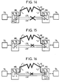
- the dialing phase by the modem in call mode is illustrated in FIG. 13.
- FIG. 14 differs from FIG. 5 in that it is now the modem in call mode which simultaneously transmits a data signal on the LRC link and on the LS link, that is to say in l occurrence on the LSA link, and the modem in response mode which detects a possible presence of energy on this link, the case of such a presence of energy on the LSA link being symbolized in FIG. 15.
- FIG. 16 a new step is introduced, illustrated in FIG. 16, where, upon detection of the continuity of the LSA link by the modem in response mode, the latter then transmits a data signal simultaneously on the LRC link and on the link LS, in this case on the LSB link, and the modem in call mode detects a possible presence of energy thereon, such presence of energy on the LSB link being symbolized in FIG. 17.
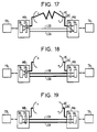
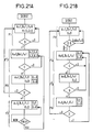
- FIG. 18 illustrates the next step where, on detection of the continuity of the LSB link, the modem in call mode attempts a transmission on the LS link, that is to say goes into position for transmission of a signal of data by this link and initiates a procedure for establishing communication on this link, without however releasing the LRC link.
- the modem in response mode having its reception access always connected to the LRC link then notices a disappearance of its signal on reception, which causes the passage to the next step, illustrated in FIG. 19, where the modem in response mode attempts in turn a transmission on the LS link.
- FIG. 20 A device for implementing the illustrated method in Figures 11 to 19 is shown in Figure 20.
- This device is identical for the modem in call mode and for the modem in answer mode.
- the elements which are identical to those presented in FIG. 9 have been identified using the same references.
- This device is identical to that of FIG. 9 except, in the interface circuit referenced here 200 ⁇ , interface elements with the dedicated link, for which two protection circuits 8 ′ and 8 ⁇ are now provided , each associated with one of the links, respectively LSA and LSB for example, as well as two transformers also each associated with one of the links and whose windings have been marked 10 ′ and 12 ′ for that associated with the LSA link and 10 ⁇ and 12 ⁇ for the one associated with the LSB link, and a duplexer circuit is no longer necessary.
- FIGS. 21A and 21B The operating sequence of the sequencer 17 is indicated in FIGS. 21A and 21B, for the modem in call mode and for the modem in answer mode respectively.
- FIGS. 10A and 10B the same references have been used as in FIGS. 10A and 10B to designate similar steps, which will therefore not be described again in detail.
- step P6 during which the modem in response mode in turn attempts a transmission on the link LS, without releasing the link LRC, is also similar to that already described in FIG. 10B.
- step P′7 is identical to step P′3 (as in FIG. 10A l step P7 was identical to step P3).
Landscapes
- Engineering & Computer Science (AREA)
- Computer Networks & Wireless Communication (AREA)
- Signal Processing (AREA)
- Communication Control (AREA)
- Detection And Prevention Of Errors In Transmission (AREA)
- Maintenance And Management Of Digital Transmission (AREA)
- Computer And Data Communications (AREA)
- Testing, Inspecting, Measuring Of Stereoscopic Televisions And Televisions (AREA)
Claims (12)
- Verfahren zur Rück-Umschaltung auf eine normale Verbindungsstrecke (LS) nach Benutzung einer Hilfsverbindungsstrecke (LR) in einem Datenübertragungssystem, das zwei solcher Strekken zwischen zwei Endgeräten aufweist, von denen die zweite im Falle eines gestörten Betriebs der ersten benutzt wird, wobei das Verfahren parallel zur Übertragung über die Hilfsstrecke eine vorherige Überprüfung der Kontinuität der normalen Strekke einschließt, dadurch gekennzeichnet, daß bei der vorherigen Überprüfung ein Datensignal durch eines der Endgeräte, das die Kontinuitätsüberprüfungsprozedur auslöst, gleichzeitig über die normale und über die Hilfsstrecke ausgesendet wird, und das andere Endgerät ein eventuelles Vorhandensein von Energie auf der normalen Strecke erfaßt, und zwar für jeden Übertragungsträger der normalen Strecke, falls diese unterschiedliche Träger für jede Übertragungsrichtung aufweist.
- Verfahren nach Anspruch 1, dadurch gekennzeichnet, daß auf die Ermittlung der Kontinuität der normalen Strecke durch Erfassung von Energie auf dieser Strecke in einer ersten Phase eine zweite Phase der Überprüfung der einwandfreien Qualität der Übertragung über diese Strecke folgt, ohne daß die Hilfsstrecke freigegeben würde, und zwar auf Initiative eines der Endgeräte, das die Prozedur zur Qualitätsüberprüfung auslöst.
- Verfahren nach Anspruch 2, dadurch gekennzeichnet, daß eine Rückkehr zur ersten Phase mit Übertragung über die nicht freigegebene Hilfsstrecke und gleichzeitiger Aussendung eines Datensignals durch das die Kontinuitätstestprozedur auslösende Endgerät über die normale Strecke und über die Hilfsstrecke und mit Erfassung eines eventuellen Vorhandenseins von Energie auf der normalen Strecke durch das andere Endgerät erst nach Ablauf einer Zeitdauer erfolgt, sofern die ordentliche Übertragungsqualität auf der normalen Strecke während der zweiten Phase nicht festgestellt wurde.
- Verfahren nach einem der Ansprüche 1 bis 3, dadurch gekennzeichnet, daß es parallel zur Erfassung des gestörten Betriebes der normalen Strecke eine Erkennung der Art des Übertragungsfehlers, nämlich die Unterbrechung oder nur die Verschlechterung der Qualität der Übertragung durchführt, die diese Strecke beeinträchtigt.
- Verfahren nach Anspruch 4, dadurch gekennzeichnet, daß bei einer Übertragungsstörung in Form einer Verschlechterung der Qualität der Übertragung die Erfassung eines eventuellen Vorhandenseins von Energie auf der normalen Strecke erst nach Ablauf einer Zeitdauer erfolgt.
- Verfahren nach einem der Ansprüche 2 bis 5, dadurch gekennzeichnet, daß das die Qualitätsüberprüfungsprozedur auslösende Endgerät nicht das die Kontinuitätsüberprüfungsprozedur auslösende Endgerät ist, wenn die normale Strecke keine nach Übertragungsrichtung getrennte Übertragungsträger besitzt.
- Verfahren nach einem der Ansprüche 2 bis 5, dadurch gekennzeichnet, daß die Kontinuitätsüberprüfung in zwei aufeinanderfolgenden Phasen erfolgt, wobei das die Qualitätsüberprüfungsprozedur auslösende Endgerät nicht das die zweite Phase der aufeinanderfolgenden Phasen auslösende Endgerät ist, wenn die normale Strecke getrennte Übertragungsträger für jede Übertragungsrichtung besitzt.
- Verfahren nach einem der Ansprüche 6 oder 7, dadurch gekennzeichnet, daß es nach Ermittlung der Kontinuität der normalen Strecke eine Zwischenphase zur Information des die Qualitätsüberprüfungsprozedur nicht auslösenden Endgerätes über den Übergang von der ersten zur zweiten Phase aufweist, die eine Aussendung über die normale Strecke durch das Qualitätsüberprüfungsprozedur auslösende Endgerät einschließt, während das die Qualitätsüberprüfungsprozedur nicht auslösende Endgerät noch über die Hilfsstrecke empfängt.
- Verfahren nach Anspruch 7, dadurch gekennzeichnet, daß, wenn die Hilfsstrecke eine über das Fernsprechvermittlungsnetz geführte Strecke ist und eines der Endgeräte, das sich im Rufmodus befindet, die Initiative zum Aufbau der Hilfsstrecke im Falle eines gestörten Betriebes der normalen Strecke ergreift, während das andere Endgerät sich im Antwortmodus befindet, das Endgerät, das die Kontinuitätsüberprüfungsprozedur auslöst, das im Antwortmodus befindliche Gerät ist, während das Endgerät, das die Qualitätsüberprüfungsprozedur auslöst, das im Rufmodus befindliche Gerät ist.
- Verfahren nach Anspruch 8, dadurch gekennzeichnet, daß, wenn die Hilfsstrecke eine über das Fernsprechvermittlungsnetz geführte Strecke ist und eines der Endgeräte, das sich im Rufmodus befindet, die Initiative zum Aufbau der Hilfsstrecke im Falle eines gestörten Betriebes der normalen Strecke ergreift, während das andere Endgerät sich im Antwortmodus befindet, das Endgerät, das die Qualitätsüberprüfungsprozedur auslöst, das im Rufmodus befindliche Endgerät ist, während das die Kontinuitätsüberprüfungsprozedur auslösende Endgerät in der ersten Phase das im Rufmodus befindliche Endgerät und in der zweiten Phase der aufeinanderfolgenden beiden Phasen das im Antwortmodus befindliche Endgerät ist.
- Datenübertragungssystem zur Durchführung des Verfahrens gemäß einem der Ansprüche 1 bis 10, das zwei Strecken (LS, LRC) zwischen zwei Endgeräten aufweist, wobei die zweite Strecke im Falle eines gestörten Betriebs der ersten Strecke benutzt wird, dadurch gekennzeichnet, daß das System in jedem Endgerät, das selber eine Einrichtung (1) zur Verarbeitung der von diesem Endgerät gesendeten und empfangenen Daten aufweist, enthält:- eine Weichenschaltung (2′), die die Verbindung der Sende- und Empfangsanschlüsse der Datenverarbeitungseinrichtung dieses Endgerätes mit seinen Sende- und Empfangsanschlüssen zur normalen Strecke und/oder zur Hilfsstrecke herstellt,- einen Energiedetektor (3), der mit dem empfangsseitigen Anschluß des Endgerätes mit der normalen Strecke verbunden ist; und- eine Folgesteuerung (17), die die vom Energiedetektor (3) kommenden Signale empfängt und als Antwort darauf die Weichenschaltung (2′) auf eine der beiden Strecken (LS, LRC) einstellt.
- System nach Anspruch 11 zur Durchführung des Verfahrens gemäß einem der Ansprüche 2 bis 10, dadurch gekennzeichnet, daß es weiter aufweist:- einen Detektor (1′) zum Feststellen des befriedigenden oder nicht befriedigenden Empfangs der von der Datenverarbeitungsvorrichtung (1) empfangenen Signale, wobei die Ausgangssignale dieses Detektors (1′) an die Weichenschaltung angelegt werden, und- einen Unterbrecher (19), der solange in der Schließstellung gehalten wird, wie die Hilfsstrecke nicht freigegeben werden soll, und der im entgegengesetzten Falle in der Öffnungsstellung gehalten wird, wobei der Unterbrecher von der Weichenschaltung betätigt wird.
Applications Claiming Priority (2)
| Application Number | Priority Date | Filing Date | Title |
|---|---|---|---|
| FR9005130 | 1990-04-23 | ||
| FR9005130A FR2661298B1 (fr) | 1990-04-23 | 1990-04-23 | Procede et dispositif de retour a une liaison normale apres utilisation d'une liaison de secours dans un systeme de transmission de donnees. |
Publications (2)
| Publication Number | Publication Date |
|---|---|
| EP0454036A1 EP0454036A1 (de) | 1991-10-30 |
| EP0454036B1 true EP0454036B1 (de) | 1995-02-01 |
Family
ID=9395980
Family Applications (1)
| Application Number | Title | Priority Date | Filing Date |
|---|---|---|---|
| EP91106457A Expired - Lifetime EP0454036B1 (de) | 1990-04-23 | 1991-04-22 | Verfahren und Anordnung für die Rückkehr zu einer normalen Verbindung nach Benutzung einer Hilfsverbindung in einem Datenübertragungssystem |
Country Status (9)
| Country | Link |
|---|---|
| US (1) | US5367562A (de) |
| EP (1) | EP0454036B1 (de) |
| JP (1) | JP2563854B2 (de) |
| AT (1) | ATE118139T1 (de) |
| AU (1) | AU648299B2 (de) |
| CA (1) | CA2040941C (de) |
| DE (1) | DE69107109T2 (de) |
| ES (1) | ES2067787T3 (de) |
| FR (1) | FR2661298B1 (de) |
Families Citing this family (15)
| Publication number | Priority date | Publication date | Assignee | Title |
|---|---|---|---|---|
| JP2763990B2 (ja) * | 1992-08-12 | 1998-06-11 | 富士通株式会社 | 2線式全二重モデム |
| FR2700650B1 (fr) * | 1993-01-15 | 1995-02-24 | Sat | Procédé de secours d'une liaison de réseau de télécommunications. |
| EP0761049B1 (de) * | 1994-05-27 | 2000-08-30 | BRITISH TELECOMMUNICATIONS public limited company | Datenübertragungssystem mit kanalumschaltungseinrichtung |
| SE503022C2 (sv) * | 1994-06-15 | 1996-03-11 | Ericsson Telefon Ab L M | Distribuerad förbindelsestyrning i telekommunikationsnät |
| JP3623997B2 (ja) * | 1994-12-28 | 2005-02-23 | 富士通株式会社 | デジタル交換機間中継方式及びデジタル交換機 |
| US6072857A (en) * | 1996-12-19 | 2000-06-06 | Bellsouth Intellectual Property Management Corporation | Methods and system for monitoring the operational status of a network component in an advanced intelligent network |
| US6018576A (en) * | 1996-12-31 | 2000-01-25 | Mci Communications Corporation | Method and apparatus for automated node-based normalization after network restoration |
| US6005920A (en) * | 1997-01-03 | 1999-12-21 | Ncr Corporation | Call center with fault resilient server-switch link |
| US5912963A (en) * | 1997-03-03 | 1999-06-15 | At&T Corp. | Method and apparatus for providing an alternate telecommunications network |
| US6215867B1 (en) * | 1997-06-20 | 2001-04-10 | At&T Corp. | Telecommunications network architecture with rapid restoration |
| EP1021757A1 (de) | 1997-07-25 | 2000-07-26 | Starvox, Inc. | Verfahren und vorrichtung für integriertes sprach-gateway |
| KR100297590B1 (ko) * | 1998-09-18 | 2001-08-07 | 서평원 | 교환기에서 스위치 네트워크의 경로 시험 방법 |
| EP2195975B1 (de) * | 2007-09-24 | 2012-04-25 | Ceragon Networks LTD. | Fehlerlose und störungslose kommunikation mit variabler datenrate |
| WO2009040801A2 (en) * | 2007-09-24 | 2009-04-02 | Ceragon Networks Ltd. | Protected variable data rate communication systems |
| CA2700402A1 (en) * | 2007-09-24 | 2009-04-02 | Ceragon Networks Ltd. | Maintaining a constant delay in point-to-point transmission |
Family Cites Families (20)
| Publication number | Priority date | Publication date | Assignee | Title |
|---|---|---|---|---|
| JPS5596739A (en) * | 1979-01-19 | 1980-07-23 | Nec Corp | Automatic switching stand-by system |
| FR2473820A1 (fr) * | 1980-01-11 | 1981-07-17 | Telecommunications Sa | Procede et systeme d'initialisation de la securisation d'une ligne d'une artere de transmission numerique |
| JPS56119569A (en) * | 1980-02-25 | 1981-09-19 | Nec Corp | Communication line switching system |
| JPS56153859A (en) * | 1980-04-28 | 1981-11-28 | Nec Corp | Pcm line switching device |
| JPS5856536A (ja) * | 1981-09-30 | 1983-04-04 | Fujitsu Ltd | 現用−予備切替方法 |
| JPS5877336A (ja) * | 1981-11-04 | 1983-05-10 | Toshiba Corp | オンラインシステムにおける回線切換方式 |
| JPS59191944A (ja) * | 1983-04-15 | 1984-10-31 | Ohkura Electric Co Ltd | デ−タ伝送路の監視切替装置 |
| CA1247206A (en) * | 1983-11-11 | 1988-12-20 | Satoshi Ikeuchi | Protection switching system for carrier transmission line |
| JPS60119147A (ja) * | 1983-12-01 | 1985-06-26 | Fujitsu Ltd | モデム切替方式 |
| JPS60208134A (ja) * | 1984-04-02 | 1985-10-19 | Nec Corp | 無線通信方式 |
| JPS6199452A (ja) * | 1984-10-13 | 1986-05-17 | Fujitsu Ltd | 受付台着信制御方式 |
| JPS61276438A (ja) * | 1985-05-31 | 1986-12-06 | Nec Corp | 回線品質測定方式 |
| US4887290A (en) * | 1987-08-05 | 1989-12-12 | Norbert W. Zawacki | Cellular alarm backup system |
| CA1321001C (en) * | 1988-02-04 | 1993-08-03 | Nec Corporation | Transmission line switching system |
| DE3881681D1 (de) * | 1988-03-15 | 1993-07-15 | Ibm | Mit einem fernsprechwaehlnetz verbindbares datenuebertragungssystem. |
| JPH0271637A (ja) * | 1988-09-07 | 1990-03-12 | Fujitsu Ltd | バックアップ方式 |
| US4862492A (en) * | 1988-10-26 | 1989-08-29 | Dialogic Corporation | Measurement of transmission quality of a telephone channel |
| GB8913735D0 (en) * | 1989-06-15 | 1989-08-02 | Grovag Grossventiltech | Isolators |
| JP2732674B2 (ja) * | 1989-07-10 | 1998-03-30 | 株式会社東芝 | データ伝送装置 |
| US4969178A (en) * | 1989-10-26 | 1990-11-06 | Telecommunication Laboratories, Directorate General of Telecommunications , Ministry of Communications | Multipurpose subscriber local line monitoring device |
-
1990
- 1990-04-23 FR FR9005130A patent/FR2661298B1/fr not_active Expired - Lifetime
-
1991
- 1991-04-19 AU AU75170/91A patent/AU648299B2/en not_active Ceased
- 1991-04-22 CA CA002040941A patent/CA2040941C/fr not_active Expired - Fee Related
- 1991-04-22 ES ES91106457T patent/ES2067787T3/es not_active Expired - Lifetime
- 1991-04-22 DE DE69107109T patent/DE69107109T2/de not_active Expired - Lifetime
- 1991-04-22 AT AT91106457T patent/ATE118139T1/de not_active IP Right Cessation
- 1991-04-22 EP EP91106457A patent/EP0454036B1/de not_active Expired - Lifetime
- 1991-04-23 JP JP3092258A patent/JP2563854B2/ja not_active Expired - Lifetime
-
1994
- 1994-03-01 US US08/203,766 patent/US5367562A/en not_active Expired - Lifetime
Also Published As
| Publication number | Publication date |
|---|---|
| JP2563854B2 (ja) | 1996-12-18 |
| ES2067787T3 (es) | 1995-04-01 |
| DE69107109T2 (de) | 1995-05-24 |
| EP0454036A1 (de) | 1991-10-30 |
| JPH04229739A (ja) | 1992-08-19 |
| FR2661298A1 (fr) | 1991-10-25 |
| DE69107109D1 (de) | 1995-03-16 |
| ATE118139T1 (de) | 1995-02-15 |
| FR2661298B1 (fr) | 1992-06-12 |
| CA2040941C (fr) | 1995-03-14 |
| US5367562A (en) | 1994-11-22 |
| AU7517091A (en) | 1991-10-24 |
| AU648299B2 (en) | 1994-04-21 |
Similar Documents
| Publication | Publication Date | Title |
|---|---|---|
| EP0454036B1 (de) | Verfahren und Anordnung für die Rückkehr zu einer normalen Verbindung nach Benutzung einer Hilfsverbindung in einem Datenübertragungssystem | |
| EP0032327B1 (de) | Verfahren und Anlage zur Sicherung eines digitalen Übertragungskabels | |
| CA1219980A (fr) | Dispositif de secours d'un terminal d'abonne dans un concentrateur numerique | |
| EP0032328B1 (de) | Verfahren und Anlage zur Einleitung der Sicherung einer Leitung eines digitalen Übertragungskabels | |
| EP0374670A1 (de) | Selbstheilende Vorrichtung einer Schleifenverbindung | |
| CH669057A5 (fr) | Installation de surveillance et d'alarme. | |
| FR2628549A1 (fr) | Systeme de commande de charges et procede pour deconnecter des bus secondaires d'un bus principal | |
| FR2477738A1 (fr) | Appareil de commande et de controle destine a etre utilise entre un poste central de calculateur et des postes terminaux | |
| FR2547686A1 (fr) | Circuit de test a bouclage de systeme de commutation | |
| EP0411529B1 (de) | Synchroner digitaler Sender | |
| FR2552246A1 (de) | ||
| FR2682190A1 (fr) | Procede de detection selective d'un defaut resistant dans un reseau de distribution d'energie electrique et dispositif pour sa mise en óoeuvre. | |
| EP0025767A1 (de) | Verfahren und Vorrichtung zum automatischen Prüfen eines digitalen Datenübertragungssystems | |
| EP0288353B1 (de) | Verfahren zur Umschaltung von asynchronen digitalen Signalen und Einrichtung zur Durchführung dieses Verfahrens | |
| EP0253039B1 (de) | Verfahren und Einrichtung zum Echoschutz in einem Modem | |
| FR2570563A1 (fr) | Un reseau local pour transmission de donnees numeriques sur cable telephonique et dispositif permettant la realisation de ce reseau | |
| EP0261003B1 (de) | Einrichtung zur schrittweisen Fernortung von Zwischenverstärkerpaaren in einer digitalen Leitung | |
| FR2695780A1 (fr) | Procédé de détection d'un court-circuit entre les lignes d'un bus transmettant des données numériques sous forme de signaux différentiels de tension. | |
| EP0350361A1 (de) | Vorrichtung für die Bewertung des Digitalvideosignaltoleranzbereichs | |
| FR2500246A1 (fr) | Dispositif de selection d'appareil terminal raccordable au reseau commute | |
| EP0936820B1 (de) | Verfahren und Vorrichtung zur Detektion von Teilnehmeranschluss-Anrufsignalen (CAS) auf einer Fernsprechleitung | |
| FR2700650A1 (fr) | Procédé de secours d'une liaison de réseau de télécommunications. | |
| EP0395483A1 (de) | Doppelringkommunikationssystem | |
| EP1021016A1 (de) | Gerät zur Unterscheidung von Fehlern auf einer digitalen Mietleitung | |
| FR2631194A1 (fr) | Procede de telemaintenance et de supervision de liaisons point a point |
Legal Events
| Date | Code | Title | Description |
|---|---|---|---|
| PUAI | Public reference made under article 153(3) epc to a published international application that has entered the european phase |
Free format text: ORIGINAL CODE: 0009012 |
|
| AK | Designated contracting states |
Kind code of ref document: A1 Designated state(s): AT BE CH DE ES FR GB IT LI NL SE |
|
| 17P | Request for examination filed |
Effective date: 19920422 |
|
| 17Q | First examination report despatched |
Effective date: 19930916 |
|
| GRAA | (expected) grant |
Free format text: ORIGINAL CODE: 0009210 |
|
| AK | Designated contracting states |
Kind code of ref document: B1 Designated state(s): AT BE CH DE ES FR GB IT LI NL SE |
|
| REF | Corresponds to: |
Ref document number: 118139 Country of ref document: AT Date of ref document: 19950215 Kind code of ref document: T |
|
| REF | Corresponds to: |
Ref document number: 69107109 Country of ref document: DE Date of ref document: 19950316 |
|
| REG | Reference to a national code |
Ref country code: ES Ref legal event code: FG2A Ref document number: 2067787 Country of ref document: ES Kind code of ref document: T3 |
|
| ITF | It: translation for a ep patent filed | ||
| GBT | Gb: translation of ep patent filed (gb section 77(6)(a)/1977) |
Effective date: 19950320 |
|
| PLBE | No opposition filed within time limit |
Free format text: ORIGINAL CODE: 0009261 |
|
| STAA | Information on the status of an ep patent application or granted ep patent |
Free format text: STATUS: NO OPPOSITION FILED WITHIN TIME LIMIT |
|
| 26N | No opposition filed | ||
| PGFP | Annual fee paid to national office [announced via postgrant information from national office to epo] |
Ref country code: AT Payment date: 19990324 Year of fee payment: 9 |
|
| PGFP | Annual fee paid to national office [announced via postgrant information from national office to epo] |
Ref country code: CH Payment date: 19990326 Year of fee payment: 9 |
|
| PGFP | Annual fee paid to national office [announced via postgrant information from national office to epo] |
Ref country code: NL Payment date: 19990329 Year of fee payment: 9 |
|
| PGFP | Annual fee paid to national office [announced via postgrant information from national office to epo] |
Ref country code: BE Payment date: 19990414 Year of fee payment: 9 |
|
| PG25 | Lapsed in a contracting state [announced via postgrant information from national office to epo] |
Ref country code: AT Free format text: LAPSE BECAUSE OF NON-PAYMENT OF DUE FEES Effective date: 20000422 |
|
| PG25 | Lapsed in a contracting state [announced via postgrant information from national office to epo] |
Ref country code: LI Free format text: LAPSE BECAUSE OF NON-PAYMENT OF DUE FEES Effective date: 20000430 Ref country code: CH Free format text: LAPSE BECAUSE OF NON-PAYMENT OF DUE FEES Effective date: 20000430 Ref country code: BE Free format text: LAPSE BECAUSE OF NON-PAYMENT OF DUE FEES Effective date: 20000430 |
|
| BERE | Be: lapsed |
Owner name: ALCATEL CIT Effective date: 20000430 |
|
| PG25 | Lapsed in a contracting state [announced via postgrant information from national office to epo] |
Ref country code: NL Free format text: LAPSE BECAUSE OF NON-PAYMENT OF DUE FEES Effective date: 20001101 |
|
| REG | Reference to a national code |
Ref country code: CH Ref legal event code: PL |
|
| NLV4 | Nl: lapsed or anulled due to non-payment of the annual fee |
Effective date: 20001101 |
|
| PGFP | Annual fee paid to national office [announced via postgrant information from national office to epo] |
Ref country code: SE Payment date: 20010402 Year of fee payment: 11 |
|
| REG | Reference to a national code |
Ref country code: GB Ref legal event code: IF02 |
|
| PG25 | Lapsed in a contracting state [announced via postgrant information from national office to epo] |
Ref country code: SE Free format text: LAPSE BECAUSE OF NON-PAYMENT OF DUE FEES Effective date: 20020423 |
|
| EUG | Se: european patent has lapsed |
Ref document number: 91106457.4 |
|
| PGFP | Annual fee paid to national office [announced via postgrant information from national office to epo] |
Ref country code: GB Payment date: 20100331 Year of fee payment: 20 |
|
| PGFP | Annual fee paid to national office [announced via postgrant information from national office to epo] |
Ref country code: FR Payment date: 20100506 Year of fee payment: 20 Ref country code: ES Payment date: 20100426 Year of fee payment: 20 |
|
| PGFP | Annual fee paid to national office [announced via postgrant information from national office to epo] |
Ref country code: IT Payment date: 20100426 Year of fee payment: 20 Ref country code: DE Payment date: 20100423 Year of fee payment: 20 |
|
| REG | Reference to a national code |
Ref country code: DE Ref legal event code: R071 Ref document number: 69107109 Country of ref document: DE |
|
| REG | Reference to a national code |
Ref country code: GB Ref legal event code: PE20 Expiry date: 20110421 |
|
| PG25 | Lapsed in a contracting state [announced via postgrant information from national office to epo] |
Ref country code: GB Free format text: LAPSE BECAUSE OF EXPIRATION OF PROTECTION Effective date: 20110421 |
|
| PG25 | Lapsed in a contracting state [announced via postgrant information from national office to epo] |
Ref country code: DE Free format text: LAPSE BECAUSE OF EXPIRATION OF PROTECTION Effective date: 20110422 |
|
| REG | Reference to a national code |
Ref country code: ES Ref legal event code: FD2A Effective date: 20130725 |
|
| PG25 | Lapsed in a contracting state [announced via postgrant information from national office to epo] |
Ref country code: ES Free format text: LAPSE BECAUSE OF EXPIRATION OF PROTECTION Effective date: 20110423 |